
Paper Substrate Classification based on 3D Surface Micro-geometry
Hossein Malekmohamadi
1
,Khemraj Emrith
2
, Stephen Pollard
1
, Guy Adams
1
, Melvyn Smith
2
and Steve Simske
1
1
Printing and Content Delivery Lab, Hewlett Packard Laboratories, Bristol, U.K.
2
Machine Vision Laboratory, University of the West England, Bristol, U.K.
Keywords:
Photometric Stereo, Shape index, Co-occurrence Matrices, Paper Classification.
Abstract:
This paper presents an approach to derive a novel 3D signature based on the micro-geometry of paper surfaces
so as to uniquely characterise and classify different paper substrates. This procedure is extremely important
to confront different conducts of tampering valuable documents. We use a 4-light source photometric stereo
(PS) method to recover dense 3D geometry of paper surfaces captured using an ultra-high resolution sensing
device. We derived a unique signature for each paper type based on the shape index (SI) map generated from
the surface normals of the 3D data. We show that the proposed signature can robustly and accurately classify
paper substrates with different physical properties and different surface textures. Additionally, we present
results demonstrating that our classification model using the 3D signature performs significantly better as
compared to the use of conventional 2D image based descriptors extracted from both printed and non-printed
paper surfaces. Accuracy of the proposed method is validated over a dataset comprising of 21 printed and 22
non-printed paper types and a measure of classification success of over 92%is achieved in both cases (92.5%
for printed surfaces and 96% for the non-printed ones).
1 INTRODUCTION
Counterfeit of valuable documents is growing at a
gigantic scale, mainly due to the rapid evolution of
modern printing technologies. Existing document se-
curity systems are unable to meet the requirements for
document security in terms of accuracy and robust-
ness prompting the need for more advanced, but cost-
effective methods to verify the authenticity and orig-
inality of print documents. The early stage to protect
valuable print documents is to recognise paper type.
Traditional methods (Chiang et al., 2009; Khanna
and Delp, 2010) to secure print documents use 2D
details of recorded digital images. However, recent
developments in fraud tampering make the job of
print security even tougher. Recent improvements in
extracting robust features for print inspection have
looked at acquiring high resolution 2D images of
printed materials for better feature extraction and rep-
resentation (Chiang et al., 2009). However with paper
surfaces being inherently isotropic with significantly
fine random details, the inspection or classification
systems based on 2D features has so far proved to
be considerably inaccurate. This can be mainly at-
tributed to the fact that direction of illumination has
a filtering effect which removes structural informa-
tion along the illumination direction (Chantler et al.,
2005). Additionally, studies using 2D features cap-
ture only variations in intensity of surfaces and fail to
capture the surface height variations, i.e. the 3D tex-
ture of surfaces being analysed (Cula and Dana, 2001;
McDaniel and Panchanathan, 2007).
For more precise paper substrate (printed and non-
printed) characterisation 3D surface representations
have been investigated. For example in (Buchanan
et al., 2005), Buchanan et al used a laser microscope
to image paper texture. While the system is able
to capture the 3D surface scattering, it is expensive
and cannot be widely applied. Clarkson et al (Clark-
son et al., 2009) used commodity scanners to capture
2D blank paper fingerprints and use the Photometric
Stereo (PS) method to extract 3D surface information.
Although relatively cheap, this method lacks in ro-
bustness and accuracy that arises from the inadequate
resolution of the scanners and the uncontrolled direc-
tional lights from the scanners.
To capture and model the surfaces of print materi-
als at micro-structure level, ultra-high resolution tech-
niques have been studied. In (Adams, 2010), a new
device to record 2D images of print in fine details is
448
Malekmohamadi H., Emrith K., Pollard S., Adams G., Smith M. and Simske S..
Paper Substrate Classification based on 3D Surface Micro-geometry.
DOI: 10.5220/0004690904480453
In Proceedings of the 9th International Conference on Computer Vision Theory and Applications (VISAPP-2014), pages 448-453
ISBN: 978-989-758-004-8
Copyright
c
2014 SCITEPRESS (Science and Technology Publications, Lda.)
introduced. Johnson et al (Johnson et al., 2011) em-
ployed elastomeric sensor to acquire images which
are later used by a PS algorithm to extract micro-
geometry of different surfaces. A 3-light source PS
system is used by Kuparinen et al (Kuparinen et al.,
2007) to extract paper surface topography. However,
none of these studies have provided a practical solu-
tion to develop a robust and secure system to identify
different paper types.
In this work we provide a model to classify paper
types using a novel signature that is based on the fine
3D structural information of paper materials. Using
a 4-light source PS method and microscopic photo-
metric images captured from a high resolution sens-
ing device we generate 3D surface texture at a mi-
crostructure level. We derive a novel 3D signature
based on the shape index (SI) map computed from the
surface normals. We show that different paper types
can be classified accurately, despite the presence of
print parasitics, meeting the requirements for forensic
paper inspection.
2 PHOTOMETRIC STEREO
To recover highly dense surface information, we
employ the PS technique which is based on high-
resolution image acquisition using a number of dif-
ferent light source directions and a single camera. PS
is used to estimate the dense normal map of a scene,
from which the gradient field is then computed. This
enables robust separation of the 2D (albedo) and 3D
(bump map) components of the scene at a signifi-
cantly high level of accuracy.
PS has been available for many decades (Wood-
ham, 1980) but only recently has affordable technol-
ogy become available for improving camera resolu-
tion and algorithm execution speed, allowing syn-
chronised light switching at the fast rates needed to
avoid inter-frame motion. We use 4 photometric im-
ages (4 source PS system) to recover the 3D sur-
face information from papers (blank or with glyph).
While fewer photometric images could be sufficient, a
4 source PS system allows better recovery in the pres-
ence of highlights and shadows (Barsky and Petrou,
2003). We assume a Lambertian reflectance model
together with intensity variation at each pixel to es-
timate local surface orientations. The integration of
these surface orientations results in a highly detailed
estimate of the surface geometry.
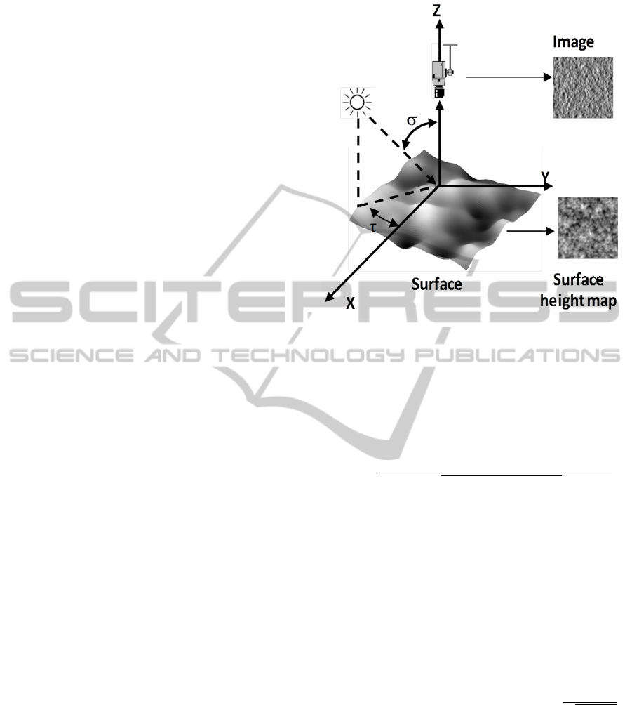
Figure 1 shows the set-up for the capture of pho-
tometric images. τ denotes tilt angle and represents
the angle that an illuminant vector projected onto the
surface plane makes with x-axis. The slant angle, σ,
Figure 1: Set-up for capturing images in PS algorithm.
represents the angle the illuminant vector makes with
the z-axis. The function to represent the photometric
images at individual illumination direction is as fol-
lows:
i(x, y) =
−p(x, y)cosτsinδ −q(x, y)sinτcosδ + cosδ
p
p(x, y)
2
+ q(x, y)
2
+ 1
(1)
It is important that the three photometric images
provide enough change in illumination gradient so
that the partial derivatives for the surface (p and q) can
be estimated. Based on the assumption that Lambert’s
law is preserved, we model that reflectance functions
for the 4 PS images as
i
d
(x, y) = ρ(l
d
n) ∀d ∈
{
1, 2, 3, 4
}
(2)
With known reflectance intensities i
d
and illumi-
nation directions l
d
(which are fixed in the camera co-
ordinate), the unit surface normal at a given position
(x, y) in the surface plane is given by n =
(p,q,−1)
T
√
p
2
+q
2
+1
with p and q being the partial surface derivatives.
3 EXPERIMENTAL SETUP
This section describes our photometric image capture
process and the generation of 3D surface datasets for
(non-) printed paper substrates.
PaperSubstrateClassificationbasedon3DSurfaceMicro-geometry
449
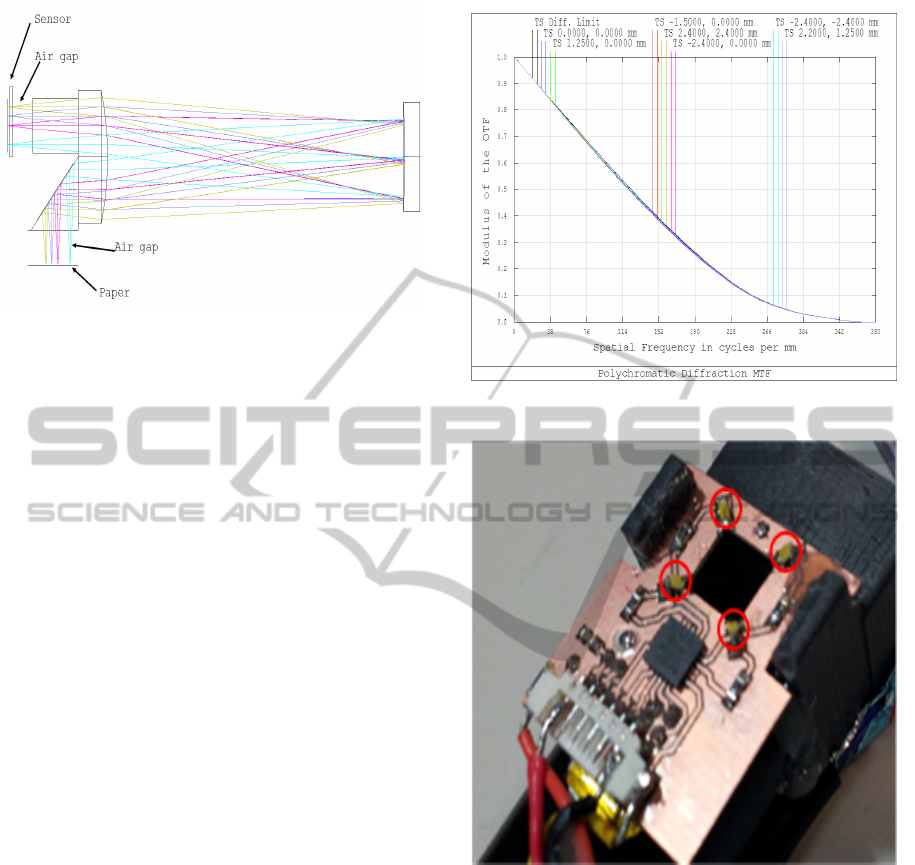
Figure 2: Imaging device.
3.1 Imaging Device
In this paper, we employ a similar device to (Adams,
2010; Simske and Adams, 2010) to capture the pho-
tometric images. Our device is capable of resolving
spatial features of less than 5 microns with 1:1 magni-
fication. Just as in the case of (Adams, 2010; Simske
and Adams, 2010) we also use a single Dyson relay
lens in series with a mirror and a low cost 3.2 m/pixel,
3 MP CMOS colour image sensor. However, we have
adapted our device for the current study by modify-
ing its design to accommodate a 4.5mm air-gap for
the paper and for the sensor as shown in Figure 2.
This gap enables light to be projected from multiple
sources and from a range slant angles. The sensor air
gap needs to be symmetrical due to the inherent re-
lay properties of the lens operation i.e. the input and
output paths to/from the mirror.
Theoretical resolution of the lens design over
a field of view (FOV) of 4.8mm is approximately
8800lpi (30% MTF (modulation transfer function)).
In practice with manufacturing and assembly toler-
ances this reduces to nearer 7000lpi. Figure 3 shows
that MTF at the diffraction limit (346 lines per mm
= 173 cycles/mm) and over the full FOV is approxi-
mately 0.4 which would result in satisfactory image
contrast. Due to the existing air gap, ambient illumi-
nation effects need proper consideration. An image is
captured with all LEDs off to record ambient illumi-
nation profile. Afterwards, this image is cancelled out
from captured images with LEDs on. The resultant
imaging device is shown in Figure 4.
3.2 3D Paper Surface Dataset
We generated an initial dataset with images captured
from a set of 22 different paper types. For every paper
type we captured photometric images from 12 random
locations. As a result the first dataset comprised of a
Figure 3: Simulated MTF over 5×5mm FOV.
Figure 4: An image of the device looking into the optics
(i.e. device is upside down). Image sensor and white LEDs
are assembled into a custom built, 3D printed frame.
total of 264 (i.e. 12×22) 3D surfaces.
To generate the dataset for printed surfaces, we
used a checkerboard pattern that was printed at 12
random locations of a set of 21 different paper types
(one ignored because of its thickness) leading to a set
of 252 3D surfaces. A laser printer was used in this
process.
Photometric images of size 1024×1024 pixels
were used to recover each 3D surface. Figure 5 shows
the rendered 3D surface of the same paper type from
the two different sets. Frankot & Chellapa’s method
(Frankot and Chellappa, 1988) was used to integrate
the partial derivatives of the surfaces. This is done
VISAPP2014-InternationalConferenceonComputerVisionTheoryandApplications
450
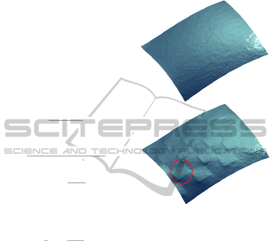
solely for visualisation purposes since we use only
the surface normals for feature extraction. Through
visual inspection we can identify the micro-geometry
of both the printed and non-printed regions.
4 3D SIGNATURE EXTRACTION
For the feature extraction stage, we use the partial
derivatives of the 3D surfaces (p,q) to extract surface
curvature information. We compute the first order
derivatives along the x-axis and y-axis for p and q: p
x
,
q
y
, p
y
. These derivatives are used to compute the sur-
face curvature. The Gaussian curvature, K, is given
by
K =
p
x
q
y
−p
y
2
(1 + p
2
+ q
2
)
2
(3)
Mean curvature is
H =
(1 + p
2
)q
y
+ (1 + q
2
)p
x
−2pqp
y
2(1 + p
2
+ q
2
)
3
2
(4)
The principle curvatures k
1,2
are
k
1,2
= H ±
p
H
2
−K (5)
The resultant principal curvatures are used to com-
pute a shape index (SI) map for each 3D surface. This
provides a characterisation of topography using a con-
tinuous angular representation (Koenderink and van
Doorn, 1992). Shape index is defined as
S =
2
π
arctan(
k
2
+ k
1
k
2
−k
1
) (6)
In Figure 6 we illustrate the shape index maps of
two surface patches extracted from same paper type
taken from dataset 1 and 2 respectively. The shape in-
dex maps presented appear to be able to capture sig-
nificant amount of 3D surface texture information in
both the printed and non-printed surface patches of
the paper type selected. More importantly, from the
shape index map of the printed paper (Figure 6 (bot-
tom) we can clearly see that the texture information of
the non-printed region is preserved together with the
texture information of the printed region being con-
siderably different.
The features used in the classification of the dif-
ferent paper types are obtained by extracting co-
occurrence information from the SI maps. These ma-
trices are computed using the local neighbourhood of
every SI map element (pixel) in the horizontal and
vertical directions (Haralick et al., 1973). Among the
Figure 5: Surface for a blank paper (top) and the same paper
with printed stimuli (bottom): for better visualisation, one
example of printed region is marked in red.
co-occurrence features, contrast and energy measures
are used in this paper. Contrast (δ) is computed from
the co-occurrence matrix (G) as follows:
δ =
∑
i, j
|i − j|
2
G(i, j). (7)
Energy (ε) is given by
ε =
∑
i, j
G(i, j)
2
. (8)
Finally, we extract entropy (ζ) for the SI map (S)
as
ζ = −
∑
i, j
S log
2
S (9)
Consequently, the features described in Table 1
are extracted for all 3D surfaces from both datasets
and are then fed to a classifier.
PaperSubstrateClassificationbasedon3DSurfaceMicro-geometry
451
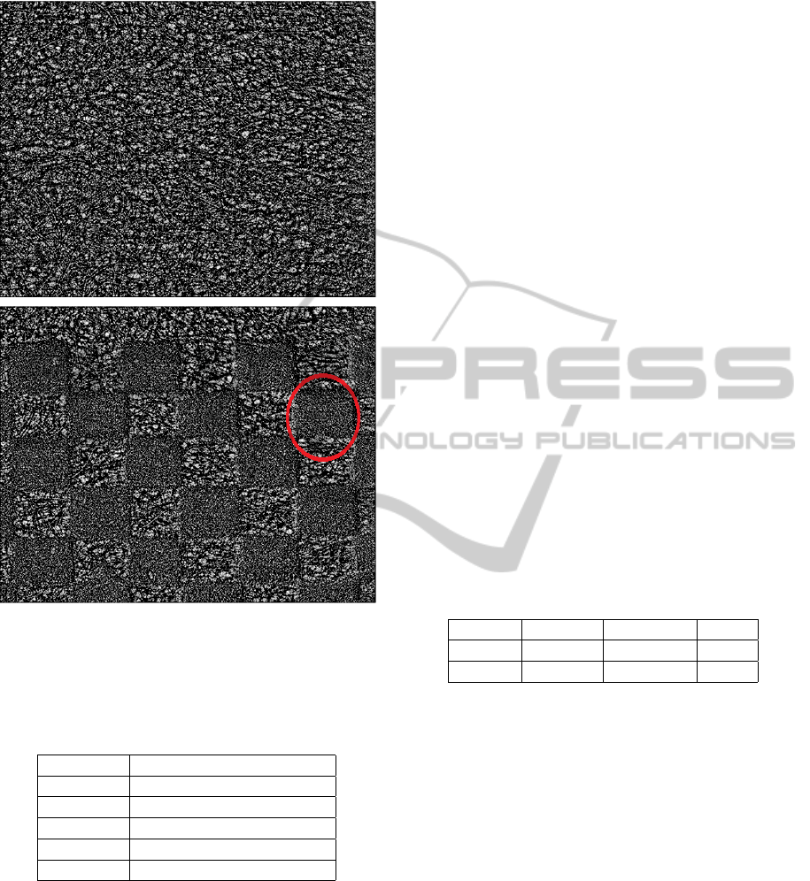
Figure 6: Surface for a blank paper (top) and the same paper
with printed stimuli (bottom): for better visualisation, the
corresponding SI region to the marked part of the surface
(See Figure 5) is circled in red.
Table 1: Set of parameters extracted for he SI map for non-
printed and printed datasets.
Parameter Description
δ
H
Horizontal Contrast for SI
δ
V
Vertical Contrast for SI
ε
V
Horizontal Energy for SI
ε
V
Vertical Energy for SI
ζ Entropy for SI
5 RESULTS & DISCUSSIONS
A neural network is used to train, validate and test the
data set to predict paper types from both datasets. In
the first experiment, we train a classifier to categorise
the different paper substrates. We use 50% of the
overall number of samples from each dataset for train-
ing purposes. An additional 15% is used to validate
the neural network to avoid overfitting. The remain-
ing 35% is then used for testing purposes. The neu-
ral network training function is based on Levenberg-
Marquardt optimisation (Marquardt, 1963). The num-
ber of neurons in the hidden layer is 5. To show the
improvement in classification from using 2D descrip-
tors, we apply the neural network classifier to features
extracted from the albedo map of each paper type.
The same features as presented in Table 1 are used.
5.1 Blank Paper Classification
(Dataset 1)
The results of applying the neural network classifier
to dataset 1 are shown in Table 2. Learning stops at
epoch 20 when the Mean Squared Error (MSE) for
validation data is 5.32. Table 2 shows the results of
applying the classifier to the albedo maps. For this
scenario, learning stops at epoch 91 when MSE for
validation data is 6.73. In the 2D scenario, some paper
types are misclassified (test performance is 86.42%)
whereas using 3D dense information they are more
clearly differentiated (test performance is 95.96%).
The reason is that in 2D case, statistical and structural
properties of similar paper types have closer values
but in the 3D case, similar paper types have more dis-
tinctive statistical and structural properties.
Table 2: Classification results with 3D and 2D information
for dataset 1.
Feature Training Validation Test
3D 92.33 94.08 95.96
2D 91.91 92.87 86.42
5.2 Printed Paper Classification
(Dataset 2)
In the case of applying the classifier to dataset 2,
learning stops at epoch 7 when MSE for validation
data is 4.29. The results for this classifier are shown
in Table 3. Learning stops at epoch 37 when MSE for
validation data is 6.64. Just as in the case of the results
in Section 5.1, using 2D features extracted from the
albedo images result in some paper types being mis-
classified (test performance is 89.36%). When fea-
tures are extracted from the dense 3D information,
the paper types are more clearly differentiated (test
performance is 92.55%).
Lower accuracy in the 2D scenario (features ap-
plied to the albedo map) for the non-printed dataset is
due to the fact that the statistical and structural prop-
erties of similar paper types are much closer than in
the 3D case. The difference between the 2D and 3D
VISAPP2014-InternationalConferenceonComputerVisionTheoryandApplications
452

results for printed papers is more muted. This is pos-
sibly because while much of the 3D structure of the
substrate is obliterated by the laser toner its interac-
tion with the substrate itself (which is evident equally
in 2D and 3D) still provides a useful key for classifi-
cation.
Table 3: Classification results with 3D and 2D information
for dataset 2.
Feature Training Validation Test
3D 91.72 95.4 92.55
2D 92.14 92.75 89.36
6 CONCLUSIONS
The 3D surface texture presented in this paper shows
promising attributes for a measure to be used for ac-
curate and robust classification of paper materials.
We presented an ultra-high resolution image sensing
device adapted to capture photometric images at a
micro-scale level. Using a 4-light source PS approach
we have demonstrated that we can recover 3D micro-
geometry for different types of paper substrates. Con-
sequently, we show that features extracted from the
recovered 3D micro-geometry can be used to charac-
terise and classify different categories of paper types
at significantly high-level of accuracy and easily out-
performs classification based on features extract from
2D surface information. Additionally the steps in-
volved in deriving the 3D signature have low com-
putational complexity and more importantly is very
cost-effective. We believe that a system based on the
model presented in this paper can have wide use in
several industries where document forgery is a con-
siderable threat.
REFERENCES
Adams, G. (2010). Hand held dyson relay lens for anti-
counterfeiting. In Imaging Systems and Techniques
(IST), 2010 IEEE International Conference on, pages
273–278. IEEE.
Barsky, S. and Petrou, M. (2003). The 4-source photomet-
ric stereo technique for three-dimensional surfaces in
the presence of highlights and shadows. Pattern Anal-
ysis and Machine Intelligence, IEEE Transactions on,
25(10):1239–1252.
Buchanan, J. D. R., Cowburn, R. P., Jausovec, A.-V., Pe-
tit, D., Seem, P., Xiong, G., Atkinson, D., Fenton, K.,
Allwood, D. A., and Bryan, M. T. (2005). Forgery:
‘fingerprinting’ documents and packaging. Nature,
436(7050):475.
Chantler, M., Petrou, M., Penirsche, A., Schmidt, M., and
MGunnigle, G. (2005). Classifying surface texture
while simultaneously estimating illumination direc-
tion. International Journal of Computer Vision, 62(1-
2):83–96.
Chiang, P.-J., Khanna, N., Mikkilineni, A., Segovia, M.
V. O., Suh, S., Allebach, J., Chiu, G., and Delp, E.
(2009). Printer and scanner forensics. Signal Process-
ing Magazine, IEEE, 26(2):72–83.
Clarkson, W., Weyrich, T., Finkelstein, A., Heninger, N.,
Halderman, J. A., and Felten, E. W. (2009). Finger-
printing blank paper using commodity scanners. In
Security and Privacy, 2009 30th IEEE Symposium on,
pages 301–314. IEEE.
Cula, O. G. and Dana, K. J. (2001). Recognition methods
for 3d textured surfaces. In Proceedings of SPIE con-
ference on human vision and electronic imaging VI,
volume 4299, pages 209–220.
Frankot, R. T. and Chellappa, R. (1988). A method for
enforcing integrability in shape from shading algo-
rithms. Pattern Analysis and Machine Intelligence,
IEEE Transactions on, 10(4):439–451.
Haralick, R. M., Shanmugam, K., and Dinstein, I. H.
(1973). Textural features for image classification. Sys-
tems, Man and Cybernetics, IEEE Transactions on,
(6):610–621.
Johnson, M. K., Cole, F., Raj, A., Adelson, E. H., et al.
(2011). Microgeometry capture using an elastomeric
sensor. ACM Trans. Graph., 30(4):46.
Khanna, N. and Delp, E. J. (2010). Intrinsic signatures for
scanned documents forensics: effect of font shape and
size. In Circuits and Systems (ISCAS), Proceedings of
2010 IEEE International Symposium on, pages 3060–
3063. IEEE.
Koenderink, J. J. and van Doorn, A. J. (1992). Surface shape
and curvature scales. Image and vision computing,
10(8):557–564.
Kuparinen, T., Kyrki, V., Mielik
¨
ainen, J., and Toivanen, P. J.
(2007). Paper surface topography using three-light
photometric stereo. In MVA, pages 45–48. Citeseer.
Marquardt, D. W. (1963). An algorithm for least-squares es-
timation of nonlinear parameters. Journal of the Soci-
ety for Industrial & Applied Mathematics, 11(2):431–
441.
McDaniel, T. and Panchanathan, S. (2007). Perceptual sur-
face roughness classification of 3d textures using sup-
port vector machines. In Haptic, Audio and Visual
Environments and Games, 2007. HAVE 2007. IEEE
International Workshop on, pages 154–159. IEEE.
Simske, S. J. and Adams, G. (2010). High-resolution glyph-
inspection based security system. In Acoustics Speech
and Signal Processing (ICASSP), 2010 IEEE Interna-
tional Conference on, pages 1794–1797. IEEE.
Woodham, R. J. (1980). Photometric method for determin-
ing surface orientation from multiple images. Optical
engineering, 19(1):191139–191139.
PaperSubstrateClassificationbasedon3DSurfaceMicro-geometry
453
