
Towards a Heuristic based Real Time Hybrid Rendering
A Strategy to Improve Real Time Rendering Quality using Heuristics and Ray
Tracing
Paulo Andrade, Thales Sabino and Esteban Clua
Instituto de Computac¸˜ao, Universidade Federal Fluminense, Niter´oi, Brazil
Keywords:
CUDA, Deferred Shading, Global Illumination, Hybrid Rendering, OptiX
TM
, Rasterization, Ray Tracing,
Real Time Rendering.
Abstract:
Hybrid rendering combines the speed of raster-based rendering with the photorealism of ray trace rendering
in order to achieve both speed and visual quality for interactive applications. Since ray tracing images is a
demanding task, a hybrid renderer must use ray tracing carefully in order to maintain an acceptable frame rate.
Fixed solutions, where only shadows or reflexive objects are ray traced not only cannot guarantee real time,
but can represent a waste of processing, if the final result minimally differs from a raster only result. In our
work, we present a method to improve hybrid rendering by analysing the scene in real time and decide what
should be ray traced, in order to provide the best visual experience within acceptable frame rates.
1 INTRODUCTION
Visual realism is one of the key resources to im-
merse gamers and virtual reality (VR) users in ar-
tificial environments. The more “real” are the im-
ages, the more immersive is the user experience. Un-
fortunately, photorealism is the realm of static im-
ages and movies, where a single image (or frame)
could take hours to render using global illumina-
tion techniques. Photorealism in games (Kaplanyan,
2010a; Kaplanyan, 2010b) and virtual reality applica-
tions (Livatino, 2007) is still far away from the qual-
ity achieved by current visual effect intensive movies.
The problem is not only the processing power limita-
tions of current machines. Current real-time renderers
do not deal well with reflections, refractions, diffuse
scattering, ambient occlusion, caustics and complex
shadows (Akenine-M¨oller et al., 2008). Even worse
if these effects are generated in constantly changing
environments.
Even with limitations, to achieve photorealism us-
ing raster based real time rendering, programmers
have been developing and implementing many clever
tricks to simulate global illumination effects in real-
time. Techniques like cube maps (Knecht et al., 2013)
for reflections and shadow maps (Rosen, 2012) to
simulate areas where the light is blocked by elements
are some of the many strategies to simulate real world
optical effects in real-time. These tricks cannot be
applied to all situations, forcing level and environ-
ment designers to change their designs in order to deal
with this limitations. This burden limit the vision of
artists and slows virtual environments design for both
games and VR applications. The opposite side of the
coin is the global illumination used by off-line render-
ers. Global illumination (Suffern, 2007) is a general
name for a group of algorithms, in computer graph-
ics, that simulate the way light propagates in the envi-
ronment. Global illumination techniques are very de-
manding but produce better results than raster-based
techniques. One of the most studied global illumina-
tion technique is ray tracing. In ray tracing, the trac-
ing of a path of light through pixels in an image plane,
in the direction of a virtual scene, produces an image
the represents the scene. When the light ray hit an
object, the characteristics of the surface of the object
determine if the light ray should reflect, refract, scat-
ter, disperse or stop. To produce shadows, when a
ray hit a surface, shadow rays traced from the surface,
moves in the direction of every light in the scene. If
the shadow ray collides with a surface before arriv-
ing at the light source, the corresponding pixel in the
image is considered to be in a shadow area for that
particular light, if not, the colour of the pixel is in-
fluenced by the colour and intensity of the light. The
final colour of every pixel of the image is the result of
the surface and the influence of many rays traced in
the scene.
12
Andrade P., Sabino T. and Clua E..
Towards a Heuristic based Real Time Hybrid Rendering - A Strategy to Improve Real Time Rendering Quality using Heuristics and Ray Tracing.
DOI: 10.5220/0004691300120021
In Proceedings of the 9th International Conference on Computer Vision Theory and Applications (VISAPP-2014), pages 12-21
ISBN: 978-989-758-009-3
Copyright
c
2014 SCITEPRESS (Science and Technology Publications, Lda.)

Since current raster renderers are not capable of
rendering true photorealistic images and global illu-
mination techniques cannot render complex scenes in
real-time, one approach is combine raster and global
illumination rendering in one single solution for real
time rendering. In this case, global illumination is
used only when the technique can improve the quality
of the final image. This solution is still far from feasi-
ble since most global illumination techniques are, in
many orders of magnitude, more demanding in pro-
cessing power than raster-based techniques. In ad-
dition, considering the graphics processor evolution,
raster based rendering influence and are influenced
by the development of graphics processors special-
ized in the generation of raster-based images in real
time. These processors, also called Graphics Proces-
sors Units (GPUs), are dedicated to produce sophisti-
cated raster based images in real time.
With the development of GPUs that can also work
as massive parallel processors (Nickolls and Dally,
2010), GPU based hybrid rendering, that use both
raster and ray tracing techniques to create images, be-
came an interesting research topic. The basic ray trac-
ing algorithm is naturally parallelizable (Bigler et al.,
2006), making GPUs that also works as massive par-
allel processors a promising platform to produce in-
teractive, or even real time ray traced images. The
possibility of interactive ray tracer using a GPU only
approach was proven by NVidia, when they presented
their Design Garage Ray Racing Demo (Ludvigsen
and Elster, 2010). One of the most successful cases
of interactive ray tracing using GPUs is NVidia’s Op-
tiX (Parker et al., 2010) engine. OptiX is an interac-
tive ray tracing engine that is being used in profes-
sional applications like Adobe After Effects and Lu-
mion3D.
Hybrid rendering is a recent research topic (Her-
tel and Hormann, 2009; Lauterbach, 2009; Sabino
et al., 2012; Sabino et al., 2011). The main prob-
lem with hybrid rendering solutions is guaranteeing
a steady frame rate. With a raster only solution, the
designer can interactively test the environment and
change elements in order to increase the frame rate.
The environment designer can reduce the number of
polygons in the viewport by moving objects to other
places in the scene, using simplified versions of the
objects with fewer polygons, applying simpler ma-
terials and so on. In a hybrid raster and ray tracing
renderer, the number of polygons is just part of the
challenge. Since, in ray tracing, the way surfaces re-
act to light can also impact the overall performance,
demanding the use of more rays, the challenge to de-
velop environments that maintain an expected frame
rate is many times more complex than in a raster only
renderer.
In this paper, we try to reduce the burden of en-
vironment designers by presenting a heuristic to dy-
namically select objects and effects to be ray traced in
a hybrid raster and ray tracing renderer. The proposed
heuristic considers resource constraints and can be
used as a starting point to develop new ways to design
environments that can be visually rich, by using ray-
tracing effects, without affecting performance. Our
heuristic can also reduce the overall work of environ-
ment designers, by reducing the work involved in the
testing phase of the environments, since the hybrid
ray tracing can adapt, in real time, the final result.
This work improves the work presented in (An-
drade et al., 2012), by implementing more ray tracing
features in the hybrid renderer,allowing better render-
ing results.
2 RELATED WORK
Before the proposal of hybrid renderers, the first step
towards improving visual quality in real time appli-
cations was the development of GPU based real time
ray tracing (RTRT) renderers (Parker, 2009; Garcıa
et al., 2012; Bikker, 2013; Bikker and van Schijndel,
2013). However, experiments demonstrate that even
using current parallel architectures, RTRT renderers
cannot compete in speed and overall visual quality
with state of the art raster renderers. One method pro-
posed to increase frame rate in RTRT renderers is di-
vide the ray tracing workload between the CPU and
the GPU (Bikker, 2013; Chen and Liu, 2007), where
a GPU accelerated rasterization with Z-buffer is used
to determine the first ray-triangle hit of eye rays (pri-
mary rays). Secondary rays are generated using the
CPU in order to provide global illumination effects.
Approaches like that work, but still can not compete
in quality with state of the art raster renderers. A pow-
erful path tracer for real-time games that worth men-
tion is Brigade (Bikker and van Schijndel, 2013).
Another strategy employed by hybrid renderers is
use ray tracing strictly for specific light effects that
are slower or cannot be easily done in a raster only
renderer. (Hertel and Hormann, 2009) uses a kD-tree
accelerated ray tracer to determine shadow-ray inter-
sections, in order to improve the quality of highly de-
tailed shadows. (Lauterbach, 2009) also use ray trac-
ing in to improve the quality or hard and soft shadows
using a similar approach.
With the introduction of Multiple Render Targets
in both DirectX 9 and OpenGL 2.0, developers started
to use a shading strategy denominated deferred shad-
ing (Thibieroz and Engel, 2003) to enhance visual
TowardsaHeuristicbasedRealTimeHybridRendering-AStrategytoImproveRealTimeRenderingQualityusing
HeuristicsandRayTracing
13

quality of raster renderers, by implementing a post-
production rendering pass. With the possibility of
implementing a process of multiple render passes,
researchers started to use a pass to include specific
ray tracing light effects in the rendering pipeline.
(Wyman and Nichols, 2009) use a ray tracing pass to
create superior caustic effects while (Cabeleira, 2010)
and (Sabino et al., 2011) use ray tracing to include ac-
curate reflections and refractions. None of these ap-
proaches deals with the performance challenges re-
sulted by combining different render strategies and
are only feasible in specific scenarios.
Another research topic related to this work is se-
lective rendering (Cater et al., 2003; Chalmers et al.,
2007; Cater et al., 2002; Green and Bavelier, 2003).
Selective rendering consider psychophysical investi-
gations on how the human visual perception works,
in order to determine whether a detailed feature in an
image is visible to the eye. Based on these observa-
tions, it is possible to avoid unnecessary computations
involved in the creation of some features of the image.
Selective rendering is strongly influenced by the way
the viewer interact with the image or sequence of im-
ages.
Visual attention in real time applications (El-Nasr
and Yan, 2006; Sundstedt et al., 2005; Cater et al.,
2003) is also an influence in this work. The way
users interpret and react upon what they see in a real
time environment is highly affected by many factor
like speed of the virtual movement inside the environ-
ment, recent past experiences inside the virtual envi-
ronment, user attitude towards the exploration of the
environment, psychological experiences provided in-
side the virtual environment among other factors.
3 GPU BASED HYBRID
RENDERING
In order to evaluate our heuristics, a GPU based hy-
brid raster and ray tracing renderer was developed.
Our renderer, called PHRT, was developed in a way
that it allows the use of specific information of ev-
ery object inside the target scene and parametric in-
formation outside the scene to control the rendering
process, in order to offer a very flexible set of tools
to test heuristics. A heuristic can use specific infor-
mation contained in each object, specific information
contained in the materials of each object, general in-
formation of the scene, information generated during
the environment exploration and parametric informa-
tion defined outside the environment. PHRT is also
capable of following predefined virtual and automati-
cally collect information during the virtual trip inside
the environment. Information like frame rate and ob-
jects selected for ray tracing are stored for later anal-
ysis.
As most of today’s state of the art real time render-
ers, our renderer employs a technique called deferred
rendering (also known as deferred shading) (Pritchard
et al., 2004). The basic idea is to compute all the
geometry visibility tests before any light computa-
tion (shading) happens, using a raster based process.
By separating the geometry rendering from the light
processing and by using visibility tests, the shading
process in done only for specific polygons, avoid-
ing multiple light computations for the same pixel,
for elements outside the visible space, a problem that
must be treated in forward rendering approaches. The
visible geometry determination process is equivalent
to the primary ray hit phase of a ray tracer, where
eye rays projected from a virtual point of view are
launched in the direction of the scene, crossing a view
plane defined by a grid of pixels, that will later repre-
sent the final image. When a ray collide with the sur-
face of an object, the collision result in information
about the object, its surface and geometry. This in-
formation can be used to define the final the colour of
every pixel in the grid. Since the visibility test made
by the GPU in raster based renderers is very fast, this
process can easily substitute the first phase of a ray
tracer.
During the first raster render pass, where the visi-
bility tests are computed, other information like scene
Z-depth, surface normals and texture coordinates are
also computed. This set related information about
the scene are called G-Buffer data and are stored in
memory buffers denominated Multiple Render Tar-
gets (MRTs). The G-Buffer data is used in subsequent
render passes of a raster renderer and also in our hy-
brid renderer.
With the information corresponding to the pri-
mary ray intersection and the correspondinggeometry
of the scene, specific rays for shadows, direct and in-
direct light, refractions, reflections, caustics and other
effects are calculated and added to the already created
data in the MRTs, according to the way the final im-
age must be created.
The deferred rendering approach in hybrid render-
ing allows the selection of which visual effects the
ray tracing method will create and which effects are
the responsibility of other render strategies, allowing
flexibility in the implementation of PHRT.
PHRT is a highly improved version of the hybrid
real time renderer developed by (Sabino et al., 2012).
Sabino’s renderer employ Nvidia’s OptiX
TM
(Parker,
2009; Parker et al., 2010) to deal with the ray trace
stage of the renderer.
VISAPP2014-InternationalConferenceonComputerVisionTheoryandApplications
14
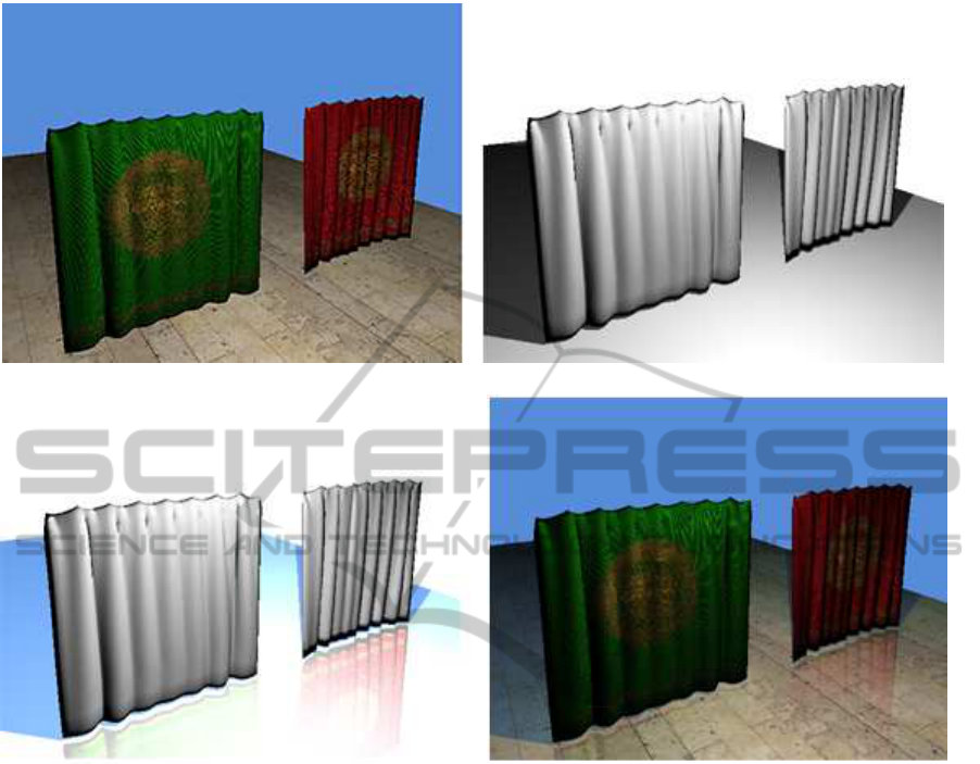
(a) Difuse colour (b) Shadows
(c) Reflections (d) Final composite
Figure 1: Four images of the render stages.
3.1 Deferred Rendering and Primary
Ray Resolution
During this stage, after all the data is stored in the
GPUs memory, a deferred shading pass is calculated
in order to fill the G-Buffer. The G-Buffer has now
the information needed for the visible geometry test
necessary for the other phases of PHRT.
3.2 Ray Tracing Shadow Calculation
With the information stored in the G-Buffer, OptiX
TM
is used to calculate shadow rays for every light source
of the scene. The ray tracing shadow phase can be
specifically ignored for some objects, according to the
heuristic, environment information and external pa-
rameters.
3.3 Ray Traced Reflections and
Refractions
Reflections and refractions also use information
stored in the G-Buffer. Similar to the shadow phase,
the heuristic, environment information and external
parameters are used to define which objects should
have reflections and/or refractions in the final com-
positing of the scene’s image.
3.4 Composition
The composition stage is the final stage of the
pipeline, where all the information produced by the
other steps are combined in order to produce the final
image for the frame. Figures 1(a) to 1(d) represent the
four stages of the hybrid renderer, where both shad-
ows and reflections are created using ray tracing.
TowardsaHeuristicbasedRealTimeHybridRendering-AStrategytoImproveRealTimeRenderingQualityusing
HeuristicsandRayTracing
15

4 A HEURISTIC FOR OBJECT
AND LIGHT EFFECTS
SELECTION
Since one of the main requisites of PHRT is a steady
frame rate, one of the main constraints for the ray trac-
ing phase is the time available after the raster phase.
Even to produce the simplest light effect, ray tracing
is a demanding task and can seriously drain process-
ing resources if not used with caution. One of the
reasons of its high cost is the recursive nature of the
ray tracing algorithm. In order to create global illu-
mination effects, light rays must bounce from surface
to surface, in order to create indirect illumination and
other light effects. The number of light rays bounces
and the sequential nature of the bounces can strongly
affect the render pipeline and the global performance.
A common way to control render time in offline ray
trace rendering is to establish a limit in both the num-
ber of ray bounces and the number of secondary rays
produced in every bounce. Depending on the surface
characteristics, a ray collision can produce more than
one new ray, greatly affecting the performance.
Depending on factors such as type of light effect,
characteristics of the surface, number of lights in the
scene and relative size of the visible portion of the el-
ement to be ray traced, the time spent in the ray trace
phase can surpass the time available for the phase.
So, the heuristic must choose wisely which elements
must be ray traced in a given time and with what con-
straints, in order to maintain the ray tracing phase in
its time constraints.
The heuristic must also consider the contribution
in the overall visual experience, in order to produce
the best possible image. This overall visual experi-
ence is not a static factor as the other components of
the problem. Depending on the motivation of the user
inside the virtual environment, some objects and light
effects can be more relevant than others can.
4.1 Object and Effect Selection
Considering only the objects that should be involved
in the ray tracing phase, we can define the heuristic
as: “for a given X objects, select the Y most relevant
objects that can be traced given a time limit T”, where
X is the objects that are relevant for the image gener-
ation in a given time and T is the available time for
the ray tracing phase. Both parameters X and T can
change its values for every frame generation.
The reason behind the idea of choosing a subset
of objects that best contribute to the visual experi-
ence came from the real world perception that when
images change constantly, as when we drive a car or
walk in the street, the mind ignores many visual ele-
ments. This is the reason we have orientation signs in
the streets. Signs call attention to inform about some-
thing relevant. In a first person shooter game or in a
driving simulator, the faster the experience is the less
is the perception of detail of the environment.
Considering the way the human vision works, it
is reasonable to assume that objects near the centre
of the field of view are more important than objects
far from it. The same can be said for objects near
the observer. Another observation is that according to
environment conditions (weather, indoor, under wa-
ter, for example), some objects cannot be visually im-
proved by ray tracing effects. Another situation that
can affect visual perception is the user’s motivation
in a given moment. If, for example, the user is look-
ing for a gold coin in the environment, the user will
be more susceptible to pay attention to golden ob-
jects. With these observations, the heuristic can be
expanded to: “for a given X objects, select the Y ob-
jects nearest from the centre of the field of view and
from the observer, that most contribute to the visual
experience, considering the ray trace effects to be ap-
plied, and that can be used in the ray tracing pass con-
sidering the time constraint T”.
4.2 The Heuristic
The proposed heuristic has five phases, an offline
phase, two fixed phases that happen before the ren-
dering and two phases that happen for every frame.
The first offline phase, called pre-production
phase, consist in identify and select the objects and
their relative effects that must be used in the ray trac-
ing pass, for a given environment. This information
is defined by the environment designer or automati-
cally generated by an algorithm that analyses every
object, it’s characteristics and relationship with other
elements in the scene. In both cases, every object
in the environment receives a fixed importance map
value that consist of the priority of this object for the
ray tracing phase. The importance map could consist
in only one value or a group of values, where each
value, in the group of values, represent a situation re-
lated to the user experience inside the environment.
This map of values can define, for example, that a
transparent object is very important during a daylight
experience inside the virtual environment and not im-
portant at all if the experience changes to a night ex-
ploration. In the tests tests done for this work, we only
use one fixed value, but PHRT can deal with many
fixed values for every object.
The first offline phase, called pre-production
phase, consist in identify and select the objects and
VISAPP2014-InternationalConferenceonComputerVisionTheoryandApplications
16

their relative effects that must be used in the ray trac-
ing pass, for a given environment. This information
is defined by the environment designer or automati-
cally generated by an algorithm that analyses every
object, its characteristics and relationship with other
elements in the scene. In both cases, every object
in the environment receives a fixed importance map
value that consist of the priority of this object for the
ray tracing phase. The importance map could consist
in only one value or a group of values, where each
value, in the group of values, represent a situation re-
lated to the user experience inside the environment.
This map of values can define, for example, that a
transparent object is very important during a daylight
experience inside the virtual environment and not im-
portant at all if the experience changes to a night ex-
ploration. In the tests tests done for this work, we only
use one fixed value, but PHRT can deal with many
fixed values for every object.
Still during the pre-productionphase, every object
receives an importance factor (K). The importance
factor is based on both the first and the second offline
phase and is considered the result of the second phase.
This importance factor defines how important is each
object in respect with the others. Also, every object
has an initial visibility cost (V), and the correspond-
ing estimated number of rays to be used to generate
each visual effect related to the object (Q). (Q) can be
a list of values for each object, with each value corre-
sponding to an estimated cost for every effect, or can
be the sum of costs involved to produce all the visual
effects. (V) and (Q) are also automatically created
during the second offline phase.
Visibility (V) is defined by the average area (A)
of the 2D projection of the object in the view plane
multiplied by the distance of the centre of the 2D pro-
jection to the distance of the view plane (P), divided
by the distance (D) of the object from the view plane
in the 3D space. The higher the object distance, the
less visible the object is. The visibility equation is
presented in equation (1). The total cost (C) for a
given object is presented in equation (2).
V =
A· P
D
(1)
C = V · Q (2)
The distance of the object center to the view plane
center (P) is normalized as a value between [0, 1],
where a value of 1 means that the center of the object
projection is in the same position of the view plane
center, and a value of 0 means that the object is out of
the field of view.
To select each object is also necessary to calculate
the relevance factor (R), where (R) is based on the
fact that the object was selected or not to be traced
in the previous frame (S) generation phase. (S) is a
binary variable, where 1 means that the object was
previously selected, and 0 means the it was not. The
importance of selecting previously selected objects is
also a fixed factor, present in the information about
environment and defined by the variable (I). Equa-
tion (3) is used to define the object relevance.
R = (S· I +V) · K (3)
For every frame, all the equations are calculated
for each object, in order to update the selection graph
with the current information of the environment.
Table 1 present all parameters discussed before
and inform if the parameter has their value constant
or variable during the render phase.
Table 1: Equation Parameters.
Param. Definition Const. Var.
K Object relevance
among the others
X
V Object visibility X
Q Estimated number of
secondary rays
X
C Processing cost X
A Projected area X
P Distance from the
view plane center
X
D Distance from the ob-
server
X
R Relevancy X
S Previously selected X
I Previously selection
relevance
X
The third phase happens during the render phase,
when the GPU receives the selection graph. Every
node in the graph represents an object to be traced
and every node point to the second node with cost (C)
smaller than the cost of the previous node, but larger
than the costs of the other nodes already in the graph.
Every node also points to N other nodes not selected
to render, where relevancy (R) is bigger than the rele-
vancy of the actual node. The pointers for other nodes
with higher relevancy are ordered by its relevancy.
When an object finishes rendering, the graph is
traversed to find other node where the cost (C) is
smaller than the time available for the ray tracing
phase. When the node with a suitable cost is found,
all the other nodes with higher cost are removed from
the graph and inserted in another graph that is being
built for the next frame generation.
TowardsaHeuristicbasedRealTimeHybridRendering-AStrategytoImproveRealTimeRenderingQualityusing
HeuristicsandRayTracing
17
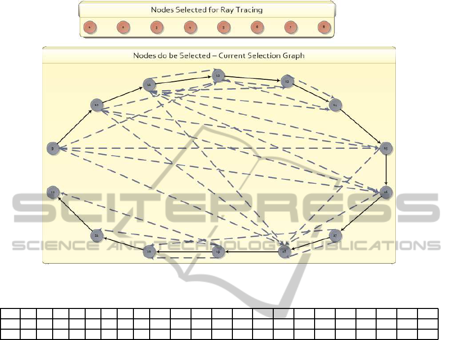
Figure 2: Selection Graph and nodes already selected.
Table 2: Cost (C) and Relevance (R) for the Selection Graph represented in Figure 2.
Node 1 2 3 4 5 6 7 8 9 10 11 12 13 14 15 16 17 18 19 20 21 22
C - - - - - - - - 20 19 18 17 16 15 14 14 13 12 11 10 9 9
R - - - - - - - - 22 21 18 30 31 32 28 27 9 29 1 20 4 3
4.3 Graph Reconstruction Example
Figure 2 represents the selection graph and the se-
lected nodes for the example represented by table 2.
In this example, eight objects are already selected,
and fourteen other objects are waiting to be selected.
The orange circles are objects already selected for ray
trace. Gray circles are objects not selected. Black ar-
rows indicate the node order according to their cost
(C), and the blue dashed arrows point to the N most
relevant (R) objects than the actual node, and with
smaller cost.
When the first object finishes rendering and there
are still time to ray trace other objects, the next object
must be selected. In order to determine the best ob-
ject, the selection graph is traversed until a node with
cost (C), smaller than the cost still available for the
ray trace phase, is found. All the nodes with bigger
costs are moved to the new selection graph in con-
struction to be used during the next frame rendering.
If a node is found, the graph is still traversed in case
this node points to another one with higher relevance
(R).
If there is no time to render a new object, all the
nodes left are moved for the new graph and all the
variables are update for the new graph and the new
frame generation phase.
Figure 3 continue the example of Figure 2. In Fig-
ure 3, the cost available in the ray trace phase is 18.
Node 11 has cost 18 but, according to Table 1, node
14 has more relevance than node 11. When note 14 is
selected, nodes 9 and 10 are re-moved from the graph
and moved for the new graph. The current selection
graph is updated for the next selection. When the time
left for the ray trace stage is not sufficient to render a
new object, the new graph node is constructed for the
next render phase.
5 TESTS AND RESULTS
For the heuristic fine tunning and measurement of
overall performance we use the Sponza scene as the
main environment with many objects spread inside
the scene. Glass and mirror spheres were used as
VISAPP2014-InternationalConferenceonComputerVisionTheoryandApplications
18
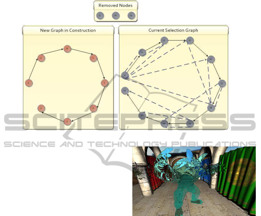
Figure 3: Nodes removed from the selection graph (top), new graph (left) and current selection graph (right).
mandatory objects for ray tracing, in order to guar-
antee that at any given time, there will always be an
object or effect to ray trace.
All the tests were done using a desktop computer
with 16 Gbytes of RAM, an AMD Phenom II X4
965 3.4GHz CPU and a NVIDIA GeForce GTX570
GPU. This machine is running a 64 Bits version of
Microsoft Windows 7 Professional.
In order to achieve frame rates with at least 20
frames per second, the path that the camera traverses
the environmentis fixed, in order to simulate a charac-
ter movement inside the environment. Early random
tests shown the environment need more planning in
order to avoid frame rates bellow 20 frames per sec-
ond.
In order to compare the overall performance, we
run the hybrid renderer twice for the same path. In
the first run, we use ray tracing for all elements in the
scene and for the second run, we use the heuristic to
control the average frame rate in order to avoid drop
the frame rate below 20 fps. Figure 4 represent our
test with an open sky while Figure 5 and 6 show our
indoor tests. In order to render figure 4 in an average
of 20 frames per second, the hybrid renderer decided
to not render the shadows of the Armadillo. Render-
ing the same frame using only ray tracing dropped the
frame rate to an average of 8 frames per second.
With simplified objects, the hybrid renderer is ca-
pable of rendering the path that was used to create fig-
ures 5 and 6 with an average frame rate of 28 and 21
frames per second. Shadows of distant objects where
completely ignored in the two scenes.
Figure 4: Hybrid rendering in ray tracing just the Armadillo
statue and without ray traced shadows.
6 CONCLUSIONS
We have described a heuristic to select objects to be
ray traced in a hybrid rendering pipeline, where the
selected objects are the objects that most contribute
to the visual experience of the user, based on the as-
sumption that objects near the observer and near the
centre of the field of view are more relevant than oth-
ers in different situations. We also offer a strategy to
dynamicallymaintain a graph with the best candidates
to be traced. All the tests and scenarios were planned
to run at a minimum of 20 frames per second.
Unfortunately, the ray tracing phase is still too de-
manding to deal with very complex environments but
we believe that the ray tracing phase will become less
and less demanding for every new version of the Op-
tiX engine and GPU architecture.
TowardsaHeuristicbasedRealTimeHybridRendering-AStrategytoImproveRealTimeRenderingQualityusing
HeuristicsandRayTracing
19
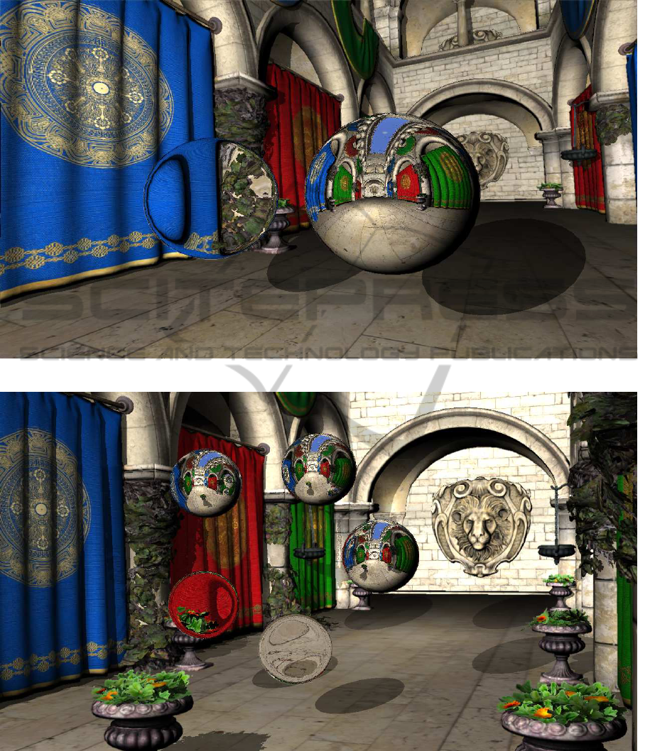
Figure 5: Shadows of distant objects are ignored.
Figure 6: Detailed shadows generated by the ray tracer, when possible.
We are in the middle of our tests and we plan to
try the heuristic based hybrid renderer in many other
scenarios and in order to see if the heuristic is general
enough. We also plan to run stress tests, where the
hybrid renderer will run a very long path, in order to
measure the degradation level, if any, of the selection
graph. New variations of the basic heuristic are also
being planned in order to compare with the original in
complex scenarios.
VISAPP2014-InternationalConferenceonComputerVisionTheoryandApplications
20

REFERENCES
Akenine-M¨oller, T., Haines, E., and Hoffman, N. (2008).
Real-time rendering. A K Peters/CRC Press.
Andrade, P. M. F., Sabino, T. L., Clua, E. W. G.,
and Pagliosa, P. A. (2012). A heuristic to se-
lectively ray trace light effects in real time.
SBGames, pages 2–5. [online] Available from:
http://sbgames.org/sbgames2012/proceedings/papers/
computacao/comp-short
01.pdf.
Bigler, J., Stephens, A., and Parker, S. G. (2006). Design for
parallel interactive ray tracing systems. In Interactive
Ray Tracing 2006, IEEE Symposium on, pages 187–
196. IEEE.
Bikker, J. (2013). Arauna realtime ray tracing & brigade
real-time path tracing. [online] Available from:
http://igad.nhtv.nl/∼bikker/ (Accessed 23 April 2013.
Bikker, J. and van Schijndel, J. (2013). The brigade ren-
derer: A path tracer for real-time games. International
Journal of Computer Games Technology, 2013:1–14.
Cabeleira, J. (2010). Combining rasterization and ray trac-
ing techniques to approximate global illumination in
real-time. Direct.
Cater, K., Chalmers, A., and Ledda, P. (2002). Selective
quality rendering by exploiting human inattentional
blindness: looking but not seeing. In Human Factors,
pages 17–24. ACM.
Cater, K., Chalmers, A., and Ward, G. (2003). Detail to
attention: exploiting visual tasks for selective render-
ing. In EGRWProceedings of the 14th Eurographics
workshop on Rendering Techniques, pages 270–280.
Eurographics Association.
Chalmers, A., Debattista, K., Mastoropoulou, G., and
Paulo dos Santos, L. (2007). There-reality: selective
rendering in high fidelity virtual environments. The
International Journal of Virtual Reality, 6(1):1–10.
Chen, C.-C. and Liu, D. S.-M. (2007). Use of hardware
z-buffered rasterization to accelerate ray tracing. In
Proceedings of the 2007 ACM symposium on Applied
computing SAC07, pages 1046–1050. ACM.
El-Nasr, M. S. and Yan, S. (2006). Visual attention in
3d video games. In Proceedings of the 2006 sympo-
sium on Eye tracking research applications ETRA 06,
page 42. ACM.
Garcıa, A., Avila, F., Murguıa, S., and Reyes, L. (2012).
Interactive ray tracing using the compute shader in di-
rectx 11. GPU Pro 3, 3:353–376.
Green, C. S. and Bavelier, D. (2003). Action video
game modifies visual selective attention. Nature,
423(6939):534–537.
Hertel, S. and Hormann, K. (2009). A hybrid gpu render-
ing pipeline for alias-free hard shadows. Eurographics
2009 Areas Papers, pages 59–66.
Kaplanyan, A. (2010a). CryENGINE 3: Reaching the speed
of light.
Kaplanyan, A. (2010b). Real-time Diffuse Global Illumina-
tionin CryENGINE 3.
Knecht, M., Traxler, C., Winklhofer, C., and Wimmer, M.
(2013). Reflective and refractive objects for mixed re-
ality. IEEE Transactions on Visualization and Com-
puter Graphics, 19(4):576–582.
Lauterbach, C. (2009). Fast hard and soft shadow gener-
ation on complex models using selective ray tracing.
Lloydia Cincinnati.
Livatino, S. (2007). Photorealistic vr games? In 17th Inter-
national Conference on Artificial Reality and Telexis-
tence (ICAT 2007), pages 292–293. IEEE.
Ludvigsen, H. and Elster, A. C. (2010). Real-time ray trac-
ing using nvidia optix. Science, pages 1–4.
Nickolls, J. and Dally, W. J. (2010). The gpu computing
era. Micro, IEEE, 30(2):56–69.
Parker, S. (2009). Interactive ray tracing with the
nvidiaoptix
R
engine. SIGGRAPH.
Parker, S. G., Bigler, J., Dietrich, A., Friedrich, H., Hobe-
rock, J., Luebke, D., McAllister, D., McGuire, M.,
Morley, K., Robison, A., et al. (2010). Optix: a gen-
eral purpose ray tracing engine. ACM Transactions on
Graphics (TOG), 29(4):1–13.
Pritchard, M., Brooks, J., and Geldreich, R. (2004). De-
ferred lighting and shading. In Game Developers Con-
ference.
Rosen, P. (2012). Rectilinear texture warping for fast adap-
tive shadow mapping. In Proceedings of the ACM
SIGGRAPH Symposium on Interactive 3D Graphics
and Games, pages 151–158. ACM.
Sabino, T. L., Andrade, P., Clua, E. W. G., Montenegro, A.,
and Pagliosa, P. (2012). A hybrid gpu rasterized and
ray traced rendering pipeline for real time rendering
of per pixel effects. In Computing-ICEC 2012, 7522,
pages 292–305. Springer.
Sabino, T. L. R., Andrade, P., Lattari, L. G., Clua, E., Mon-
tenegro, A., and Pagliosa, P. A. (2011). Efficient use
of in-game ray-tracing techniques. SBC—Proceedings
of SBGAMES.
Suffern, K. G. (2007). Ray Tracing from the Ground up.
AK Peters.
Sundstedt, V., Debattista, K., Longhurst, P., Chalmers, A.,
and Troscianko, T. (2005). Visual attention for ef-
ficient high-fidelity graphics. In Proceedings of the
21st spring conference on Computer graphics SCCG
05, pages 169–175. ACM.
Thibieroz, N. and Engel, W. (2003). Deferred shading with
multiple render targets.
Wyman, C. and Nichols, G. (2009). Adaptive caustic maps
using deferred shading. In Eurographics 2009, vol-
ume 28. Wiley Online Library.
TowardsaHeuristicbasedRealTimeHybridRendering-AStrategytoImproveRealTimeRenderingQualityusing
HeuristicsandRayTracing
21
