
Interactive Stream Surface Placement
A Hybrid Clustering Approach Supported by Tree Maps
M. Edmunds
1
, R. S. Laramee
1
, R. Malki
1
, I. Masters
1
, Y. Wang
2
, G. Chen
3
, E. Zhang
4
and N. Max
5
1
Swansea University, Wales, U.K.
2
Shenzhen VisuCA Key Lab/SIAT, Shenzhen, China
3
University of Houston, Texas, U.S.A.
4
Oregon State University, Oregon, U.S.A.
5
University of California, Davis, U.S.A.
Keywords:
Automatic Stream Surface Seeding, Data Clustering, Scalar Field Data, Irregular and Unstructured Grids,
Focus + Context Techniques, Flow Visualisation.
Abstract:
The ability of a CFD engineer to study, capture, and visualise 3D flow simulation data is a challenge. Stream
surfaces are a useful tool for visualising 3D flow because of their ability to convey many field attributes from
their structure. It is important that the CFD engineer can interact with, and examine specific characteristics of
the CFD data. We introduce an interactive, cluster based stream surface placement strategy for structured and
unstructured CFD data. A two-phase hybrid clustering algorithm is used to visualise interesting subsets of the
flow. An interactive tree map interface provides a visual overview and enables interactive selection of cluster
details corresponding to interesting features of the data at which to place stream surfaces. We demonstrate
the performance and effectiveness of our interactive framework on a range of flow simulations and provide
domain expert evaluation of the results, providing valuable insight for the CFD engineers.
1 INTRODUCTION
The challenge of visualising CFD (Computational
Fluid Dynamics) simulations include handling large,
unstructured, high dimensional data. This motivates
the need for visualisation techniques to address this
challenge. Although many algorithms have been de-
scribed for the placement of streamlines, relatively
few have been presented for stream surfaces. An im-
portant process for the revealing flow characteristics
is the seeding of such techniques. In this context,
we extend recent work automating the placement of
stream surfaces (Edmunds et al., 2012b) (Edmunds
et al., 2012a) (Edmunds et al., 2011). We study the
surface placement algorithm with emphasis on reduc-
ing the memory requirements and computational time
for the clustering, while working with unstructured
data. Part of the motivation behind our work is a re-
quest from CFD experts to interactively select a sub-
set (or cluster) of the CFD data and obtain more de-
tails. We further study the domain expert require-
ments, developing a visual interface and tools for in-
teractive selection and filtering of cluster representa-
tions of CFD data. The requirements of the domain
experts include: interactive selection of specific areas
of interest, combined visualisation of flow and CFD
data, and visualisation of the evolution of the flow in
both upstream and downstream directions.
In order to accelerate computational speed, and
process large datasets, we introduce an algorithm
for the interactive and semi automatic placement of
stream surfaces by exploiting a two phase clustering
technique that emphasises interesting features of real
world CFD simulation data. We present a novel use
of k-means clustering combined with Density Based
spatial Clustering of Applications with Noise (DB-
SCAN) (Ester et al., 1996). The clustering technique
is used to locate areas of interest for the domain user,
and then to generate seeding curves and surfaces local
to a given cluster, which yield insightful representa-
tions of multi-field CFD data. This allows the inves-
tigation of simulation attributes as they evolve in up
and downstream directions of the flow.
Vector field clustering has been used to show in-
teresting flow features for real world data sets (Peng
et al., 2012). They offer the benefit of not having
to make a binary decision based on the presence of
a feature. K-Means clustering algorithms provide a
347
Edmunds M., Laramee R., Malki R., Masters I., Wang Y., Chen G., Zhang E. and Max N..
Interactive Stream Surface Placement - A Hybrid Clustering Approach Supported by Tree Maps.
DOI: 10.5220/0004691503470355
In Proceedings of the 5th International Conference on Information Visualization Theory and Applications (IVAPP-2014), pages 347-355
ISBN: 978-989-758-005-5
Copyright
c
2014 SCITEPRESS (Science and Technology Publications, Lda.)

general approach to partitioning data. Density based
distance functions are another useful tool for parti-
tioning the domain into smaller subsets. We em-
ploy both of these approaches in our framework for
automatic placement of surfaces in multi-field data
sets. Data samples clustered with k-means in attribute
space may well be separated in Euclidean space. To
deal with this we use the DBSCAN clustering to fur-
ther partition each k-means cluster into sub clusters
separated in Euclidean space. This approach enables
the domain expert to focus on an individual structure
in the flow.
The selection and interaction with large numbers
of clusters, positioned in 3D space, is a challenging
task. A novel approach to enabling selection and in-
teractivity of flow field clusters in 3D space is to cou-
ple them to tree maps. The different cluster attributes
are displayed with the tree map in an interactive visual
interface, for the user to guide the selection of clusters
to place stream surfaces. Tree maps enable the user to
select individual (or groups of) clusters and drill down
the hierarchy to obtain more detail. We illustrate how
to capture the characteristics of the flow field for the
domain users. Our focus pays particular attention to
the performance and flexibility of the clustering com-
bined with the interactive seeding curve placement.
The main benefits and contributions of this paper are:
• Improved computational speed and memory us-
age over recent vector field clustering work, with
the ability to process large, high-dimensional
datasets fast and efficiently.
• An algorithm to partition the flow field using k-
means clustering, providing superior performance
/ memory footprint, and a feature based overview
of the data.
• A technique that subdivides the resulting clusters
based on Euclidean density to support interactive
hierarchical analysis, and semi-automatic stream
surface placement.
• A tree map interface to support interactive selec-
tion of hierarchical clusters in a focus and context
manner.
• The application of these visualisation and inter-
action techniques to real world CFD data with
reviews from the domain experts who prefer the
proposed method over previous techniques.
The rest of this paper is divided into the following
sections. A review of related literature is conducted
in section 2. A detailed presentation of the algorithm
is given in section 3. The results are reviewed in sec-
tion 4. A domain expert evaluation is provided in sec-
tion 5. Conclusions and future work are discussed in
section 6.
2 RELATED WORK
The related work falls into the following: streamline
placement, surface placement strategies, vector field
clustering, and tree maps. We refer the readers to (Ed-
munds et al., 2012c) for a complete overview of flow
visualisation with surfaces.
Clustering. (Xu et al., 2005) survey the topic of
clustering, focusing on scalar clustering algorithms
rooted in statistics, computer science, and machine
learning. Clustering algorithms can be divided into
hierarchical clustering or partition-based clustering.
The (Telea and van Wijk, 1999) algorithm utilises
a hierarchical approach, as does the work by (Ed-
munds et al., 2012b). These algorithms are effec-
tive in providing a simplified representation of a vec-
tor field. However, these algorithms are O(n
2
) com-
plex where n is the number of initial samples. This
has a significant impact on computation and memory
requirements. Alternatively, partitioning algorithms
such as k-means clustering (Bock, 2007) are gener-
ally O(i · k · n) complex (Kogan, 2007), where k is the
number of centroids or means, and i is the number
of iterations. Another partitioning scheme of inter-
est is DBSCAN (Density Based spatial Clustering of
Applications with Noise) (Ester et al., 1996). This
method is particularly useful in partitioning a space
based on the local density, e.g. if two groups of data
are spacially separated, DBSCAN will partition the
two groups into separate clusters. If neighbourhood
connectivity data is stored the overall runtime com-
plexity is O(n · log n). We utilise the k-means clus-
tering to partition a given field from the multi-field
data. We then apply the DBSCAN clustering to each
resultant cluster mean, partitioning the cluster based
on euclidean density.
Tree Maps. (Johnson and Shneiderman, 1991) and
(Shneiderman, 1992) introduce a method for the visu-
alisation of hierarchically structured information. The
technique makes efficient use of the available space
where the full hierarchy is mapped to a rectangular
area (Ward et al., 2010). Large hierarchies can be
rendered completely, while representing a range of se-
mantic information. Following from this, (Van Wijk
and Van De Wetering, 1999) render the rectangles
with shading to improve perception. During the sub-
division, the rectangles are rendered with a simple
shading model. The result is a tree map that consists
of recursive cushions.
(Bruls et al., 2000) introduce the squarified tree
map to generate layouts in which the rectangles ap-
proximate squares. The layout of the children in one
IVAPP2014-InternationalConferenceonInformationVisualizationTheoryandApplications
348

rectangle is a recursive procedure which presents the
rectangles in either horizontal and vertical rows. The
squarified tree map approach provides the domain ex-
pert with interaction and real time feedback. This en-
ables selection of individual clusters, and placement
of stream surfaces in the flow. This is the first work
that we know of that exploits tree maps in order to ad-
dress the challenges of selecting and interacting with
a large number of clusters in 3D space.
3 INTERACTIVE SURFACE
PLACEMENT
This section describes our interactive stream surface
placement algorithm, starting with an overview of the
pipeline illustrated in Figure 1. The algorithm fea-
tures clustering of the selected data field, visualisa-
tion and selection of clusters with a tree map, surface
placement, and rendering. The input to our visuali-
sation framework is an unstructured CFD simulation.
The user selects a single scalar data field a(p) to clus-
ter. The input to the algorithm is a(p) ∈ R, where
a ∈ R, p ∈ Ω and is a 3D regular or unstructured grid
in R
3
.
1. We start by partitioning the selected data field into
k clusters. The k-means algorithm iterates until it
converges to a stable set of means. See Section
3.1.
2. We then use the DBSCAN algorithm to further
subdivide the resulting clusters. The purpose is to
partition any cluster which has spatial separation.
This spatial separation is important when examin-
ing individual features of the flow field. See Sec-
tion 3.2.
3. Next we build a hierarchical tree with k-means
clusters as inner nodes, and the DBSCAN sub
clusters as leaf nodes. This tree is then visualised
with an interactive tree map, displaying meta data
about each cluster. The user can interactively se-
lect any cluster or sub cluster. The selected cluster
is rendered in the main window. See Section 3.3.
4. Once the cluster of interest is selected we calcu-
late the clusters spatial centre, along with the ma-
jor and minor axis of the covariance matrix de-
rived from the cluster’s second moments. These
attributes are used to fit an oriented bounding box
(seeding cuboid) to the cluster. See Section 3.4.
5. Next we compute the seeding curves at the cuboid
boundary planes. See Section 3.5.
6. Stream surfaces are propagated from each of the
seeding curves. Flow attributes may be mapped
to colour and opacity. After the generation of the
stream surfaces, the surface data is rendered using
a number of illustrative techniques to enhance the
perception. See Section 3.6.
3.1 K-Means Clustering
K-Means clustering is a fast, simple, and popular
method for clustering data (Bock, 2007). With rel-
atively low computational requirements and memory
usage compared to hierarchical clustering, it is a good
candidate to solve data partitioning and significantly
reduce the computational and memory requirements.
This algorithm needs no modification to deal with ei-
ther structured or unstructured data.
The procedure provides a simple way to classify a
given data field through a number k of clusters chosen
a priori. The main idea is to define k centroids, one for
each cluster. The next step is to take each grid vertex
p
i
belonging to Ω and associate it with the nearest ini-
tial centroid c (Kogan, 2007). The distance function
d(c, a) is defined as ||c −a||
2
.
3.2 DBSCAN Clustering
The Density-Based spatial Clustering of Applications
with Noise (DBSCAN) algorithm is used for finding
non linear shape structures based on the density (Es-
ter et al., 1996). Once the k-means clustering has con-
verged, the resultant points are neighbouring clusters
in the chosen data field. However this is not necessar-
ily so in euclidean space. Separation of these clusters
into sub clusters in euclidean space is important to
the domain expert when examining distinct features
in the flow field to which the k-means cluster is asso-
ciated. DBSCAN requires two parameters; ε the min-
imum distance to neighbouring points and the mini-
mum number of points required to form a cluster n
min
.
3.3 Cluster Selection with Tree Maps
Hierarchical structures are ubiquitous e.g. family
trees, and directory structures (Kehrer and Hauser,
2012). Many techniques have been proposed to visu-
alise such structures more effectively. However, few
methods have been presented for interacting with a
large cluster hierarchy in 3D space. Tree maps are
an efficient and compact method to display hierarchi-
cal structures. The basis for choosing tree maps is
two fold: First, the CFD domain experts specifically
requested the ability to select any cluster and obtain
more detail. Second, interacting and selecting clus-
ters in a large 3D spatial hierarchy is cumbersome at
best.
We utilise squarified tree maps by (Bruls et al.,
2000). The method is based on tree maps by (Johnson
InteractiveStreamSurfacePlacement-AHybridClusteringApproachSupportedbyTreeMaps
349
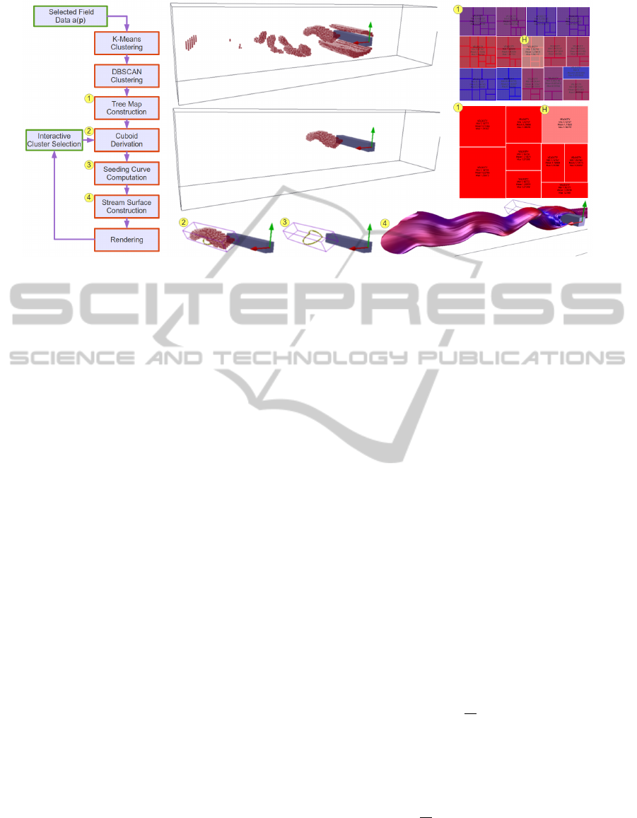
Figure 1: The left image shows our algorithm pipeline. The top centre and right images show a selected k-means cluster.
The selected cluster in the tree map is highlighted grey, and labelled with a ’H’. The centre and centre right images show a
selected DBSCAN sub cluster. The bottom right image shows a cuboid fitted to a selected cluster. The bottom centre image
shows seeding curves derived at the cuboid boundaries. The bottom right image shows the final rendering of the upstream and
downstream surfaces. The dataset shown here has been provided by Tino Weinkauf and used in von Funck et al. for smoke
visualisations (von Funck et al., 2008).
and Shneiderman, 1991) and (Shneiderman, 1992).
The tree map is constructed via recursive subdivision
of an initial rectangle. The size of each sub rectangle
corresponds to the size of the node. Colour and an-
notation is used to provide further information about
the leaves. We build a hierarchical tree with the k-
means clusters represented by the inner nodes. We
then build the leaf nodes of the tree with the DBSCAN
sub clusters of the parent spherical k-means cluster
mean node. Moving the mouse over a node in the tree
map view highlights the cluster vertices within the 3D
spatial view. If the user moves the mouse over a k-
means node, the complete set of cluster vertices are
displayed in the 3D spatial view. Meta data about the
cluster is shown in the tree map view, along with the
DBSCAN children of this cluster. If the user selects
the cluster node, the children are displayed in the tree
view. Again, if the user moves the mouse over a DB-
SCAN node, the sub cluster is displayed in the main
view. Meta data about sub clusters are shown on the
tree map view. (See Figure 2).
The benefits of this method are that user interac-
tion provides feedback about the spatial hierarchies,
filtering the spatial hierarchies to examine specific ar-
eas of interest, and details on demand. This allows the
domain expert to explore and select areas of the data
in a focus and context manner and provides visual
feedback in the linked 3D view. Once an area of in-
terest is selected, the user can examine with the use of
stream surfaces how the attributes of the flow evolve
both upstream and downstream. Stream surfaces are
generated from a seeding cuboid, fitted around the
cluster of interest.
3.4 Cluster Attribute Computation
An object, e.g. an ellipsoid or bounding box, with
nine degrees of freedom, is fitted around the geometry
of a cluster. There are three degrees of freedom for the
centre point position, three for the orientation of the
object axes, and three for the axes lengths.
The object fit provides a good indication of the
global geometry of a cluster’s position, size, and ori-
entation. The centre point position is the average po-
sition of the cluster points. The volume of an object
can be determined from the axis lengths. The orienta-
tion can be determined from the axis directions. The
following is a description of the PCA method used to
derive the cluster attributes. We describe the analytic
and the related discretised version. For any cluster
π(c) the following volume integrals describe its shape
in euclidean space (Jolliffe, 2005) (Reinders, 2001)
(Stroud and Booth, 2001). The Euclidean centre of
π(c):
u
π
=
1
v
π
Z
π
pdv
where p ∈ π(c) is a vertex in 3D euclidean space, and
v
π
is the volume of π(c). We next calculate the second
moment of π(c). This provides us with the covariance
matrix s
π
:
s
π
=
1
v
π
Z
π
(p − u
π
)(p − u
π
)
T
dv
The eigenvectors of the covariance matrix s
π
are three
unit vectors e
1
, e
2
, and e
3
with s
π
e
i
= λ
i
e
i
where
e
i
is the i
th
eigenvector and λ
i
is the corresponding
IVAPP2014-InternationalConferenceonInformationVisualizationTheoryandApplications
350
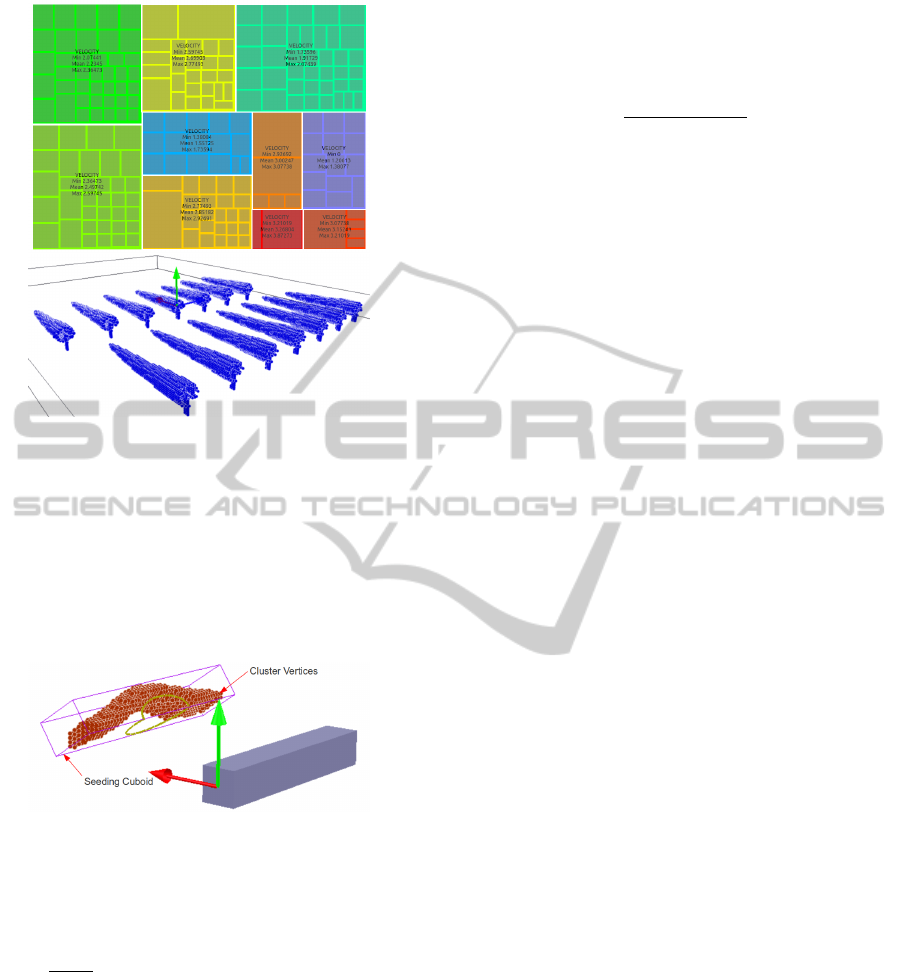
Figure 2: The tree map in the top image shows a high-
lighted cluster (middle right) which can be seen rendered
in the main view (bottom image). The size of the rectangle
is mapped to the size of the cluster, and colour is mapped
to the mean of the cluster. Meta data about the cluster is
overlaid onto the cluster rectangle. The sub clusters gener-
ated from the DBSCAN clustering can also be seen in the
highlighted tree map cluster, and relate to the spacially sep-
arated sub clusters seen in the main view (bottom image).
The colour of the cluster in the bottom image is also mapped
to its mean.
Figure 3: This image illustrates a seeding cuboid fitted to a
cluster in the flow past a cuboid data. The seeding cuboid
is centred at the cluster centre, oriented according to the
eigenvector directions, and is scaled by the eigenvalues.
eigenvalue. The normalised standard deviation σ of
the covariance s
π
in the i
th
eigenvalue direction is
σ
i
=
p
λ
i
/v
π
. To fit a cuboid C to any cluster π(c),
it is centred on u
π
where its size and orientation in
each axis corresponds to the unit eigenvectors e
i
mul-
tiplied by the corresponding normalised standard de-
viation σ
i
. See Figure 3.
3.5 Seeding Cuboid
For the challenge of generating seeding curves be-
tween and inclusive of boundary switch curves, we
compute a scalar field representing the flow exit tra-
jectory from the cuboid boundary C
0
. When the flow
is parallel to the cuboid boundary the scalar is 0.5.
When the flow exits orthogonal to C the scalar is zero,
and when entering is unity. The scalar s is calculated
as follows:
s =
2cos
−1
(
ˆ
n
p
·
ˆ
n
v
)
3.14159
where
ˆ
n
p
is the plane normal,
ˆ
n
v
is the normalised
velocity vector, and cos
−1
(
ˆ
n
p
·
ˆ
n
v
) is given in radi-
ans. This approach reduces the problem to a simple
marching squares (Watson, 1992) isoline extraction.
For a generic vector field using the full sphere of pos-
sible directions, the set of points on the boundary of a
cube, where
ˆ
n
v
·
ˆ
n
p
= 1 or −1 , will be isolated points,
not a curve. Thus we generally use isovalues in the
range [0.95 . . . 0.05]. Next we construct the isolines
from s(C
0
) using marching squares. The vertices re-
quire sequential ordering for use as a seeding curve.
For a more detailed discussion on this technique we
refer the reader to (Edmunds et al., 2011).
3.6 Surface Construction/Rendering
Our work utilises an out of the box solution for gen-
erating stream surfaces. The stream surface is con-
structed with an advancing front scheme first intro-
duced by (Hultquist, 1992). An adaptive Runge-Kutta
4th order integrator is used in the surface construc-
tion. The user can select downstream and upstream
propagation. By default surfaces are terminated when
they leave the domain, enter a periodic orbit, or reach
a pre-determined maximum length. The user has
an option to control the length. A number of tech-
niques are implemented to aid the viewer in percep-
tion of the resulting visualisation. Options include the
use of transparency, colour, and silhouette edge high-
lighting. Transparency in visualisations pose prob-
lems relating to the order of primitive rendering. We
use depth peeling, an order independent transparency
technique presented by (Bavoli and Myers, 2008).
Silhouette edge highlighting is used to help the
viewer in perceiving where the surfaces curve away
from the viewer, and enhance surface edges. Silhou-
ette highlighting utilises a Gaussian kernel in image
space (M
¨
oller and Haines, 2002). Reducing the satu-
ration of colour as the surfaces curve away from the
viewer further enhances the perception of shape (Ed-
munds et al., 2012b).
4 RESULTS
Interaction and exploratory tools are very useful to
the domain expert for the production of insightful and
meaningful visualisations. Our clustering approach
InteractiveStreamSurfacePlacement-AHybridClusteringApproachSupportedbyTreeMaps
351
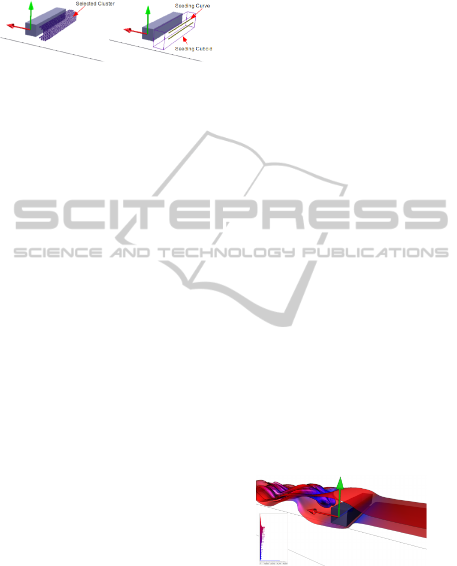
Figure 4: Left image highlights a selected cluster in the re-
gion downstream from the cuboid. The right image shows a
seeding cuboid fitted to the same cluster, with two seeding
curves derived on the rear face.
partitions the domain into meaningful subsets based
on the field of interest. Interacting with the clusters
utilising a tree map is an intuitive approach for investi-
gating the different characteristics of the data. Placing
stream surfaces at the selected areas of interest pro-
vide further feedback about the evolution of a given
attribute upstream and downstream. In the follow-
ing section we discuss our technique applied to a well
known simulation in the community (Camarri et al.,
2005) (von Funck et al., 2008). We then demonstrate
our algorithm applied to a CFD simulation from do-
main experts.
Flow Past A Cuboid. For the clustering process,
velocity magnitude data is chosen for the input. The
number of means are five. Once the clustering pro-
cess is complete the tree map is displayed. From the
tree map the user can see meta data about each clus-
ter describing the velocity range and mean. With size
mapped to cluster size and colour mapped to the clus-
ter mean (in this case mean velocity of the cluster), a
range of information can be inferred. Combined with
the visual representation in the main view, this aids
the user in the selection of a cluster of interest. The
selected cluster is a sub-cluster with a mean velocity
of 0.71 m/s, and a range of 0.58 m/s to 0.78 m/s. See
Figure 4. In the final visualisation in Figure 5, after
the surfaces are propagated from the seeding cuboid,
it can be seen how the area of interest interacts with
the upstream and downstream flow. An isovalue of
0.95 is used to generate the seeding curves.
Visualisation of Marine Turbine CFD Simulation.
A marine turbine makes use of kinetic energy avail-
able in moving water, similar in concept to a wind
turbine being powered by the wind. This applica-
tion is gaining popularity due to the relative advan-
tages marine turbines offer. Modelling and simulation
are carried out to investigate how the flow past a ma-
rine turbine is affected and thus develop a better and
more efficient marine turbine system. The engineers
researching this field are investigating the system of
turbine arrays and their interaction with each other
in different spatial arrangements. The velocity wake
flowing downstream of a marine turbine may inter-
act with the downstream turbines. The goal is to find
the optimal layout to pack the turbines into a given
space and maximise the energy output, while manag-
ing the environmental effect and durability (Masters
et al., 2011) (Malki et al., 2012). The velocity wake
and pressure can have a major impact on the envi-
ronment, and the marine turbines. The marine turbine
multi-field data is defined on an unstructured irregular
grid. For the clustering process, pressure data is cho-
sen for the input. The number of means are five. A set
of sub-clusters are selected, and an isovalue of 0.05 is
used to generate the seeding curves. The final visual-
isation can be seen demonstrating an optimal solution
for the array layout. See Figure 6. We also illustrate
a sub-optimal layout where the turbine wake signifi-
cantly interferes with neighbouring and downstream
turbines. See Figure 7.
5 EVALUATION
To evaluate our work we compare and contrast with
recent work in this area. Our algorithm performs well
when compared to the hierarchical clustering of (Ed-
munds et al., 2012b). The hierarchical clustering is
O(n
2
), compared with our algorithm; O(i · k · n), and
O(n ·log n), for the k-means and DBSCAN clustering
respectively. Our algorithm is implemented in C++
and QT4 on a PC with an NVIDIA GeForce GTX480,
an Intel quad core 2.8GHz CPU with 8GB RAM. The
bottleneck in the performance of our algorithm is the
clustering as seen in Table 1. The time for tree map
generation is in the 7-65[ms] range. The calculation
of the cluster attributes and seeding cuboid fitting is
in the 18-174[ms] range. The performance of stream
surface rendering is comparable to previous work e.g.
(Born et al., 2010), (Hummel et al., 2010), and (Ed-
munds et al., 2012b). The memory usage for our ap-
Figure 5: This visualisation demonstrates stream surfaces
seeded from the locations illustrated in Figure 4. We capture
the singularity at the centre of a double vortex downstream
of the cuboid. The surfaces are rendered with illustrative
techniques to enhance the perception. Colour is mapped to
velocity, see inset colour map histogram.
IVAPP2014-InternationalConferenceonInformationVisualizationTheoryandApplications
352
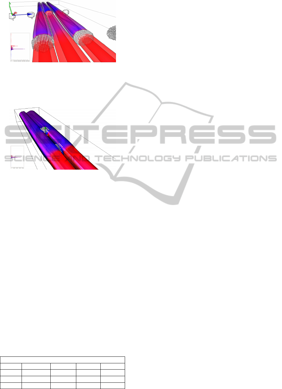
Figure 6: This visualisation demonstrates stream surfaces
seeded from the clusters situated in front of the turbine
blades. Pressure is used for the clustering, while colour
is mapped to velocity which enables tracking the velocity
wake edge effect on neighbouring and downstream marine
turbines.
Figure 7: This visualisation illustrate a sub-optimal layout.
Velocity spikes can be seen neighbouring the downstream
turbine. We use the same parameters as in Figure 6.
proach is proportional to the size of the data set e.g.
n, where n is the number of initial samples. We store
only one integer per vertex to reference which cluster
it belongs to. The hierarchical approach stores vec-
tor data, location data, cluster size data, cumulative
error data, and neighbourhood/connectivity informa-
tion at each node in the binary tree. The quantity of
nodes is 2n − 1. The hybrid clustering approach is
generally one order of magnitude faster than its pre-
decessor. The input to our algorithm is: the selec-
tion of which data field to cluster, the number of cen-
troids (calculated from the required attribute ranges
by domain engineer), and a seeding cuboid isovalue
of 0.05, 0.5, or 0.95 (outflow, boundary switch curves,
and inflow respectively). This set of input parame-
Table 1: Clustering performance of a range of simulations.
All are regular grid data except the Turbine data, which is
an unstructured tetrahedral grid outputted from Tecplot 360
(Tecplot, ). For consistency we use 5 means for the timings.
Note: For reference the last column contains comparative
times from (Edmunds et al., 2012b).
Clustering Performance
Data Nodes No.Means Time[ms] Time[ms]
Cuboid 192x64x48 5 487 6,898
Turbine 3,693,867 5 5,923 n/a
Isabel 500
2
x100 5 30,724 542,452
ters is greatly simplified compared to previous work
(Edmunds et al., 2012b). The flexibility of using tree
maps to select individual clusters of interest is invalu-
able to the domain engineer. The visual and con-
textual feedback this approach affords is relevant to
the domain engineer’s work flow. The domain engi-
neer can derive the input, then visualise the precise
features of interest. The focus and context nature
of the clustering combined with the stream surfaces
re-enforce the visual feedback, providing an intuitive
and meaningful environment focusing on data explo-
ration. When selecting areas of interest, the previ-
ous algorithm in (Edmunds et al., 2012b) performed
poorly when applied to the marine turbine data. This
may be the result of insignificant flow characteristics
within the vector field. The seed locations became too
dense when trying to capture the particular areas of in-
terest, resulting in a cluttered incomprehensible visu-
alisation. In contrast, the interaction in our approach
enabled the domain engineer to select precisely the
location to place stream surfaces for a more focused
evaluation. In contrast to the work by (Edmunds et al.,
2011), we generate seeding curves on the boundary of
a seeding cuboid fitted to a cluster in euclidean space.
This enables very localised exploration of the flow
field. We also modify the scalar field computation.
This has the effect of producing a smoother transition
between the range of isovalues.
Domain expert feedback. This work is carried out
in close collaboration with a team of CFD experts.
One of the goals of this work is to provide CFD ex-
perts with a visual interface and tools for interac-
tive exploration of multi-field unstructured CFD data.
Specifically; interactive selection of specific areas of
interest, the combined visualisation of flow and dif-
ferent CFD data fields, visualisation of the evolution
of the flow. This section summarises their feedback.
The interactive stream surface placement method de-
scribed in this paper is unique compared to similar
approaches evaluated previously in that it facilitates
a much greater level of control to the user over the
placement of streamed surfaces. One particularly use-
ful feature is the ability of the user to precisely isolate
different regions of the domain and evaluate them in-
dividually. Furthermore, user access to the tree map
provides a useful added feature promoting control, in-
formation feedback, and enabling the user to evaluate
the sensitivity of different fields of the data. In the
context of multiple marine turbine arrays with some
level of repetition in the array layout, this is useful
as it avoids repetition of stream surface features that
may occur around similarly spaced turbines within the
layout. Furthermore, the ability to individually con-
InteractiveStreamSurfacePlacement-AHybridClusteringApproachSupportedbyTreeMaps
353

trol the illustrative techniques of a number of stream
surfaces within the same region of the domain en-
ables the user to tweak the final image to improve
clarity, and focus attention on certain layers. This
work provides valuable insight into the domain expert
CFD data, as visualisation tools rarely come equipped
with quantitative analysis features which are usually
of more use to engineers.
6 CONCLUSIONS
The goal of this work is to improve computational
performance, memory footprint, exploratory flexibil-
ity, robustness of flow visualisation across different
multi-field flow data including unstructured data, and
intuitive feedback on the fly in an interactive envi-
ronment for detailed examination of the multi-field
data. We improve the performance and memory us-
age, while providing an environment and tools for the
domain engineer to visualise multi-field CFD data.
We demonstrate a novel application of k-means and
DBSCAN clustering to provide focus and contextual
information when combined with tree map interac-
tion. The fast performance brings vector field clus-
tering a large step forward towards clustering of un-
steady flow data. The novel use of a seeding cuboid
fitted to clusters for the placement of stream sur-
faces provides intuitive feedback about the evolution
of the selected attributes both upstream and down-
stream from the location of interest. We compare and
contrast with other recent work in this field, provid-
ing feedback from domain experts utilising our frame-
work who conclude that this technique is a signifi-
cant improvement over recent work in this area. Dur-
ing our study we examined the possibility of utilis-
ing multi-field clustering with the intent of removing
the need for the user to select a data field of interest.
Because, within our target domain, the various data
fields are dependant data, multi-field clustering does
not produce results significantly different from clus-
tering a single field. The domain experts preferred
the flexibility of selecting the fields of interest.
REFERENCES
Bavoli, L. and Myers, K. (2008). Order Independent Trans-
parency with Dual Depth Peeling. NVIDIA Developer
SDK 10.
Bock, H.-H. (2007). Clustering Methods: A History of
k-Means Algorithms. In Brito, P., Cucumel, G.,
Bertrand, P., and Carvalho, F., editors, Selected Con-
tributions in Data Analysis and Classification, Stud-
ies in Classification, Data Analysis, and Knowledge
Organization, pages 161–172. Springer Berlin Heidel-
berg.
Born, S., Wiebel, A., Friedrich, J., Scheuermann, G., and
Bartz, D. (2010). Illustrative Stream Surfaces. IEEE
Transactions on Visualization and Computer Graph-
ics, 16(6):1329–1338.
Bruls, M., Huizing, K., and Van Wijk, J. (2000). Squar-
ified treemaps. In Data Visualization, pages 33–42.
Citeseer.
Camarri, S., Salvetti, M.-V., Buffoni, M., and Iollo, A.
(2005). Simulation of the three-dimensional flow
around a square cylinder between parallel walls at
moderate Reynolds numbers. In XVII Congresso di
Meccanica Teorica ed Applicata.
Edmunds, M., Laramee, R., Chen, G., Zhang, E., and Max,
N. (2012a). Advanced, Automatic Stream Surface
Seeding and Filtering. In Theory and Practice of Com-
puter Graphics, pages 53–60.
Edmunds, M., Laramee, R., Malki, R., Masters, I., Croft,
T., Chen, G., and Zhang, E. (2012b). Automatic
Stream Surface Seeding: A Feature Centered Ap-
proach. Computer Graphics Forum, 31(3.2):1095–
1104.
Edmunds, M., Laramee, R. S., Chen, G., Max, N., Zhang,
E., and Ware, C. (2012c). Surface-Based Flow Visu-
alization. Computers & Graphics, 36(8):974 – 990.
Edmunds, M., McLoughlin, T., Laramee, R. S., Chen, G.,
Zhang, E., and Max, N. (2011). Automatic Stream
Surfaces Seeding. In EUROGRAPHICS 2011 Short
Papers, pages 53–56, Llandudno, Wales, UK.
Ester, M., Kriegel, H., Sander, J., and Xu, X. (1996). A
Density-Based Algorithm for Discovering Clusters in
Large Spatial Databases with Noise. In Proceedings of
the 2nd International Conference on Knowledge Dis-
covery and Data mining, volume 1996, pages 226–
231. AAAI Press.
Hultquist, J. P. M. (1992). Constructing Stream Surfaces in
Steady 3D Vector Fields. In Proceedings IEEE Visu-
alization ’92, pages 171–178.
Hummel, M., Garth, C., Hamann, B., Hagen, H., and Joy, K.
(2010). IRIS: Illustrative Rendering for Integral Sur-
faces. IEEE Transactions on Visualization and Com-
puter Graphics, 16(6):1319–1328.
Johnson, B. and Shneiderman, B. (1991). Tree-maps: A
Space-Filling Approach to the Visualization of Hier-
archical Information Structures. In Proceedings of the
2nd conference on Visualization ’91, VIS ’91, pages
284–291, Los Alamitos, CA, USA. IEEE Computer
Society Press.
Jolliffe, I. (2005). Principal Component Analysis. Wiley
Online Library.
Kehrer, J. and Hauser, H. (2012). Visualization and Vi-
sual Analysis of Multi-faceted Scientific Data: A Sur-
vey. IEEE Transactions on Visualization and Com-
puter Graphics.
Kogan, J. (2007). Introduction to Clustering Large and
High-Dimensional Data. Cambridge University Press.
Malki, R., Williams, A., Togneri, M., and Masters, I.
(2012). A Coupled Blade Element Momentum: Com-
putational Fluid Dynamics Model for Evaluating Tidal
IVAPP2014-InternationalConferenceonInformationVisualizationTheoryandApplications
354

Stream Turbine Performance. Applied Mathematical
Modelling, Available online 16 August 2012.
Masters, I., Chapman, J., Orme, J., and Willis, M. (2011). A
Robust Blade Element Momentum Theory Model For
Tidal Stream Turbines Including Tip And Hub Loss
Corrections. Proceedings of the Institute of Marine
Engineering, Science and Technology Part A, Journal
of Marine Engineering and Technology, 10(1):25–35.
M
¨
oller, T. and Haines, E. (2002). Real-Time Rendering. A.
K. Peters Limited, 2 edition.
Peng, Z., Grundy, E., Laramee, R. S., Chen, G., and Croft,
N. (2012). Mesh-Driven Vector Field Clustering and
Visualization: An Image-Based Approach. IEEE
Transactions on Visualization and Computer Graph-
ics, 18(2):283–298.
Reinders, K. F. J. (2001). Feature-Based Visualisation of
Time-Dependant Data. Technische Universiteit Delft.
Shneiderman, B. (1992). Tree Visualization with Tree-
Maps: 2-d Space-Filling Approach. ACM Trans.
Graph., 11(1):92–99.
Stroud, K. and Booth, D. (2001). Engineering Mathematics.
Industrial Press Inc.
Tecplot. Tecplot 360. http:// www.tecplot.com/. Accessed:
March 2013.
Telea, A. and van Wijk, J. J. (1999). Simplified Represen-
tation of Vector Fields. In Proceedings IEEE Visual-
ization ’99, pages 35–42.
Van Wijk, J. and Van De Wetering, H. (1999). Cushion
treemaps: Visualization of hierarchical information.
In Information Visualization, 1999.(Info Vis’ 99) Pro-
ceedings. 1999 IEEE Symposium on, pages 73–78.
IEEE.
von Funck, W., Weinkauf, T., Theisel, H., and Seidel,
H.-P. (2008). Smoke surfaces: An interactive flow
visualization technique inspired by real-world flow
experiments. IEEE Transactions on Visualization
and Computer Graphics (Proceedings Visualization
2008), 14(6):1396–1403.
Ward, M., Grinstein, G., and Keim, D. (2010). Interactive
Data Visualization. A K Peters.
Watson, D. F. (1992). Contouring. Pergamon Press.
Xu, R., Wunsch, D., et al. (2005). Survey of Clustering
Algorithms. Neural Networks, IEEE Transactions on,
16(3):645–678.
InteractiveStreamSurfacePlacement-AHybridClusteringApproachSupportedbyTreeMaps
355
