
3D-NCuts: Adapting Normalized Cuts to 3D Triangulated Surface
Segmentation
Zahra Toony
1
, Denis Laurendeau
1
, Philippe Gigu`ere
2
and Christian Gagn´e
1
1
Computer Vision and System Laboratory, Department of Electrical and Computer Engineering, Universit´e Laval,
Qu´ebec, QC, Canada
2
Department of Computer Science and Software Engineering, Universit´e Laval, Qu´ebec, QC, Canada
Keywords:
3D Segmentation, Spectral 3D Segmentation, Primitive Extraction from Mesh Models, Clustering.
Abstract:
Being able to automatically segment 3D models into meaningful parts is an important goal in 3D shape pro-
cessing. In this paper, we are proposing a fast and easy-to-implement 3D segmentation approach, which is
based on spectral clustering. For this purpose, we define an improved formulation of the similarity matrix
which allows our algorithm to segment both free-form and CAD (Computer Aided Design) 3D models. In 3D
space, different shapes, such as planes and cylinders, have different surface normal distributions. We defined
the similarity of vertices based on their normals which can segment a 3D model into its geometric features.
Results show the effectiveness and robustness of our method in segmenting a wide range of 3D models. Even
in the case of complex models, our method results in meaningful segmentations. We tested our segmentation
approach on real data segmentation, in the presence of noise and also in comparison with other methods which
provided good results in all cases.
1 INTRODUCTION
In the early 1980s, availability of precise 2D and 3D
cameras has opened a new field of computer vision,
3D image acquisition and processing (Blais, 2004).
Nowadays, this field has many different applications
such as assembly, inspection, Computer-aided Design
(CAD), reverse engineering, mechanical engineering,
medicine, and entertainment.
Standard 2D cameras produce 2D images from the
surface of objects, in either black-and-white or color,
but 3D cameras provide information on the geome-
try of the object surface. Today, some 3D cameras
can acquire both the appearance and geometry of ob-
jects concurrently. This results in many 2D process-
ing approaches applied on 3D images: 3D mesh com-
pression (Yu et al., 2012; Jiang et al., 2012; Carnero
et al., 2012), 3D skeleton extraction (Sam et al., 2012;
Zhang et al., 2012; Benhabiles et al., 2012), 3D object
recognition (Karim Baareh et al., 2012; Huber et al.,
2004; Murase and Nayar, 1995; Selinger and Nelson,
1999), and 3D segmentation (Xiao et al., 2011; Liu
and Zhang, 2004; Lavou´e et al., 2012) are instances
of such extensions of 2D approaches to 3D.
One of the challenges in shape processing and un-
derstanding is to segment a 3D object into meaningful
parts (Ning et al., 2010). This implies segmenting a
3D shape, not based on distances, but rather based on
its properties to obtain a result close to a manual seg-
mentation. Many applications, such as object recog-
nition, modelling, or compression depend on mean-
ingful segmentation (Kalogerakis et al., 2010). In
some other applications, segmentation is used to la-
bel parts of the shapes; many of these approaches use
manually segmented shapes. For example, in a human
body one could distinguish “arm”, “leg”, and “head”
from each other (Kalogerakis et al., 2010). Ground-
truth databases for segmentation of 3D-meshes were
created recently, (Benhabiles et al., 2009; Chen et al.,
2009). They offer the opportunity of analyzing and
learning mesh segmentation quantitatively (Benhab-
iles et al., 2011).
Based on what is presented in (Shamir, 2008), al-
gorithms in 3D mesh segmentation can be catego-
rized into five groups while the paper by (Agathos
et al., 2007) presented a more detailed classi-
fication of 3D mesh segmentation methods into
twelve groups: “Region growing”, “Watershed-
based”, “Reeb graphs”, “Model-based”, “Skeleton-
based”, “Clustering”, “Spectral analysis”, “Explicit
Boundary Extraction”, “Critical points-based”, “Mul-
tiscale Shape Descriptors”, “Markov Random Fields”
144
Toony Z., Laurendeau D., Giguère P. and Gagné C..
3D-NCuts: Adapting Normalized Cuts to 3D Triangulated Surface Segmentation.
DOI: 10.5220/0004692101440152
In Proceedings of the 9th International Conference on Computer Graphics Theory and Applications (GRAPP-2014), pages 144-152
ISBN: 978-989-758-002-4
Copyright
c
2014 SCITEPRESS (Science and Technology Publications, Lda.)

and “Direct segmentation”. To find more details on
methods in each category refer to (Shamir, 2008;
Agathos et al., 2007). Each of these groups can per-
form the segmentation in two main ways: surface-
based and part-based. A surface-based 3D mesh seg-
mentation method attempts to segment a model into
different regions under some criteria that can be esti-
mated by simple shapes such as planes or cylinders.
On the other hand, a part-based approach attempts to
segment it into meaningful volumetric parts (Agathos
et al., 2007).
In this work, we study the segmentation of a 3D
model with a spectral analysis approach in a surface-
based paradigm. Spectral analysis methods are based
on a similarity matrix. Our focus here is to define a
similarity matrix that avoids thresholding and works
without using training data. We introduce two param-
eters in order to improve the quality of segmentation
results. It can discriminate different parts with differ-
ent geometries very well, thus resulting in meaningful
mesh segmentation.
The rest of the paper is organized as follows. The
related works are represented in Section 2. In Sec-
tion3, we explain our problem and present the details
of our novel 3D Normalized Cuts approach. Section 4
shows the efficiency of our approach and gives the ex-
perimental results obtained in different situations and
in comparison with other methods. Finally, we con-
clude the paper in Section 5.
2 RELATED WORK
Conducting a meaningfulsegmentation of a 3D model
is generally application dependent. In our case, we
call a segmentation meaningful when it can separate
different geometries from each other as a human does.
Among different types of mesh segmentation meth-
ods, spectral analysis has attracted much attention.
The theory of spectral graphs was introduced
by (Chung, 1997) and was then applied on image seg-
mentation by (Shi and Malik, 2000) as Normalized
Cuts (NCuts). 3D spectral analysis approaches first
define a similarity matrix on the data, based on prop-
erties of mesh connectivity, geometry, etc. Then, a
Laplacian matrix is computed based on the defined
similarity and its eigenvectors are determined in or-
der to segment the 3D model. Since the Laplacian
matrix and eigenvectors are found based on the sim-
ilarity matrix, the most important step of the spectral
analysis methods is how the similarity is defined such
that good segmentations are then obtained.
In 2004, Liu and Zhang (Liu and Zhang, 2004)
applied spectral analysis on 3D models. They de-
fined the similarity matrix as the likelihood that faces
belong to the same segment. In order to prevent
merging faces with different concavities, they used
the distance matrix presented in (Shlafman et al.,
2002; Katz and Tal, 2003). They constructed the
normalized similarity matrix on the faces and then
identified the k eigenvectors with the largest asso-
ciated eigenvalues for further processing. Finally,
they applied k-means on the processed eigenvectors.
They segmented a model by emphasizing concavities,
which sometimes resulted in segmenting unmean-
ingful concavities (Agathos et al., 2007). Another
method (Zhang and Liu, 2005) used the same similar-
ity matrix with recursive spectral cut and Nystr¨om ap-
proximation (Fowlkes et al., 2004), which gave them
the opportunity of defining a partial similarity ma-
trix. The extracted eigenvectors are then used in a
line search algorithm to find the most prominent cut
in order to segment the 3D model. In (Liu and Zhang,
2007), a spectral analysis algorithm based on spectral
embedding and 2D contour analysis was proposed.
The 3D model was projected into the 2D domain in
order to apply contour analysis. The algorithm re-
quired that some parameters be selected, and tended
to fail in the presence of noise.
Some other types of segmentation algorithms
are based on region growth. In these methods, a
seed point is first selected and then grown, in or-
der to find final regions. This often leads to over-
segmentation (Zhang et al., 2002). Watershed-based
approaches are also subject to over-segmentation of
the 3D models (Agathos et al., 2007).
Some other methods, such as Randomized
Cuts (Golovinskiy and Funkhouser, 2008), take the
advantages of using different segmentation meth-
ods to gain both random and non-random features.
In order to segment a 3D model, Golovinskiy and
Funkhouser (Golovinskiy and Funkhouser, 2008)
generate a pool of segmented parts using different ap-
proaches such as k-means (Shlafman et al., 2002),
hierarchical Normalized Cuts and Min Cuts. After-
wards, based on the reputation of each edge on a seg-
mentation boundary, they define a “partition function”
on edges. The “consistent cuts” are then found and the
model is segmented through these cuts.
For the k-means approach, they set the number
of clusters and repeat the k-means algorithm several
times in order to generate different segmentation re-
sults. In the hierarchical Normalized Cuts method,
they start with every face in a separate segment and
then try to merge them based on an area-normalized
cut cost function until the desired number of clusters
is obtained. The cost function is the sum of the cut
costs of segments divided by their areas. They are
3D-NCuts:AdaptingNormalizedCutsto3DTriangulatedSurfaceSegmentation
145

using this cost function, called modified version of
Normalized Cuts, instead of using only the cost of all
edges in a segment which is utilized as Normalized
Cuts in (Shi and Malik, 2000). This algorithm is re-
peated to obtain different results. Finally, in the Min
Cuts approach a set of k seeds is selected and a weight
value is defined for each edge in order to maintain the
cuts at a large distance from the seeds. This method is
also repeated to provide more different segmentation
results.
In (Lai et al., 2008) a random walk approach is
utilized in order to achieve a mesh segmentation. The
authors compute the dual graph of the mesh and se-
lect the seeds automatically; the numbers of seeds are
greater than the desired number of clusters. They then
try to associate each face with a seed with the high-
est probability which results in an over segmented
mesh. Hence, a hierarchical method is then applied
to merge the similar segments based on the length of
common boundaries and overall perimeter of adjacent
segments (Chen et al., 2009).
The hierarchical fitting primitive approach that is
proposed in (Attene et al., 2006) considers each face
as a segment and starts to merge them until the de-
sired number of clusters is obtained. At each itera-
tion, a primitive like plane, sphere and etc. is fitted on
each pair of faces and then the best fitted pair will be
merged as a segment (Chen et al., 2009).
Another approach which is called Shape Diameter
Function (SDF) (Shapira et al., 2008) defines a scalar
function for every face of the mesh and produces a 1-
D histogram. Then, a Gaussian Mixure Model is ap-
plied on the histogram to fit k Gaussian functions on
each face and determine the probability of assigning
faces to each SDF cluster. Finally an alpha-expansion
graph cut method is used to minimize a defined en-
ergy function in order to find the appropriate segmen-
tation. This method determines the number of clusters
automatically (Chen et al., 2009).
Recently, a mesh segmentation method for CAD
models was presented in (Xiao et al., 2011). At first,
the CAD model is clustered into sparse and dense
triangle regions. Using the Gauss map of triangular
faces and Hough transformation, sparse triangle re-
gions are separated into planar regions, cylindrical re-
gions and conical regions. Dense triangle regions are
also segmented by a mean shift operation which is
applied on the mean curvature field of mesh surfaces.
One of the problems of this method is that it deals
poorly with planar regions composed of non-uniform
parts combining sparse and dense triangulations. This
method will split the plane at first, without consider-
ing the geometry of the surface before splitting.
There are also some 3D segmentation methods
based on learning algorithms (Kalogerakis et al.,
2010; Benhabiles et al., 2011), which require a
database of labeled meshes, a constraint that cannot
be satisfied in many cases. Learning-based meth-
ods might achieve better segmentation results than
other methods, however our approach does not use
any training step or training data but rather consid-
ers the differences between geometries. As we aim at
applying Normalized Cuts (Shi and Malik, 2000) in
3D space, the next sections explain the details of this
method in 2D space.
2.1 2D-NCuts
Normalized Cuts (NCuts) (Shi and Malik, 2000) as-
sumes that a 2D model is described as a graph G =
(V,E), where V is the set of vertices in our model and
E is the set of edges (which transposes in 3D as a set
of faces). The cut, or degree of dissimilarity between
two segments, A and B, can be found by defining
cut(A,B) =
∑
u∈A,v∈B
w(u,v), (1)
where, w(u,v) is the similarity between vertex u and v.
Normalized Cuts aims at minimizing the Ncut value
Ncut(A,B) =
cut(A,B)
assoc(A,V)
+
cut(A,B)
assoc(B,V)
, (2)
where, assoc(A,V) =
∑
u∈A,t∈V
w(u,t) is the total simi-
larity from all vertices in A to all vertices in the graph.
This minimization is achieved by solving the follow-
ing generalized eigenvalue system:
(D− W)y = λDy, (3)
where, W is the matrix of similarity between each pair
of vertices and D is a diagonal matrix with:
d(i,i) =
∑
j
w(i, j). (4)
After solving Equation (3), the eigenvector related
to the second smallest eigenvalue of the system is se-
lected. It is claimed that this eigenvector keeps two
vertices i and j in a segment when they have a large
similarity value (large w(i,j)). The problem then con-
sists in determining the splitting point of the eigen-
vector in such a way that the cut value between the
two split parts is minimized. Shi and Malik presented
an optimized loop for achieving this. Another way of
splitting the eigenvector into different parts is apply-
ing a clustering method, such as k-means, to segment
the vector into different regions.
GRAPP2014-InternationalConferenceonComputerGraphicsTheoryandApplications
146
3 PROPOSED IMPROVEMENTS
TO NCUTS
Our goal is to separate a 3D model into meaningful
parts. We desire to detect different parts based on dif-
ferent geometric primitives such as planes, cylinders,
cubes, and rods. So, the differences between these ge-
ometric primitives must be described through a simi-
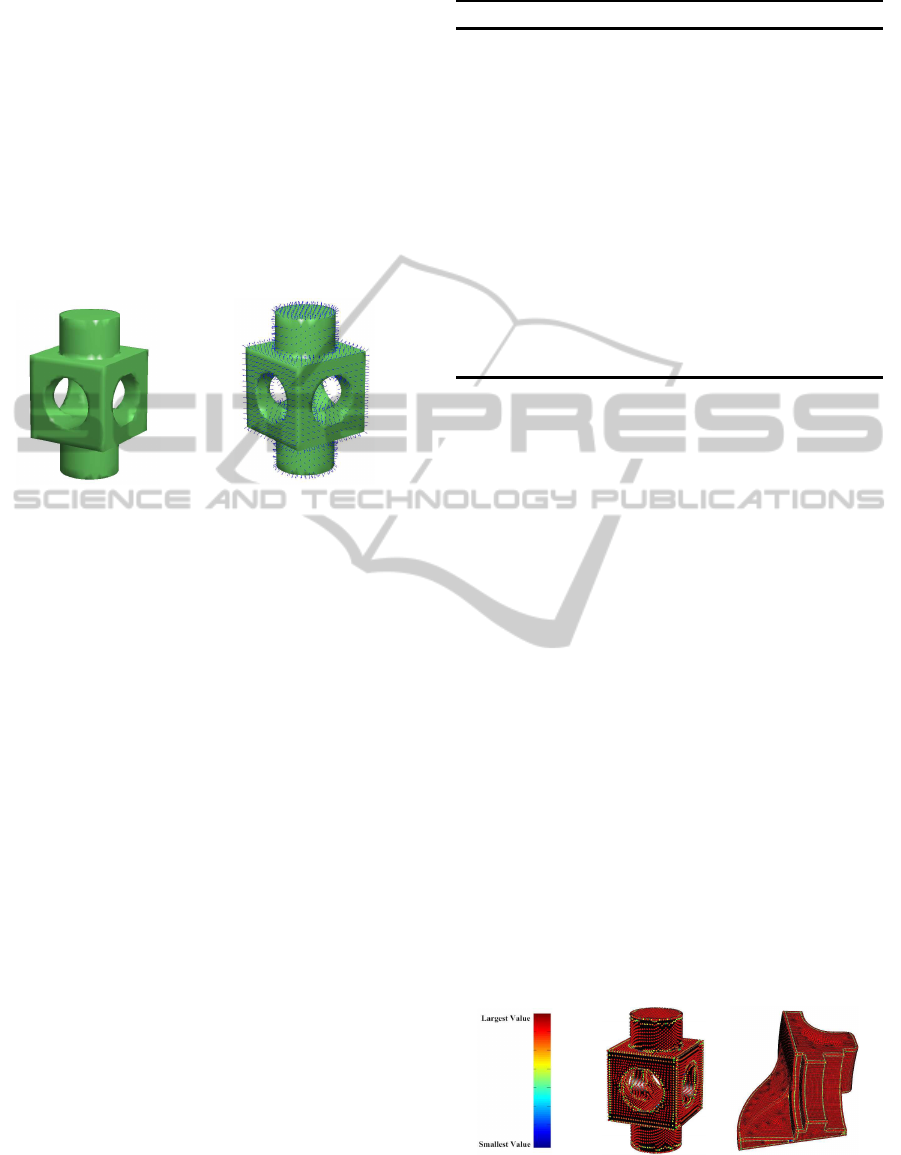
larity matrix. In 3D space, it is clear that all vertices
on a plane have normals in the same direction; all ver-
tices on a cylinder have normals rotating uniformly on
a circle, as can be seen in Figure 1b.
(a) (b)
Figure 1: (a) 3D model, (b) normals to the surface of 3D
model.
Therefore we argue that defining the similarity
based on normals is a good strategy to discriminate
and to separate 3D geometric primitives. We thus de-
fine the similarity matrix as a relation between normal
vectors that can reveal sharp edges and boundaries
(see Figure 2). The similarity between two vertices
is then defined as:
w(i, j) = cos ≺ (~n
i
, ~n
j
), (5)
where, ~n
i
and ~n
j
are normal vectors at vertices i and
j, respectively. As shown in Figure2, we observe
large values of w(i,j) where surface normals are simi-
lar (red), but really small values at the boundaries be-
tween primitives(green) which can help us to separate
different primitives. With this definition of similar-
ity matrix, we then solve an eigenvalue system in or-
der to find the segmentation results. This contrast the
approach proposed in (Golovinskiy and Funkhouser,
2008), where they used the modified Normalized Cuts
idea to find the cost function of a hierarchical clus-
tering approach in order to merge faces. Here, we
produce the segmentation on vertices which, with an
accurate definition of normals, can else be applicable
to point clouds.
The next sections present the details of our ap-
proach for 3D models.
Algorithm 1: Proposed 3D-NCuts.
Input: similarity matrix W, diagonal matrix D and
number of clusters k.
1. Compute the similarity matrix W,
w(i, j) =
cos ≺ (~n
i
, ~n
j
) if i and j are connected by an edge
0 otherwise
2. Evaluate the diagonal matrix D, d(i, i) =
∑
j
w(i, j).
3. Solve the following generalized eigensystem,
(D− W)y = λDy.
4. Suppose V
eig
as a matrix of the k eigenvectors
associated with the k smallest eigenvalues.
5. Apply a clustering method, such as k-means, on V
eig
to
achieve k segments.
Output: Clusters C
1
,C
2
,...,C
k
.
3.1 Our approach: 3D-NCuts
As mentioned in Section 2.1 the Normalized Cuts al-
gorithm begins by defining a similarity matrix on 3D
data. Here we applied this method on 3D shapes and
brought some modifications to the basic algorithm as
presented in Algorithm 1.
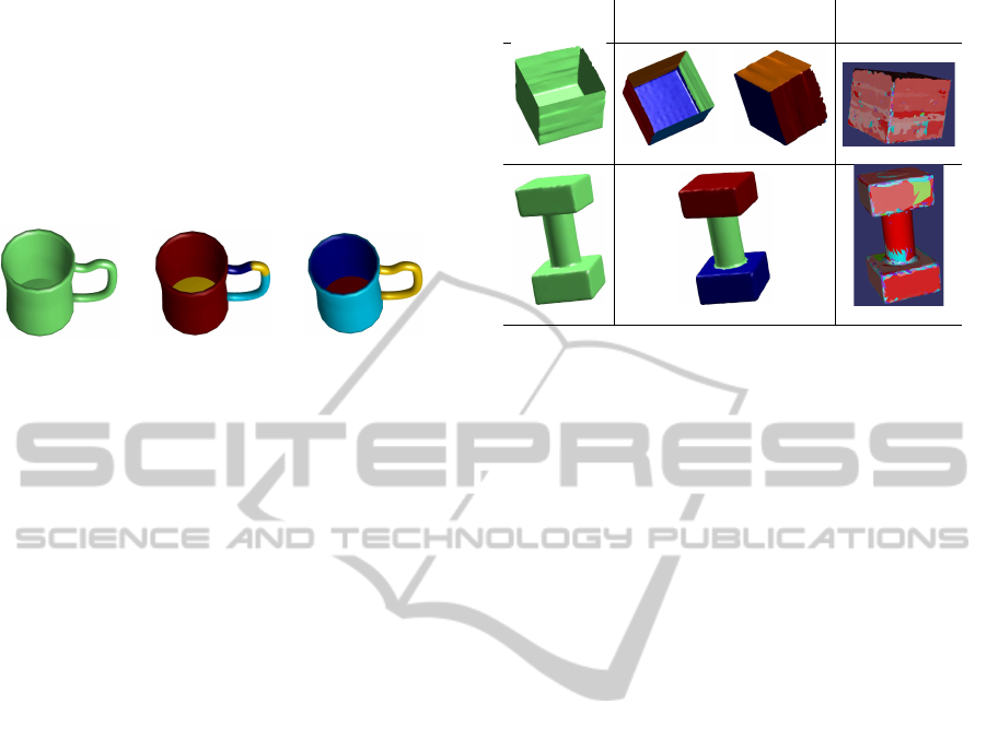
Figure 3b presents the result of applying 3D-
NCuts on a 3D model in order to segment the model
into four clusters. It is observed that the result is
not meaningful, especially on the handle of the mug;
to circumvent this problem, we apply an exponential
function on the weights of similarity to make small
weight values even smaller and large values larger.
This modification separates regions very well but, in
order to assign a priority to the neighbours in com-
parison with the points that are far from each other, a
small value η is added to the weights of neighbouring
vertices. This parameter (η) forces the algorithm to
always consider neighboring surfaces to be candidate
for merger. Therefore the similarity matrix is rede-
fined as
w(i, j) =
e
α cos≺(~n
i
,~n
j
)
+ η if i and j are connected by an edge
0 otherwise
(6)
Figure 2: A color-coded representation of the similarity ma-
trix values for two 3D models, where, blue indicates the
lowest value and red indicates the largest value.
3D-NCuts:AdaptingNormalizedCutsto3DTriangulatedSurfaceSegmentation
147
As represented in Figure 3c, the modified sim-
ilarity matrix renders the segmentation meaningful.
When a human wishes to segment this 3D model into
four segments it separates it into the handle, the bot-
tom, the inner part of the mug and the outer part of the
mug. This is precisely what the 3D-NCuts algorithm
does to achieve the mug model. Henceforth, Equation
6 is used in the first step of Algorithm 1 and results in
a better segmentation for all other 3D models.
(a)
(b)
(c)
Figure 3: (a) 3D model, (b) result of 3D-NCuts segmenta-
tion with k = 4 and using the similarity matrix presented in
step 1 of Algorithm 1. (c) result of 3D-NCuts segmentation
with the modified weight Equation 6, with k = 4, α = 15,
η = 0.5 (after replacing the similarity equation in step 1 of
Algorithm 1 by Equation 6).
The experimental results of 3D segmentation are
presented in the next section, which shows the good
performance of our approach.
4 EXPERIMENTAL RESULTS
We tested the performance of our approach on various
3D shapes, for different conditions and in compari-
son with other methods. We evaluated this method
on objects we scanned with a handheld scanner (i.e.,
Creaform Go!SCAN handheld 3D scanner) as well as
on 3D models with artificial noise.
The free-form 3D models that are used in the
experiments and the results of segmentation by the
approaches presented in Figure 5 are taken from
the Princeton Shape Benchmark for 3D Segmenta-
tion (Chen et al., 2009). The 3D CAD models
are taken from the database of Purdue University
(ESB) (Jayanti et al., 2006).
The values of similarities between vertices (Equa-
tion 5) are between −1 and 1. For parameter α in
e
αw(i, j)
, choosing a too small value does not create
a large difference between weights on the bound-
aries and the ones on the surface. Choosing a large
value also weakens some useful weights near the high
weights. Since we desire to have a large difference
between the weights on the surface and those on the
boundaries, in all experiments, α is set to an inter-
mediary value of α = 15. The value of η specifies
the impact of neighbour vertices which is set to 0.5 to
keep both dependency and independency of a vertex
to the neighbouring vertices.
(a)
(b)
(c)
3D Model
3D-NCuts
(Xiao et al.,
2011)’s method
k = 5
k = 3
Figure 4: The result of our 3D segmentation approach in
comparison with the method proposed by (Xiao et al., 2011)
on real scanned data. 3D models are presented in column
(a); column (b) and (c) show the result of segmentation by
3D-NCuts and the method presented in (Xiao et al., 2011),
respectively.
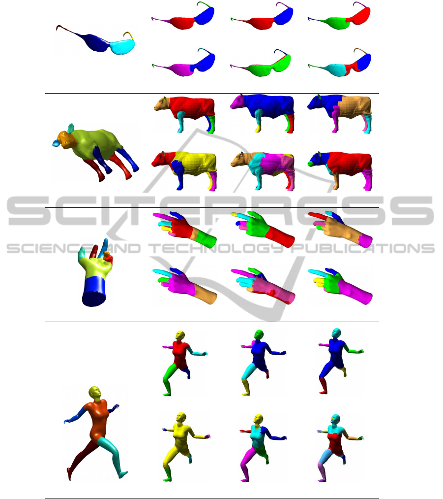
Figure 5 shows the segmentation results using our
method in comparison with some recent approaches.
In this figure, we presented the segmentation re-
sults for four different 3D models. In each row,
column (a) shows the result of our 3D-NCuts seg-
mentation, column (b) presents manual segmentation
which is the ground truth of presented 3D models.
Columns (c), (d), (e), (f), and (g) represent the seg-
mentation results using Randomized Cuts (Golovin-
skiy and Funkhouser, 2008), Normalized Cuts pre-
sented in (Golovinskiy and Funkhouser, 2008), Ran-
dom walk (Lai et al., 2008), fitting primitive (At-
tene et al., 2006) and shape diameter (Shapira et al.,
2008) approaches, respectively. The results show that
in comparison to other methods, our segmentation
approach is able to provide a 3D segmented model
which more clearly resembles the ground truth.
Figure6 shows some results of our method for
CAD models in comparison with a recently pre-
sented CAD model segmentation method (Xiao et al.,
2011). This approach segments the model automati-
cally without considering the number of clusters. The
results of the method proposed by (Xiao et al., 2011)
in Figure 6, are obtained from their prepared GUI.
Since their method is based on Hough transform and
Gauss sphere mapping to detect planes and cylinders,
it can detect these primitives very well but it some-
times fails to associate the parts together (such as the
red line, in Figure6, in the last column of the first row,
on cylinder at the bottom part of the object which is
detected as the top cylinder).
As shown in Figure 6, our method can segment
a 3D CAD model very well. The segmentation re-
sults are presented with different number of clusters
GRAPP2014-InternationalConferenceonComputerGraphicsTheoryandApplications
148
(b) (c) (d)
k = 4 k = 4 k = 4
(a) (e) (f) (g)
k = 4 k = 4 k = 4 k = 8
(b) (c) (d)
k = 8 k = 8 k = 8
(a) (e) (f) (g)
k = 8 k = 8 k = 8 k = 9
(b) (c) (d)
k = 8 k = 8 k = 8
(a) (e) (f) (g)
k = 8 k = 8 k = 8 k = 7
(b) (c) (d)
k = 6 k = 6 k = 6
(a) (e) (f) (g)
k = 6 k = 6 k = 6 k = 16
Figure 5: Comparison to previous segmentation methods. The methods that are compared (a) Our method, (b) Manual
segmentation, (c) Randomized Cuts (Golovinskiy and Funkhouser, 2008), (d) Normalized Cuts presented in (Golovinskiy and
Funkhouser, 2008), (e) Random Walk (Lai et al., 2008), (f) Fittingprimitives (Attene et al., 2006), (g) Shape Diameter (Shapira
et al., 2008). The last method, Shape Diameter (Shapira et al., 2008), is an automatic algorithm which determines the numbers
of clusters.
to show the effectiveness of our method in detecting
more geometric primitives. In the first row, where the
object was segmented into three clusters, our method
separated the cylinder from the cube-like shape: the
planes of the cube which are located in the same di-
rection as those of the cylinder have been included
with the cylinder, separating them from the remain-
der of the cube-like shape. In the case of k = 8, it
3D-NCuts:AdaptingNormalizedCutsto3DTriangulatedSurfaceSegmentation
149
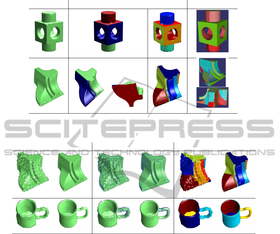
(a) (b) (c)
3D Model
3D-NCuts (Xiao et al., 2011)’s method
k = 3 k = 8
k = 3 k = 8
Figure 6: The result of our 3D segmentation method in comparison with the method proposed by (Xiao et al., 2011). Column
(a) shows the 3D models, column (b) and (c) present the result of segmentation by 3D-NCuts and the method proposed
by (Xiao et al., 2011), respectively. In the first row, column (b) shows results for different numbers of clusters.
(a) (b) (c)
3D Noisy/Noiseless Model
Normals of the model 3D-NCuts
k = 8
k = 4
Figure 7: The result of our 3D segmentation approaches in the presence of noise. Column (a) shows the 3D noisy or noiseless
models. The normals of models presented in column (a) are shown in column (b). Column (c) is representing the results of
segmentation by 3D-NCuts for both noisy and noiseless models.
also detects the cylinder, planes and four sides of the
cube-like shape. In the second row, the results of
segmenting the “fandisk” model into three and eight
clusters, show that our method achieves better results
than the method presented in (Xiao et al., 2011). With
an increasing number of clusters our approach detects
more different geometric primitives as well.
In Figure4, we present the segmentationresults for
real 3D data. We scanned two real objects in our lab
to evaluate the efficiency of our method on real data.
The models were scanned with an accuracy of 2 mm
with the Go!SCAN scanner. As observed, our method
segments the real CAD models much better than the
approach presented in (Xiao et al., 2011) for CAD
models. This illustrates that the method presented
in (Xiao et al., 2011) is not robust in the presence of
noise, even at low levels.
To further demonstrate the robustness of our algo-
rithm in the presence of noise, we added some Gaus-
sian noise to both free-form and CAD mesh models
and applied our approach to segment these shapes.
These models, with this small amount of vertices, are
sensitive even in the presence of small noise levels.
Figure 7 shows the segmentation results in the case
of noiseless and noisy models. Column (c) of Figure
7 shows the segmentation results obtained using 3D-
NCuts. Considering noisy and pure models, the re-
sults of segmenting a 3D model are almost the same
with or without noise. For the mug model shown in
second column, the 3D-NCuts algorithm segments the
noisy mug into virtually the same four clusters as is
the case for the noiseless mug. These results indicate
that our approach is relatively stable, even in the pres-
ence of noise.
GRAPP2014-InternationalConferenceonComputerGraphicsTheoryandApplications
150
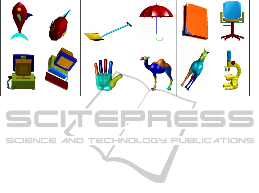
k = 8 k = 4 k = 3 k = 6 k = 8
k = 15 k = 6 k = 26 k = 10 k = 15
Figure 8: More results on our 3D segmentation approach.
To further illustrate the effectiveness of our ap-
proach more results of segmentation are presented
in Figure 8. As can be observed, our methods are
applicable for both 3D free-form and CAD models.
For example, for the horse model with 10 clusters,
3D-NCuts segments the shape into four different seg-
ments of legs, two segments of ears and one segment
for each of the following: tail, eyes, face and body.
Different meaningful geometric features of the other
models in this figure are obtained as well.
5 CONCLUSIONS
In this paper, we presented a spectral-based 3D seg-
mentation method. This method, 3D-NCuts, identi-
fies the Laplacian matrix of the 3D data and attempts
to solve the segmentation problem based on the idea
of 2D Normalized Cuts. The most important part of
this method is the definition of the similarity matrix.
Here, we defined this matrix based on normals of ver-
tices and applied an exponential function with consid-
ering some constants to discriminate different geome-
tries from each other in an object. The results show
the efficiency of this approach for both free-form and
CAD 3D models in comparison with other methods.
The results are very similar to manual segmentation
(the ground truth) which reveals our approach is able
to produce meaningful segmentation. From the re-
sults, our method works better or at least similarly to
other presented methods. We also tested our approach
on real scanned data with good results. Even in the
presence of significant noise, our approach was able
to produce significant segmentation.
ACKNOWLEDGEMENTS
This work was supported by the NSERC-Creaform
Industrial Research Chair on 3D Sensing. Z. Toony
was supported by a FRQ-NT post-graduate scholar-
ship. The authors thank Hongwei Lin for providing
us with the GUI of their method (Xiao et al., 2011).
REFERENCES
Agathos, A., Pratikakis, I., Perantonis, S., Sapidis, N., and
Azariadis, P. (2007). 3D mesh segmentation method-
ologies for CAD applications. Computer-Aided De-
sign and Applications, 4(6):827–841.
Attene, M., Falcidieno, B., and Spagnuolo, M. (2006). Hi-
erarchical mesh segmentation based on fitting primi-
tives. The Visual Computer, 22(3):181–193.
Benhabiles, H., Lavou´e, G., Vandeborre, J.-P., and Daoudi,
M. (2011). Learning boundary edges for 3D-Mesh
segmentation. In Computer Graphics Forum, vol-
ume 30, pages 2170–2182. Wiley Online Library.
Benhabiles, H., Lavou´e, G., Vandeborre, J.-P., Daoudi, M.,
et al. (2012). Kinematic skeleton extraction based on
motion boundaries for 3D dynamic meshes. In Eu-
rographics 2012 Workshop on 3D Object Retrieval,
pages 71–76.
Benhabiles, H., Vandeborre, J.-P., Lavou´e, G., and Daoudi,
M. (2009). A framework for the objective evaluation
of segmentation algorithms using a ground-truth of
human segmented 3D-models. In IEEE International
Conf. on Shape Modeling and Applications (SMI),
pages 36–43.
Blais, F. (2004). Review of 20 years of range sensor devel-
opment. volume 13, pages 231–243. Journal of Elec-
tronic Imaging.
Carnero, J., Molina-Abril, H., and Real, P. (2012). Tri-
angle mesh compression and homological spanning
3D-NCuts:AdaptingNormalizedCutsto3DTriangulatedSurfaceSegmentation
151

forests. In Proceedings of the 4th international conf.
on Computational Topology in Image Context, pages
108–116.
Chen, X., Golovinskiy, A., and Funkhouser, T. (2009). A
benchmark for 3D mesh segmentation. ACM Trans-
actions on Graphics (TOG), 28(3):73.
Chung, F. R. (1997). Spectral graph theory. CBMS Regional
Conference Series in Mathematics, 92.
Fowlkes, C., Belongie, S., Chung, F., and Malik, J. (2004).
Spectral grouping using the Nystrom method. IEEE
Transactions on Pattern Analysis and Machine Intel-
ligence, 26(2):214–225.
Golovinskiy, A. and Funkhouser, T. (2008). Randomized
cuts for 3D mesh analysis. In ACM Transactions on
Graphics (TOG), volume 27, page 145.
Huber, D., Kapuria, A., Donamukkala, R., and Hebert, M.
(2004). Parts-based 3D object classification. In Com-
puter Vision and Pattern Recognition (CVPR), vol-
ume 2, pages 82–89.
Jayanti, S., Kalyanaraman, Y., Iyer, N., and Ramani, K.
(2006). Developing an engineering shape bench-
mark for CAD models. Computer-Aided Design,
38(9):939–953.
Jiang, W., Tian, J., Cai, K., Zhang, F., and Luo, T.
(2012). Tangent-plane-continuity maximization based
3D point compression. In 19th IEEE International
Conf. on Image Processing (ICIP), pages 1277–1280.
Kalogerakis, E., Hertzmann, A., and Singh, K. (2010).
Learning 3D mesh segmentation and labeling. ACM
Transactions on Graphics (TOG), 29(4):102.
Karim Baareh, A., Sheta, A. F., and Al-Batah, M. S. (2012).
Feature based 3D object recognition using artificial
neural networks. International Journal of Computer
Applications, 44(5):1–7.
Katz, S. and Tal, A. (2003). Hierarchical mesh decomposi-
tion using fuzzy clustering and cuts, volume 22. ACM
Trans. on Graphics.
Lai, Y.-K., Hu, S.-M., Martin, R. R., and Rosin, P. L. (2008).
Fast mesh segmentation using random walks. In Pro-
ceedings of the ACM symposium on Solid and physical
modeling, pages 183–191.
Lavou´e, G., Vandeborre, J.-P., Benhabiles, H., Daoudi,
M., Huebner, K., Mortara, M., Spagnuolo, M., et al.
(2012). SHREC’12 Track: 3D mesh segmentation. In
Eurographics 2012 Workshop on 3D Object Retrieval,
pages 93–99.
Liu, R. and Zhang, H. (2004). Segmentation of 3D meshes
through spectral clustering. In Proceedings. 12th Pa-
cific Conf. on Computer Graphics and Applications,
pages 298–305.
Liu, R. and Zhang, H. (2007). Mesh segmentation via spec-
tral embedding and contour analysis. In Computer
Graphics Forum, volume 26, pages 385–394. Wiley
Online Library.
Murase, H. and Nayar, S. K. (1995). Visual learning and
recognition of 3-D objects from appearance. Interna-
tional journal of computer vision, 14(1):5–24.
Ning, X., Li, E., Zhang, X., and Wang, Y. (2010). Shape
decomposition and understanding of point cloud ob-
jects based on perceptual information. In Proceed-
ings of the 9th ACM SIGGRAPH Conf. on Virtual-
Reality Continuum and its Applications in Industry,
pages 199–206.
Sam, V., Kawata, H., and Kanai, T. (2012). A ro-
bust and centered curve skeleton extraction from 3D
point cloud. Computer-Aided Design & Applications,
9(6):869–879.
Selinger, A. and Nelson, R. C. (1999). A perceptual group-
ing hierarchy for appearance-based 3D object recog-
nition. Computer Vision and Image Understanding,
76(1):83–92.
Shamir, A. (2008). A survey on mesh segmentation tech-
niques. In Computer graphics forum, volume 27,
pages 1539–1556. Wiley Online Library.
Shapira, L., Shamir, A., and Cohen-Or, D. (2008). Con-
sistent mesh partitioning and skeletonisation using
the shape diameter function. The Visual Computer,
24(4):249–259.
Shi, J. and Malik, J. (2000). Normalized cuts and image
segmentation. IEEE Transactions on Pattern Analysis
and Machine Intelligence, 22(8):888–905.
Shlafman, S., Tal, A., and Katz, S. (2002). Metamorpho-
sis of polyhedral surfaces using decomposition. In
Computer Graphics Forum, volume 21, pages 219–
228. Wiley Online Library.
Xiao, D., Lin, H., Xian, C., and Gao, S. (2011). CAD
mesh model segmentation by clustering. Computers
& Graphics, 35(3):685–691.
Yu, H., Chen, J., Wan, W., Wang, R., and Yu, X. (2012). A
segmentation progressive mesh compression method.
In International Conf. on Audio, Language and Image
Processing (ICALIP), pages 1163–1166.
Zhang, H. and Liu, R. (2005). Mesh segmentation via re-
cursive and visually salient spectral cuts. In Proc. of
vision, modeling, and visualization, pages 429–436.
Zhang, Q., Song, X., Shao, X., Shibasaki, R., and Zhao, H.
(2012). Unsupervised skeleton extraction and motion
capture from 3D point cloud sequences. Neurocom-
puting, 100.
Zhang, Y., Paik, J., Koschan, A., Abidi, M. A., and Gor-
sich, D. (2002). Simple and efficient algorithm for
part decomposition of 3-D triangulated models based
on curvature analysis. In International Conference on
Image Processing, volume 3, pages III–273.
GRAPP2014-InternationalConferenceonComputerGraphicsTheoryandApplications
152
