
Shader-based Automatic Camera Layout Optimization for Mobile
Robots using Genetic Algorithm
Shuiying Wang and Ra
´
ul Rojas
Institute of Applied Computer Science, Freie Universit
¨
at Berlin, Arnimallee 7,D-14195, Berlin, Germany
Keywords:
Shader, Camera Layout Optimization, Mobile Robot, Genetic Algorithm.
Abstract:
Given a mobile robot and a certain number of cameras, this paper addresses the problem of finding locations
and orientations of the cameras relative to the robot such that an optimality criteria is maximized. The optimal-
ity criteria designed in this paper emphasizes the trade-off between the coverage of area of interest around the
robot by the cameras subject to occlusion constraints and the proximity of cameras to the robot structure. Real
coded genetic algorithm is employed to search for such optimal layout and the optimality criteria serves as the
fitness function. The computation intensive parts, namely the coverage and proximity analysis, are adapted
to such a form that GPU with programmable shader can be accommodated to accelerate them. A graphical
user interface tool is constructed to allow observation and checks during the optimization process. Promising
results are displayed in an experiment concerning a truck with seven cameras. The optimization framework
outlined in this paper can also be extended to optimize layout of scanning sensors like LiDAR and Radar
mounted on arbitrary structures.
1 INTRODUCTION
Mobile robots often use cameras to perceive their sur-
roundings, as is shown in the case of autonomous
vehicles with a vision system consisting of cameras,
LiDARs and Radars. As camera sensors become
more affordable and effective, an increasing number
of daily driven cars and utility vehicles are adopting
camera systems to improve driving safety. For in-
stance, a garbage truck operator needs a vision sys-
tem to secure loading and unloading of the garbage at
the rear of the truck. Another example comes from
the field of mining truck. Huge mining trucks up to
date can be 10 meters tall and 20 meters long; as a
result, it is necessary for them to have a monitoring
system in order to avoid accidents with other small
vehicles. These mobile vehicles with such vision as-
sistants are also categorized as mobile robots in terms
of the problem domain concerned in this paper.
Efficiency and effectiveness are crucial in such
camera systems: the limited power supply and
space resources on mobile robots restrict the camera
amount, while desirable effects of image processing
algorithms demand extensive and detailed perception.
Therefore, an optimal layout of cameras is signifi-
cantly important. However there has been little re-
search effort towards this problem in field of mobile
robots so far. The work presented in this paper is thus
motivated to fill this gap, i.e. to address the problem
of camera layout optimization for mobile robots.
Without loss of generality, given a mobile robot R,
certain area of interest A around R, a fixed number N
of cameras C and a bounded continuous design space
P from which the locations and orientations of cam-
eras are chosen; we are focusing on finding a set of
camera parameters P
optimal
that can maximize an ob-
jective function F
N
implying the trade-off between the
coverage of the camera system over A and the prox-
imity of cameras to the robot structure. Equation (1)
gives a mathematical expression of the problem. In
terms of evaluation of a certain layout, coverage cal-
culation and the computation of proximity of cameras
to the robot structure are two key issues among oth-
ers. We adapt the coverage analysis and proximity
computation to such a form that GPU with shader can
be adopted to enhance the computation. Genetic al-
gorithm (GA) is employed as optimization method.
Our solution framework can also be applied to hy-
brid sensor system consisting of cameras, LiDARs
and Radars.
P
optimal
= argmax
P
0
∈P
F
N
(P
0
, R, A) (1)
With problem definition stated above, main con-
tributions of our work are as follows:
153
Wang S. and Rojas R..
Shader-based Automatic Camera Layout Optimization for Mobile Robots using Genetic Algorithm.
DOI: 10.5220/0004692201530160
In Proceedings of the 9th International Conference on Computer Graphics Theory and Applications (GRAPP-2014), pages 153-160
ISBN: 978-989-758-002-4
Copyright
c
2014 SCITEPRESS (Science and Technology Publications, Lda.)

(1) First attempt to take into account in camera
layout optimization the proximity of the cameras to
the structure on which they are mounted and to trans-
form the problem in a way that shader can be em-
ployed to enhance the optimization process.
(2) Detailed presentation of a GUI Tool frame-
work allowing observations and checks in optimiza-
tion process.
(3) First attempt to adopt real coded GA to search
for the optimal layout of a camera system in the
context of mobile robot over a continuous design
space, as opposed to using preselected camera can-
didates with discrete location and orientation values
presented in works in other contexts such as security
monitoring system.
The remaining of this paper is organized as fol-
lows: in Section 2 a review of related work is il-
lustrated and our approach is justified in comparison
with them. In Section 3 the methodology with respect
to coverage and proximity analysis is presented. In
Section 4 the instantiation of the methodology using
shader are described in detail. After that, GA op-
timization overview and implementation details are
presented in Section 5. Section 6 depicts the GUI
Tool. The experiment and related results about cam-
era layout optimization for a truck are presented in
Section 7. Section 8 contains a conclusion of this
work and directions of future work.
2 RELATED WORK
Research in the area of camera layout optimization
has roots in the Art Gallery Problem (AGP), an ex-
tensively studied topic in the field of computational
geometry. The purpose of AGP is to find the posi-
tions of a minimum number of guards such that every
point in a polygon is within sight of at least one guard.
Extensive reviews about AGP and its variants can
be found in (O’Rourke, 1987),(Erdem and Sclaroff,
2006),(Murray et al., 2007). In short, the determi-
nation of exact solution for AGP is NP-hard, while
many efficient algorithms and heuristics are available
to ensure a suboptimal decision; theoretical results
concerning AGP are based on unrealistic assumptions
such as infinite Field Of View (FOV) for cameras and
therefore they cannot provide effective approaches to
real world problems.
Consequently, a large majority of research related
to optimization of camera configuration with more re-
alistic assumptions has emerged and most of it is set in
the context of in- or outdoor surveillance and monitor-
ing system, where video camera systems are widely
employed and an optimal arrangement of cameras is
crucial.
In (David et al., 2007) a sensor placement ap-
proach was proposed for monitoring human activities
in indoor scenes. Their goal is to determine a sub-
set of preselected sensor samples such that the sensor
cost is minimized and the required scene is covered.
Firstly, the polygons in the scene are sampled into a
list of points and the points covered by each sensor
candidate are determined via a ray tracing algorithm
from Matlab. Then branch and bound algorithm and
GA are implemented respectively for an optimal solu-
tion. The approach is exemplified with cameras while
the authors stated that it also applies to other camera-
like sensors.
With the same basic idea as (David et al., 2007),
(Erdem and Sclaroff, 2006) proposed a radial sweep
visibility algorithm to handle holes in the floor dur-
ing ray tracing rendering in order to consider the oc-
clusions caused by them. In terms of optimization
method, it was asserted that the optimality of the final
result would depend on the density of the preselected
camera samples with discrete location and orientation
values.
Although it was stated in (David et al., 2007) and
(Erdem and Sclaroff, 2006) within their methodology
that the problems are set in a 3D context, yet the im-
plementations were carried out in simplified 2D ver-
sions.
A framework was developed in (Murray et al.,
2007) to optimize video sensor placement for secu-
rity monitoring in an urban area. They employed Ge-
ographical Information System (GIS) to implement
visibility analysis(i.e. coverage analysis) and adopted
a commercial optimization software to search for the
optimal solution. They focused on illustrating the ef-
fects of various trade-offs among different areas of in-
terest via implementing the optimization framework.
Research in (Becker et al., 2009) focused on cam-
era layout optimization for detection of human be-
ings. Instead of a planar area of interest, a 3D volume
of interest extruded from horizontal surfaces up to the
height of a human being is taken as the target space.
The 3D volume is sampled into a series of points and
the coverage is computed by a ray tracing algorithm.
A greedy heuristic is followed in the selection of cam-
eras.
An automatic approach is proposed in (Fleishman
et al., 2000) for choosing camera positions that can
guarantee an image-based modeling of high quality.
In addition to the coverage requirements, the rendered
images should be qualified for the 3D scene mod-
elling task. Correspondingly, the coverage quality is
stressed. They mentioned that they employ 3D hard-
ware to speed up the visibility analysis; thus our vis-
GRAPP2014-InternationalConferenceonComputerGraphicsTheoryandApplications
154

ibility analysis method might be similar to theirs in
scope.
A wireless sensor network optimization using
multi-objective GA(MOGA) is described in (Jourdan
and de Weck, 2004). Besides horizontal and verti-
cal coordinates of the sensors, they also introduce the
sensor number into the design vector. The MOGA
provides the end-user with a set of Pareto-optimal lay-
outs illustrating the trade-off between different objec-
tives, one of which is the number of deployed sensors.
To conclude, the methodology and implementa-
tion presented in our work suits very well to the con-
text of mobile robots. Firstly, in contrast to the huge
amount of sensors and quite large area of interest in
contexts of surveillance system mentioned above, the
number of sensors mounted on a robot is very lim-
ited and thus the area of interest of such a camera
system is relatively small. Consequently, a more ac-
curate coverage analysis considering occlusion con-
straints imposed by the robot body itself is necessary
and tractable in terms of time consumption. Secondly,
mobile robots are always in dynamic states due to
motion and suffer from frequent contact with its sur-
roundings, thus it is better to place the sensors close
to the robot body for the sake of compactness. As
a result, the proximity between the cameras and the
robot body should be considered in the evaluation of a
camera layout. Lastly, as the design space of the opti-
mization problem in the case of mobile robot is much
smaller than that of in-or outdoor surveillance sys-
tems, we do not need to preselect sensor candidates;
instead, we use GA to search over a continuous de-
sign space with bounding limits defined by the robot
body structure and the target area, which is otherwise
computationally prohibitive in terms of surveillance
systems involving large areas.
3 METHODOLOGY
The evaluation of a given layout according to the op-
timality criteria that emphasize the trade-off between
coverage and proximity is the most computation in-
tensive part in the problem focused in this paper. We
formulate the coverage and proximity analysis in such
a way that rasterization based rendering technique
can be employed to enhance the computation via the
use of GPU. The programmable shader in the render-
ing pipeline is designed to record the information we
need.
3.1 Coverage Analysis
As the FOV of a camera can be represented as a frus-
tum, the coverage analysis within the scope of this
paper can be formulated in the following way: given
several frustums , a set of primitives like points, lines
and polygons serving as area of interest to be covered
and another set of such primitives imposing occlu-
sions, the problem is to calculate the intersection area
of the frustums and the area of interest subject to the
occlusions. It is almost intractable in terms of com-
putational intensity to obtain accurate results for such
problems when the primitives and the frustums are in
a large amount and positioned irregularly, which is
just the case as presented in this paper. As a result,
the coverage analysis algorithm designed in this pa-
per implies a trade-off between the accuracy and the
time consumption and is based on the parallel com-
putation architecture of GPU and the flexibility of the
programmable shader. The corresponding method is
presented in the following:
(1) The set of primitives composing the area of in-
terest is discretized into small entities, with each as-
signed a specific identity number. All the primitives
producing occlusions are assigned one common iden-
tity number.
(2) While normally the rendering result of the
frustum by GPU is an image of pixels with each con-
taining color information of the targeted entity(i.e, the
entity that lies within FOV of the frustum and is used
to provide information for that specific pixel during
image rasterization), a specific shader can be designed
to record the identity number of the entity rather than
the color information in the pixel.
(3) After all the frustums are rendered, the cover-
age is calculated according to the set of entities be-
longing to the area of interest recorded in the images.
The fact that an entity would appear more than once
means that some part of the covered areas of differ-
ent frustums are overlapped, so in such case only one
instance of the entity should be considered. Weights
can be assigned to the entities to indicate their various
degrees of importance.
3.2 Proximity Analysis
Proximity analysis can be reduced to finding the
shortest euclidean distance between a point and a set
of primitives in 3D space (i.e., the robot in our case).
Such problem is faced with the same challenge as the
coverage analysis. The common method to deal with
it is to make use of a bounding box comprising the set
of primitives and calculate the shortest distance of the
point to the bounding box. As the body structure of a
mobile robot is complicated and irregular, the bound-
ing box solution would result in a large discrepancy
between the real distance and the approximated one.
Shader-basedAutomaticCameraLayoutOptimizationforMobileRobotsusingGeneticAlgorithm
155

The method proposed in this paper can yield a more
accurate proximity calculation with the extra compu-
tation cost incurred being discounted to some extent
by leveraging the parallel computation architecture of
GPU. The resulted method is in principle similar to
that of coverage analysis. The following is applied to
each camera separately:
(1) A certain amount of frustums with origins at
the position of one camera are constructed and ori-
ented in such a way that they can together cover the
3D space around that camera.
(2) The shader for each frustum rendering is de-
signed to record in each pixel the identity number of
the targeted entity as well as its distance to the origin
of the frustum (i.e.,the location of the camera).
(3) The shortest distance (i.e., the proximity) can
be obtained by comparing the distance values saved
in all the pixels with the identity number of the robot
in the images rendered by all the frustums.
Finally, the largest proximity among the member
cameras is assigned to be the proximity of the camera
system. Figure 1 demonstrates the effect of proximity
analysis instantiated with 6 frustums for one camera.
(a) (b) (c) (d)
Figure 1: One camera location with 6 frustums: ψ = 0
◦
, θ =
0
◦
, 90
◦
, 180
◦
, 270
◦
respectively; θ = 0
◦
, ψ = 90
◦
and 270
◦
respectively. φ = 0
◦
for all. (a): 1 frustum; (b): the other 5
frustums; (c): 6 frustums with high resolution images; (d):
6 frustums with low resolution images.
4 INSTANTIATION
In this section, the implementation details with re-
gard to the methodology presented in Section 3 are
described. As the coverage and proximity analysis
are similar in principle with main differences lying in
the information recorded in shader, we only empha-
size the coverage analysis here. The instantiation is
set in the scenario of camera system layout optimiza-
tion for a truck. As is pointed out earlier, a truck with
a camera system is also regarded as a mobile robot
within the scope of this paper.
4.1 Mobile Robot Modelling
The mobile robot model is a 3D mesh composed of
geometric primitives like points, lines and polygons.
It has two roles in the scenario: cameras accommo-
dation and camera view occlusion. In terms of ge-
netic algorithm implementation, we specify a bound-
ing box on the robot as the location design space for
the cameras. With regard to coverage and proxim-
ity analysis, we assign an identity number IDR to the
robot as a common property for all its vertices such
that it can be differentiated from the area of interest.
4.2 Area of Interest Modelling
As surroundings of the mobile robot always change,
it is hard to define a universal target space. As a re-
sult, we specify a planar area around the robot as the
area of interest. While this is a a naive assumption,
it can be adapted to more complex versions as long
as more detailed information about the environment
is available.
The planar area is discretized into a grid to fa-
cilitate coverage calculation and thus the calculation
accuracy depends in part on the resolution of the
grid. Two arrays, WeightArray(WA) of float type
and OccupancyArray(OA) of binary type with each
of size ArraySize(AS), are allocated in shared mem-
ory to store weights and states of coverage of the grid
cells respectively. Each grid cell is assigned a specific
identity number IndexID identical to its index in the
arrays to communicate if any cell is covered by any
camera FOV. It should be noted that the robot identity
number IDR must be outside the scope of the array
index and that the weights are determined according
to specific requirements from the area of interest. The
element in OA is set to the value of 1 if the grid cell
related to it is covered; thus the coverage can be rep-
resented in the form of (2). R and A are implicitly
included in (2) because they have influences on the
values of WA(i) and OA(i).
C
N
(P, R, A) =
AS−1
∑
i=0
(WA(i) × OA(i))
AS−1
∑
i=0
(WA(i))
(2)
In combination with the proximity, the objective
function F
N
in (1) can be formulated as (3), where the
value of α implies the trade-off between coverage and
proximity. The range of the fitness function is [0, 1].
F
N
(P, R, A) = C
N
×
C
N
αProximity
N
+C
N
(3)
GRAPP2014-InternationalConferenceonComputerGraphicsTheoryandApplications
156

4.3 Camera Modelling
The camera, namely the frustum, is modelled by
the camera node specified in OpenSceneGraph(OSG).
More details can be found in (Wang et al., 2012),
where the simulated Radar works in a similar way
to the frustums for coverage analysis while the main
function of simulated LiDAR corresponds to the role
of frustums for proximity analysis. Cameras have
intrinsic and extrinsic properties. The intrinsic ones
concerned in this paper include mainly depth of field
bounded by Near and Far values, vertical FOV, hor-
izontal FOV, vertical resolution and horizontal res-
olution; the first three define the frustum which in
turn determines the transformation matrix from cam-
era coordinates to the 2D image arrangement, while
the last two specify the image resolution. The ex-
trinsic ones contain location (x, y, z) and orientation
(yaw(ψ), pitch(θ), roll(φ)) which specify the trans-
formation matrix from world coordinates to the cam-
era coordinates. In our work only the extrinsic param-
eters are taken as design variables while the intrinsic
ones embodying the camera type remain unchanged
during the optimization.
As we evaluate the coordinated performance of
all the cameras in the camera system, we construct
a class MultiCameraModel comprising both intrin-
sic and extrinsic properties necessary in the mod-
elling of one set of N cameras. The counterpart
of MultiCameraModel with respect to GA is an-
other class MulticameraIndividual involving only
the extrinsic properties. There is only one instance
of MultiCameraModel in shared memory, whereas
the number of MulticameraIndividual instances re-
main consistent with the population size specified for
GA optimization. During the coverage analysis, a
MulticameraIndividual would substitute for extrin-
sic properties of the MultiCameraModel such that the
camera system would be remodelled and the corre-
sponding coverage would be calculated. In addition,
three variables, AllImageProcessed, TotalImages
and ProcessedImages, are allocated in shared mem-
ory to assist the coverage analysis; TotalImages is of
value N while ProcessedImages changes in value on
the fly. The coverage analysis framework is elabo-
rated in subsection 4.4.
A vertex shader and a fragment shader serve in
the rendering pipeline of the camera model such that
the identity number of the objects within the camera
view can be recorded during the rendering stage and
analysed thereafter. Related shader programming is
illustrated in Figure 2. The targeted position of each
pixel is also recorded for displaying of the vision sys-
tem effect. As each of the four elements composing
one fragment ranges from 0 to 1, the identity number
and position must be divided by certain ScaleFactors
before assigned to the FragData(pixel). More details
about shader application in camera-like sensor mod-
elling are available in (Wang et al., 2012).
A class PostRenderingAnalysis is attached to the
camera model for image analysis implemented for
each camera during coverage analysis. The pseudo
code of this procedure is shown in Algorithm.1, where
the letter M indicates the index of the element that
stores IndexID of targeted entity in FragData.
Encode x,y,z, objectID in FragData with
each divided by a proper scale factor
Fragment
shader
Record pos(x,y,z) in eye space
vertex
shader
pos(x,y,z)
objectID
out
in
Uniform
out
Figure 2: Vertex and fragment shader programming.
Algorithm 1: Image analysis for one camera.
1: function POSTRENDERINGANALYSIS( )
2: if !AllImageProcessed then
3: for Frag ← all frags in current image do
4: Ob jectID ← Frag[M] × ScaleFactor
5: if 0 ≤ Ob jectID < ArraySize then
6: OccupancyArray[Ob jectID] ← 1
7: end if
8: end for
9: ProcessedImages ← ProcessedImages +
1
10: if ProcessedImages == TotalImages
then
11: AllImageProcessed ← true
12: end if
13: end if
14: end function
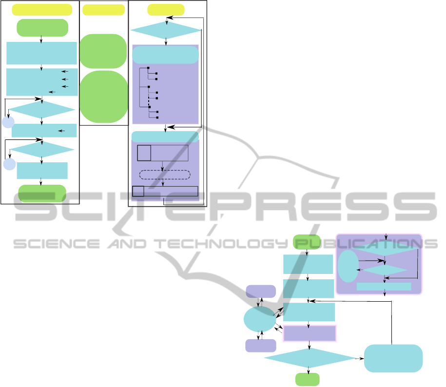
4.4 Coverage Analysis
Coverage analysis serves as part of fitness evaluation
in GA. There are three modules involved in coverage
analysis: GA, shared memory and simulator (camera
modelling and rendering). GA and simulator commu-
nicate with each other via shared memory. Basically,
individuals of GA iteratively substitute for the extrin-
sic parameters of the MultiCameraModel, leading to
reconstructions of the camera models. After images
in the frame buffer are refreshed and analysed, GA
summarizes the fitness value in terms of coverage ac-
cording to (2). Figure 3 displays a detailed implemen-
tation.
Shader-basedAutomaticCameraLayoutOptimizationforMobileRobotsusingGeneticAlgorithm
157
Input: each individual
in one generation
Assign MultiCameraIndividual
(extrinsic parameters)
to MultiCameraModel
MultiCameraChanged
true
ProcessedImages
0
AllImagesProcessed
true
MultiCameraChanged ?
false
true
AllImagesProcessed
false
AllImagesProcessed ?
true
false
Calculate fitness
based on Equation (2)
Output: fitness of
this individual
Shared Memory
MultiCameraModel
(extrinsic & intrinsic
parameters of
N cameras)
MultiCameraChanged
ProcessedImages
AllImagesProcessed
Camera system reconstruction
Camera1
CameraN
Area of interest
Robot
Camera2
MultiCameraChanged ?
false
true
Camera system rendering:
Vertex shder
Fragment shder
Image data
Frame buffer
PostRenderingAnalysis
GPU
CPU
OccupancyArray
Array of 0
wait
wait
Visibility analysis in GA
OccupancyArray
Area of interest
Robot
Area of interest
Robot
Simulator
MultiCameraChanged = false
TotalImages = N
Figure 3: Coverage analysis implementation.
5 GENETIC ALGORITHM
IMPLEMENTATION
5.1 Justification for Applying GA
The main characteristics of the optimization problem
defined in this work are as follows:
• It is hard to present the objective in terms of the
design variables: expression of the intersection of
the ground with one single frustum in terms of
design parameters is already very difficult, not to
mention the case where the overlapping area of
every two intersections and the occlusions of the
mobile robot are considered.
• The quantitative and qualitative relationship be-
tween each design variable and the objective is
also difficult to determine. Due to the two reasons
mentioned above, classical slope based optimiza-
tion algorithm is not applicable for our task.
• The design space is continuous and multi-
dimensional. As the time complexity grows expo-
nentially with the number of design parameters,
it would be computationally intractable to simply
discretize the design space and perform a brute
force algorithm.
As a result, GA, an efficient tool in handling op-
timization problems involving functions intractable
by classical optimization methods(Sharapov and Lap-
shin, 2006), is chosen for resolving our problem.
5.2 Optimization Framework
GA imitates natural selection process in search of a
better solution (Holland, 1992). Therefore its basic
idea is to iteratively reproduce a new generation of
individuals through operating on the old one; these
operations should be designed in such a way that the
new generation in general adapts to the environment
at least as well as, if not better than, the old one. Com-
mon operations are selection, crossover and mutation
(Goldberg, 1989). As operations on the individuals
are probabilistic, GA optimization is also a stochas-
tic process which cannot ensure that a solution can be
found. In (Sharapov and Lapshin, 2006) some proofs
on the convergence of several genetic algorithm vari-
ants in the mean are provided. In general, the proba-
bility of operations and the design of operations them-
selves are crucial in terms of search efficiency and
global optimality of the converged solution. Our GA
optimization framework is shown in Figure 4.
Start
Problem & GA
instantiation
Population
initialization
Fitness evaluation
Termination condition
satisfied?
Yes
End
No
Crossover
Mutation
Selection
New
population
Manual check
Manual
check
Shared
memory
GUI Tool
Simulator
Manual check
enabled?
Yes
True
No
Wait
for
a
while
False
Go to next?
(Coverage analysis)
Go to next = false
Figure 4: GA optimization flow chart.
5.3 Implementation Details
The following describes the adaptations of GA for
solving the problem defined in this paper.
• Individual: MultiCameraIndividual containing
design variables of N cameras, as mentioned in
Section 4, is represented in the following way:
[x1, y1, z1, ψ1, θ1, φ1, x2, y2, ......, φN] (4)
• Population: The population size is empirically set
to be around 10 times the number of design vari-
ables of the individual. The initial population is
generated by pseudo random number generator.
• Selection: Detailed discussion of selection meth-
ods are available in (Sivaraj and Ravichandran,
2011). Traditional Roulette Wheel selection is
GRAPP2014-InternationalConferenceonComputerGraphicsTheoryandApplications
158
utilized in this work and thus the probability for
each individual to get involved in crossover is pro-
portionate to their fitness. Elitist selection is also
applied to ensure that individual with the highest
fitness is always passed to the next generation.
• Crossover and mutation: One-point and two-point
crossover are undertaken respectively, each with
two crossover strategies: crossover per camera,
crossover per design variable. The results turned
out to be almost the same, though. Mutation is
applied on one stochastically chosen parameter of
each camera of randomly selected individual cam-
era system.
• Random number generator: Pseudo random
number generator proposed in (Matsumoto and
Nishimura, 1998) is adopted in this work. We ob-
serve that random number is crucial to the success
of the optimization.
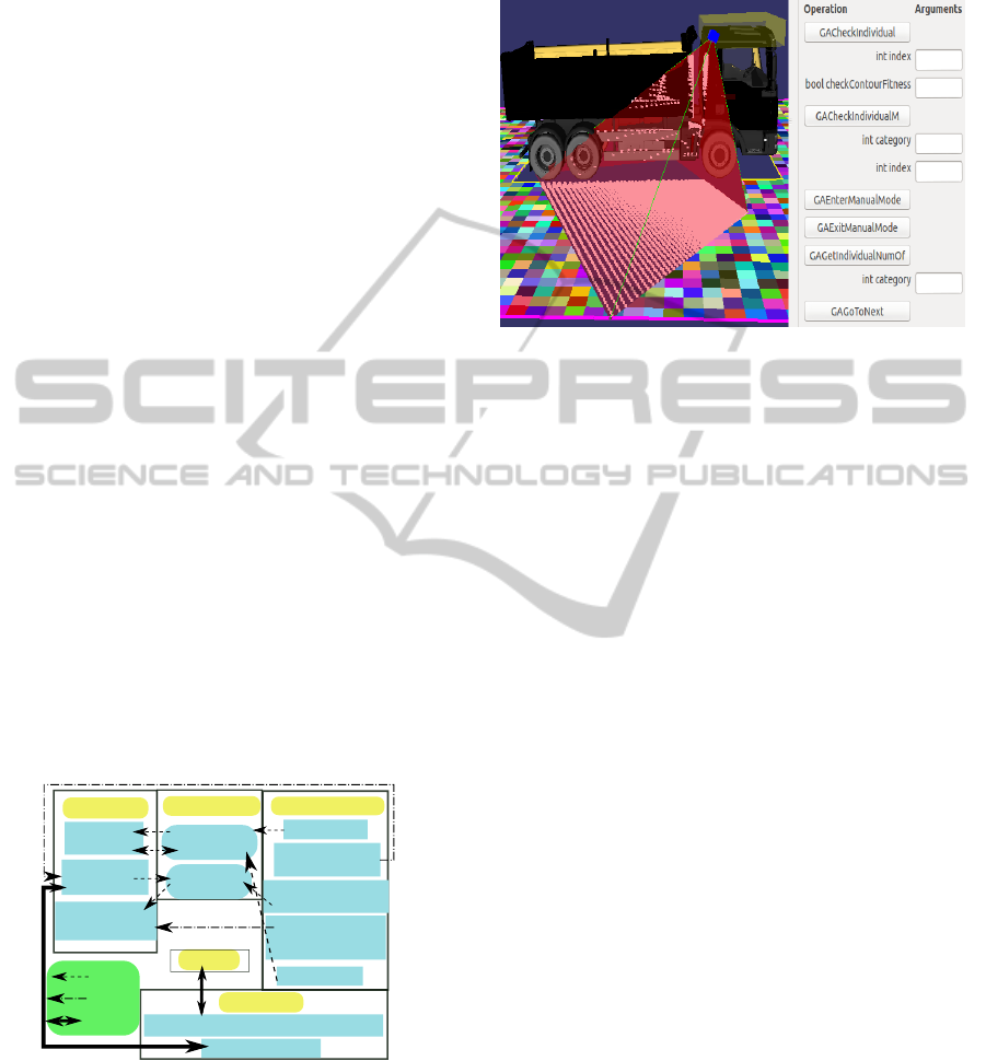
6 GUI TOOL
The GUI Tool contains a display for observation and a
GUI control panel facilitating observation and checks
of the optimization progress and result. The GUI Tool
functionalities and framework is presented in Figure 5
while a snapshot of the GUI Tool is shown in Figure
6. Via the manual check, the GA pauses while the
user can check the performance of any individual in
current generation via GUI Tool. The user can also
modify the individual and GA parameters to influence
the GA process if necessary.
GA Process
Manual
check
Coverage&Proximity
Analysis
Shared Memory
EnableCheck
GoToNext
GUI Control Panel
Enable Check
Check coverage
of an individual
Change
MultiCameraModel
Update Individual
according to
MultiCameraModel
Go to next
MultiCamera-
Model
Update modified
Individual
GUI Display
GA fitness Display
Simulator Display(Individual coverage)
Simulator
Read or Write
Memory
Function
invoke
Inter-Module
communication
Figure 5: GUI Tool functionalities and framework.
7 EXPERIMENT AND RESULTS
In the experiment we consider the problem of a truck
and its vision system of 7 cameras. The scenario is
shown in Figure 6. The experiment is carried out on a
computer with 4 core-Intel i5 CPU and GeForce GT
330 with 1024MB memory.
Figure 6: Problem instantiation and part of GUI Tool.
7.1 Problem Modelling
• Design variable constraints: The yellow bounding
box in Figure 6 suggests the design space of cam-
era locations(indicated by the blue box) while the
orientations are bounded within ψ : [0
◦
, 360
◦
], θ :
[50
◦
, 65
◦
], φ : [0
◦
, 90
◦
]. The red frustum displays
the camera modelling. The white points on the
floor and the truck represent the coverage of cam-
era view and the occlusion effect imposed by the
truck respectively. Image resolution of each cam-
era is 75× 48 for coverage analysis and 180 × 180
for proximity analysis.
• Area of interest: A grid of 2280 cells represents
an area with 5m offset surrounding a truck with
length of 8m and width of 2.5m, as is shown in
Figure 6 with each cell drawn in a random colour.
Weights of all the cells are set equally to 1.
• GA: Population size is 480; crossover rate is 0.99;
mutation rate is 0.1; elitism rate is 1%; it termi-
nates at the 120th iteration.
• Fitness function: refer to (3). We demonstrate two
cases in the following with α equal to 0 and 1 re-
spectively.
7.2 Results
The performance of the camera system after 120 it-
erations is shown in Figure 7 and Figure 8. Figure 9
displays the corresponding evolution processes of 120
iterations in terms of best (green), average (blue) and
worst (red) fitness , and also of proximity (yellow) and
coverage(magenta) for the individual with the best fit-
ness when α is not 0 in the fitness function. It takes
Shader-basedAutomaticCameraLayoutOptimizationforMobileRobotsusingGeneticAlgorithm
159
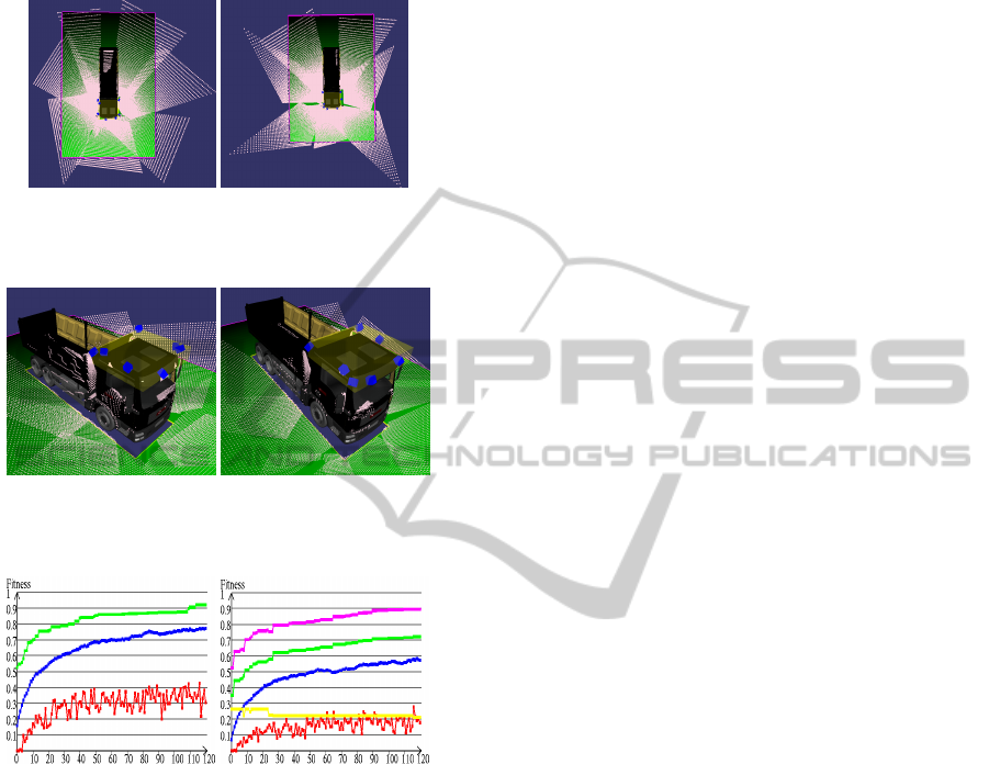
about 80 minutes in average for optimization without
proximity analysis while those with proximity analy-
sis last about 600 minutes.
(a) α = 0 (b) α = 1
Figure 7: Coverage performance of the optimal layouts: (a)
coverage = 0.92, (b) coverage = 0.89.
(a) α = 0 (b) α = 1
Figure 8: Camera locations of the optimal layouts: (a) Prox-
imity = 0.39(m), (b) Proximity = 0.21(m).
(a) α = 0 (b) α = 1
Figure 9: Fitness evolution of 120 iterations.
8 CONCLUSIONS AND FUTURE
WORK
In this paper, we formulate the camera layout opti-
mization problem for a mobile robot and propose an
automatic approach using real coded GA. Coverage
and proximity analysis are accelerated by GPU with
shader. A GUI Tool for observation and checks in
GA process is depicted. The result demonstrated in
the experiment concerning a truck is promising. As
future work, we will focus on following aspects: (1)
modify the fitness function to consider the require-
ments from the image-processing stage, e.g. distance
of neighbouring targeted points on the planar area (2)
investigate into the practical guidelines in choosing
the parameters of genetic algorithm.
REFERENCES
Becker, E., Guerra-Filho, G., and Makedon, F. (2009). Au-
tomatic sensor placement in a 3d volume. In Proceed-
ings of the 2nd International Conference on PErva-
sive Technologies Related to Assistive Environments,
page 36. ACM.
David, P., Idasiak, V., and Kratz, F. (2007). A sensor place-
ment approach for the monitoring of indoor scenes.
Smart Sensing and Context, pages 110–125.
Erdem, U. and Sclaroff, S. (2006). Automated camera lay-
out to satisfy task-specific and floor plan-specific cov-
erage requirements. Computer Vision and Image Un-
derstanding, 103(3):156–169.
Fleishman, S., Cohen-Or, D., and Lischinski, D. (2000).
Automatic camera placement for image-based model-
ing. In Computer Graphics Forum, volume 19, pages
101–110. Wiley Online Library.
Goldberg, D. E. (1989). Genetic algorithms in search, opti-
mization, and machine learning.
Holland, J. H. (1992). Genetic algorithms. Scientific amer-
ican, 267(1):66–72.
Jourdan, D. and de Weck, O. (2004). Multi-objective ge-
netic algorithm for the automated planning of a wire-
less sensor network to monitor a critical facility. In
Proceedings of the SPIE Defense and Security Sym-
posium, volume 5403, pages 565–575.
Matsumoto, M. and Nishimura, T. (1998). Mersenne
twister: a 623-dimensionally equidistributed uniform
pseudo-random number generator. ACM Transactions
on Modeling and Computer Simulation (TOMACS),
8(1):3–30.
Murray, A., Kim, K., Davis, J., Machiraju, R., and Parent,
R. (2007). Coverage optimization to support security
monitoring. Computers, Environment and Urban Sys-
tems, 31(2):133–147.
O’Rourke, J. (1987). Art gallery theorems and algorithms,
volume 57. Oxford University Press Oxford.
Sharapov, R. R. and Lapshin, A. V. (2006). Convergence
of genetic algorithms. Pattern Recognition and Image
Analysis, 16(3):392–397.
Sivaraj, R. and Ravichandran, T. (2011). A review of
selection methods in genetic algorithm. Interna-
tional Journal of Engineering Science and Technol-
ogy, 3(5):3792–3797.
Wang, S., Heinrich, S., Wang, M., and Rojas, R. (2012).
Shader-based sensor simulation for autonomous car
testing. In Intelligent Transportation Systems (ITSC),
2012 15th International IEEE Conference on, pages
224–229. IEEE.
Wright, A. H. et al. (1991). Genetic algorithms for real
parameter optimization. Foundations of genetic algo-
rithms, 1:205–218.
GRAPP2014-InternationalConferenceonComputerGraphicsTheoryandApplications
160
