
Surface Reconstruction of Ancient Water Storage Systems
An Approach for Sparse 3D Sonar Scans and Fused Stereo Images
Erik A. Nelson
1
, Ian T. Dunn
1
, Jeffrey Forrester
1
,
Timothy Gambin
2
, Christopher M. Clark
3
and Zo
¨
e J. Wood
1
1
Computer Science Department, California Polytechnic State University, San Luis Obispo, CA, USA
2
Department of Classics and Archaeology, University of Malta, Msida, Malta
3
Department of Engineering, Harvey Mudd College, Claremont, CA, USA
Keywords:
Geometric Reconstruction, Underwater Stereo Vision, Level Sets.
Abstract:
This work presents a process pipeline that addresses the problem of reconstructing surfaces of underwater
structures from stereo images and sonar scans collected with a micro-ROV on the islands of Malta and Gozo.
Using a limited sensor load, sonar and small GoPro Hero2 cameras, the micro-ROV is able to explore water
systems and gather data. As a preprocess to the reconstruction pipeline, a 3D evidence grid is created by
mosaicing horizontal and vertical sonar scans. A volumetric representation is then constructed using a level
set method. Fine-scale details from the scene are captured in stereo cameras, and are transformed into point
clouds and projected into the volume. A raycasting technique is used to trim the volume in accordance with
the projected point clouds, thus reintroducing fine details to the rough sonar-generated model. The resulting
volume is surfaced, yielding a final mesh which can be viewed and interacted with for archaeological and
educational purposes. Initial results from both steps of the reconstruction pipeline are presented and discussed.
1 INTRODUCTION
Many underwater sites such as cisterns, small sea
caves, and other areas inaccessible to humans offer
extraordinary opportunities for archaeological study.
Remotely Operated Vehicles (ROVs) are commonly
employed to explore such sites due to their small
size, maneuverability, and sensor payload capacity.
A common research goal between archaeologists and
scientists exploring these sites is the ability to cre-
ate accurate reconstructions of the geometry found
within. These reconstructions can be used to visualize
scale, structure, and water level, examine interesting
features more closely, and potentially date the cisterns
and surrounding sites.
In this work we focus on the creation of sur-
face meshes of underwater cisterns and water gal-
leries from a sparsely populated 3D evidence grid
input (Fig. 1). The evidence grid input is created
from a unified map of several horizontal and verti-
cal sonar scans of walls and other geometry, which
are collected with a sonar sensor mounted to a sub-
mersible micro-ROV (McVicker et al., 2012). Previ-
ous work has successfully reconstructed 2D and ex-
truded 2.5D meshes of scanned surfaces using an iter-
ative probabilistic hole filling approach and marching
cubes, using 2D evidence grids from sonar scans as
an input (Forrester et al., 2013). Unfortunately, this
method does not generalize well to sparsely sampled
3D evidence grids, thus inhibiting the reconstruction
of surfaces representative of true site geometry.
The work presented in this paper is motivated by
an ongoing interdisciplinary project with the broad
goal of exploring and mapping cisterns, water gal-
leries, and shoreline caves on the islands of Malta,
Gozo, and Sicily for archaeological study. These wa-
ter storage cisterns, which date back as far as 3000
(a)
(b)
Figure 1: A two-chambered cistern in Mdina, Malta that
was explored and mapped. (a) displays the evidence grid
generated from 40 horizontal sonar scans taken while hover-
ing the ROV up the cistern at 0.2 m intervals. (b) shows the
water tight mesh produced by the first step of our pipeline.
161
A. Nelson E., T. Dunn I., Forrester J., Gambin T., M. Clark C. and Wood Z..
Surface Reconstruction of Ancient Water Storage Systems - An Approach for Sparse 3D Sonar Scans and Fused Stereo Images.
DOI: 10.5220/0004694901610168
In Proceedings of the 9th International Conference on Computer Graphics Theory and Applications (GRAPP-2014), pages 161-168
ISBN: 978-989-758-002-4
Copyright
c
2014 SCITEPRESS (Science and Technology Publications, Lda.)
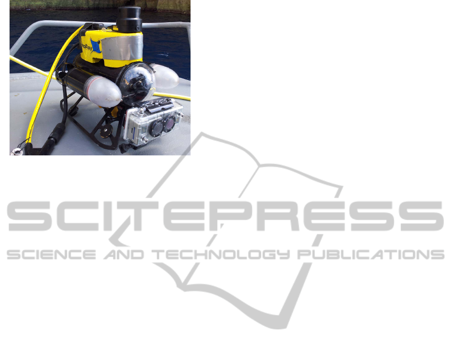
Figure 2: The VideoRay Pro III GTO is an underwater
micro-ROV (36.8 cm x 28.9 cm x 21.6 cm), with a depth
sensor, a compass, and a front and rear video camera. A re-
movable Tritech Micron scanning sonar was mounted to the
top and two vertically aligned GoPro Hero2 cameras were
mounted to the front in a waterproof stereo casing.
B.C.E., were explored with a micro-ROV while col-
lecting sonar scans, depth measurements, compass
measurements, video and stereo images (Fig. 2). Six
different expeditions have resulted in the exploration
of over 100 sites. For more information on evidence
grid generation and the ROV cistern mapping project,
see (McVicker et al., 2012), (Forney et al., 2011),
and (Dobke et al., 2013). Due to the small entry-
ways to these water systems, limited sensors were
used, making data collection challenging and result-
ing in fairly sparse sonar data and poor stereo images
(albeit densely sampled). Our reconstruction pipeline
must handle data with both: varying density and over-
all sparsity.
We use a level set algorithm for surface recon-
struction of sparse 3D sonar data. Unlike other hole
filling algorithms, level set methods are capable of
producing closed surfaces regardless of the sparsity
of the original evidence grid. The level set method
outputs a 3D implicit surface which is used to com-
pute a volume. The reconstructed volume serves as a
good rough approximation of the shape of the site’s
true geometry.
To add finer geometric details, stereo images of
interesting features captured within the cisterns are
turned into point clouds and projected into the vol-
ume. The point cloud data is considerably denser in
the local region it represents compared to the sparse
3D sonar data. To address this difference in density,
the projected stereo point clouds are used as a base
for raycasting, where all voxels in the volume lying
beyond the projected point cloud have their occupan-
cies set greater than zero. After trimming the vol-
ume, the newly introduced zero-crossings allow sur-
facing algorithms such as marching cubes (Lorensen
and Cline, 1987) to reintroduce stereo features previ-
ously omitted from the model. An overview of the
algorithm pipeline is shown in Fig. 3.
Presented in this paper are the details behind ap-
plying the new reconstruction algorithm to 3D sonar
and stereo image data. The proposed algorithm
can produce water tight geometric models, represent-
ing complex underwater storage systems, even given
sparse input data. We present results of three general
surface reconstructions from sparse 3D sonar and one
surface reconstruction with detailed geometry added
via stereo imagery.
2 RELATED WORKS
Surface Reconstruction: Surface reconstruction of
unorganized points in three dimensions is a well stud-
ied problem with many valid methods. One of the
most popular recent approaches is Poisson Surface
Reconstruction (Kazhdan et al., 2006). This method
takes a point cloud with oriented point normals as its
input and creates an indicator function (an inside out-
side table) which it can then use to determine connec-
tivity of input points and extract a 3D model. Other
closely related works include (Mullen et al., 2010)
and work by Deng in (Deng et al., 2011) which use
a variational approach, but either depend on denser
samples or completely closed contours as input.
In contrast, level set methods (Zhao et al., 2001)
take surface patches, curves and points as input and
generate a distance function to input data. Based on
the distance function created, an initial surface sur-
rounding the input data is generated. The initial sur-
face is updated based on vector and scalar fields gen-
erated from the moving surface interface and the input
data. A final surface representative of the initial data
set can be extracted when the initial surface reaches
the input data. Given the sparsity of our input data,
including partial contours and a lack of oriented nor-
mals, level set methods are more appropriate for cre-
ating rough starting models.
Underwater Stereo Reconstruction: The creation
of accurate reconstructions from underwater stereo is
a field of ongoing study. Stereo matching is a dif-
ficult process, complicated further by the underwa-
ter setting where non-uniform illumination, visibility
falloff, and optical aberrations cripple matching algo-
rithms that work well in air. Entire research endeav-
ors have been devoted to characterizing attenuation
and light transmittance through water as a function
GRAPP2014-InternationalConferenceonComputerGraphicsTheoryandApplications
162

Figure 3: The proposed algorithm pipeline to create 3D reconstructions of cisterns.
of sediment levels and object distance for stereo pur-
poses (Nascimento et al., 2009). In (Swirski et al.,
2010), researchers were able to produce accurate dis-
parity maps of underwater scenes using light flicker.
However, there are no such light flicker effects in
the underground cisterns explored in this project with
which to base a stereo correspondence algorithm.
The same budget stereo camera system used in
this project was utilized in (Schmidt and Rzhanov,
2012) to generate disparity maps of underwater
scenes, resolving salient features to ±3 mm. How-
ever, the authors remarked that the cameras were not
ideal due to their short 3.5 cm baseline.
Several research efforts have focused on recon-
struction of underwater scenes from sensor informa-
tion. For example, in (Beall et al., 2010) and (Drap
et al., 2007), areas of the seafloor were reconstructed
through image mosaicing. In (Hurt
´
os et al., 2009),
a sensor fusion approach is used to generate 3D mo-
saics of underwater settings using cameras, sonar, and
other sensors on an AUV. Finally, in (Mahon et al.,
2011), divers collected stereo images of a submerged
town which were used to reconstruct a surface of the
landscape. Campos (Campos et al., 2011) compares
various surface reconstruction methods for sea floor
data and the ARROV project (Papaleo and Puppo,
2004) includes reconstructions from sparse data from
ROVs. While many of these projects provide good
means of reconstructing underwater surfaces, few at-
tempts have been made to model closed 3D man-
made chambers with a micro-ROV and limited sen-
sors without human aid. In addition, few of the avail-
able stereo matching algorithms account for poorly-lit
underwater scenes with no sunlight penetration.
3 SURFACE RECONSTRUCTION
Due to the small entryways to the water systems we
wish to model, only limited sensors can be used, (two
GoPro HD Hero2 cameras and a Tritech SeaSprite
sonar sensor). These limited sensors result in fairly
sparse sonar data and poor stereo images. In order
to construct the best representation of the underwa-
ter system, our reconstruction pipeline must handle
sparse data with varying density.
For our geometric reconstruction we take a 3D ev-
idence grid obtained from a Video Ray Pro III GTO
ROV and Tritech Micron scanning sonar (McVicker
et al., 2012). Unlike previous surface reconstruc-
tion attempts of cisterns which were made from 2D
data (Forrester et al., 2013), this work uses new 3D
sonar data sets. The input 3D evidence grid data
structure is a uniform grid with each cell containing
a probability that the cell represents a solid surface
(i.e. walls, stones, etc.). In order to turn this into a
true point cloud we only accept cells having a proba-
bility greater than a threshold as points in the cloud.
We wish to fit a surface to this input data that best rep-
resents the measured environment. Given the sparsity
of the data, we use a level set method to fit a minimal
surface the input points.
3.1 Level Set Method
Level set surface reconstruction works by starting
with an initial surface that is a bounding volume of
the input data and iteratively moving the surface to-
wards the input data. This surface is represented as Γ,
the zero level set of a function, φ, in 3 dimensions.
In our implementation, we use a gradient flow
model to move the surface, as described in (Zhao
et al., 2001). Our adopted movement equation is:
∆φ = ∆t|~n|d
(P−1)
~g ·~n +
1
P
dκ (1)
where ∆t is a fixed time step, ~n is the gradient of
φ, d is the distance to the nearest original data point,
~g is the gradient of the distance function, and κ is the
curvature of the current surface. ~n, φ, d, ~g, and κ are
all functions of 3 dimensions represented by voxels
in a volume. Eq. 1 is used to iteratively move the
function φ so that its zero level set φ moves towards
the final reconstructed surface.
During each iteration we update the values of φ,~n,
and κ for the voxels in the volume. To increase per-
formance, we only calculate these values for points in
SurfaceReconstructionofAncientWaterStorageSystems-AnApproachforSparse3DSonarScansandFusedStereo
Images
163

the narrow band, as described in (Adalsteinsson and
Sethian, 1994).
We calculate φ to be the distance from each voxel
to Γ. To calculate κ, we use the following equations,
adopted from (Osher and Fedkiw, 2003):
κ =φ
2
x
φ
yy
− 2φ
x
φ
y
φ
xy
+ φ
2
y
φ
xx
+
φ
2
x
φ
zz
− 2φ
x
φ
z
φ
xz
+ φ
2
z
φ
xx
+
φ
2
y
φ
zz
− 2φ
y
φ
z
φ
yz
+ φ
2
z
φ
yy
(2)
Here, φ
x
is the first partial derivative of φ in the
x direction. We use the second-order accurate central
and finite difference formulae given in Eqs. (3)-(5).
φ
x
=
φ
i+1
− φ
i−1
2∆x
(3)
φ
xx
=
φ
i+1
− 2φ
i
+ φ
i−1
∆x
2
(4)
φ
xy
=
φ
i+1
− φ
i−1
2∆x
φ
i+1
− φ
i−1
2∆x
(5)
where φ
y
, φ
z
, φ
yy
, φ
zz
, φ
xz
, and φ
yz
are similarly
calculated.
d must be calculated for all voxels in the volume,
which can be a prohibitively large number of calcula-
tions. To efficiently calculate the distance function we
use the fast marching method described in (Sethian,
2001).
Under ideal circumstances the surface reconstruc-
tion process can be exited once the surface no longer
changes significantly between iterations - at this
point a minimum surface of the input data has been
reached. However, in sparse data sets such as those
we collected from cisterns, the surface may be pulled
through gaps in the data where a surface actually ex-
isted. We therefore allow for human input to end the
surface reconstruction process early when an accept-
able surface has been reached but before that surface
has been pulled too far through holes in the data.
4 STEREO RECONSTRUCTION
While the 3D volumetric reconstructions from Sec. 3
give a broad idea of the true shape of the cistern geom-
etry, the Tritech Micron scanning sonar fails to cap-
ture small features such as crevices, rocky walls, and
archways due to a large 35
◦
vertical beam angle. In
addition, both hardware and software resolution con-
straints are introduced in the scan retrieval and ev-
idence grid generation preprocessing stages. These
limitations cause the volumetric 3D reconstructions
to omit many important small features. In the dispar-
ity merging step of our algorithm we account for the
limited resolution in our volumetric reconstructions
by reintroducing finer details captured in stereo im-
ages to the model. Note that stereo image pairs will
be of a significantly higher resolution than the sparse
3D sonar grid in a local region. This difference in res-
olution of data is handled by our algorithm using a
projective raycasting technique.
4.1 Disparity Map Generation
Fine-scale features from deployments into cisterns
and caves are captured and stored in stereo image
pairs using two vertically aligned GoPro Hero2 cam-
eras. The captured stereo images have large barrel
distortions due to the domed camera lenses and non-
uniform illumination due to the ROV’s poor ability
to fully light the scene, so all stereo images are re-
touched by applying a constant lens and lighting cor-
rection. Stereo image pairs are then matched to create
disparity maps using MATLAB’s Computer Vision
System toolbox. The resulting collection of disparity
maps of interesting features are converted to points
clouds, and projected into the volumetric reconstruc-
tion made in Sec. 3 through a 3D affine transform.
Stereo vision is inherently challenged by the un-
derwater setting, and even after correction many
stereo images were plagued with non-uniform illu-
mination, visibility falloff, and optical aberrations.
These complications led to difficulties in feature
recognition and matching, and limited the quality and
number of usable disparity maps.
4.2 Disparity Map Raycasting
Disparity maps are converted to 3D point clouds for
raycasting, following:
p =
p
x
p
y
p
z
=
I
x
I
y
δ(I
x,y
)
(6)
where p ∈ P is a point in the point cloud P, I is a dis-
parity map, and δ(I
x,y
) is the depth value associated
in the intensity of pixel I
x,y
(Fig. 4). The δ function
maps a disparity value between left and right stereo
images to a true depth value. δ is formulated such
that one unit in world-space corresponds to one me-
ter in the real world. Point clouds are then individu-
ally assigned to projectors, which are implemented as
user-controlled objects that may be manually rotated
and translated within our program based on mouse
and keyboard input to allow the user to align the fea-
tures captured in the stereo images with features in
GRAPP2014-InternationalConferenceonComputerGraphicsTheoryandApplications
164
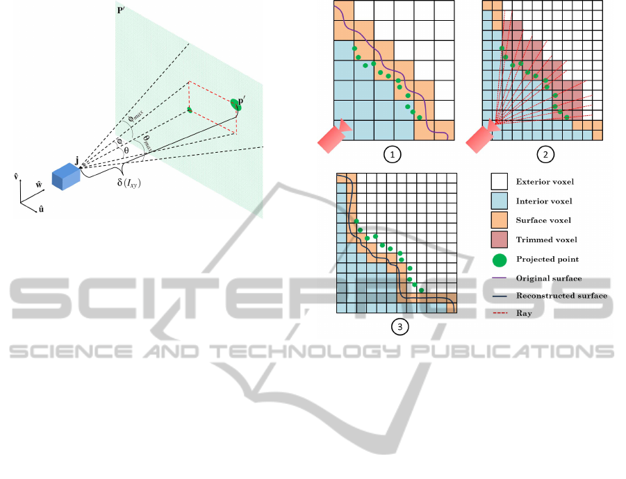
Figure 4: Projector and modified point cloud geometry.
the model. Rather than using the pixel space point
cloud, P, for raycasting, we project points outwards
from each projector,
ˆ
j, in such a way that points are
constrained within the projector frustum. This projec-
tion produces a new point cloud, P
0
.
P
0
=
∀
θ∈Θ
∀
φ∈Φ
p
0
(θ,φ) (7)
p
0
(θ,φ) = j + δ(I
x,y
)(
ˆ
w + sin(φ)
ˆ
v + αsin(θ)
ˆ
u) (8)
where θ and φ are a horizontal and vertical an-
gle along the projected image plane such that Θ =
{−θ
max
,...,θ
max
}, Φ = {−φ
max
,. . . ,φ
max
}, and θ
max
and φ
max
equal half of the horizontal and vertical field
of view of the GoPro Hero2 GTO cameras, α is the
disparity map’s aspect ratio, and
ˆ
w,
ˆ
u, and
ˆ
v are the
basis vectors of the projector.
Projectors are manually aligned in the volume to
coincide with the observed locations of the real ge-
ometry captured in each point cloud. To aid the user
in projector alignment, a marching cubes mesh is vi-
sualized within the volume so that the user may align
projections with respect to the mesh itself.
Once projectors are situated, rays are cast through
the viewports of the projectors. Rays originate at the
projector and are cast through each point in P
0
. Bre-
senham’s line algorithm (Bresenham, 1965) is con-
tinuously executed along each cast ray to find the next
voxel in the ray’s path. When the ray arrives at a voxel
containing a point, a boolean switch is triggered, set-
ting all following voxel occupancies greater than zero
(denoting that the voxel is outside of the surface), al-
tering the position of the eventual surface by redefin-
ing several zero-crossings along voxel edges (Fig. 5).
Once a ray passes through a voxel whose occupancy
is already greater than zero, the ray is terminated to
assure that no surfaces are trimmed unintentionally.
While ray casting cannot guarantee that all voxels
beyond the projected point cloud will be modified, the
Figure 5: Point clouds are manually aligned near existing
zero-crossings (orange to white boundary) (1). The volume
is subdivided to provide finer resolution, and rays are cast
from the projector through points (2). Voxels that lie beyond
the intersected points have their occupancies set greater than
zero, forming new zero-crossings for surfacing (3).
alterations to the volume occupancies generally occur
near walls, so cast rays do not diverge far enough to
miss any voxels. Additionally, projected point clouds
may be sampled with sub-pixel accuracy, effectively
minimizing the possibility of missed voxels.
The original resolution of a volume is decided
based on the properties of the sonar sensor and the
capabilities of the occupancy grid generation algo-
rithm. Since the original resolution of the volume
is only good enough to retain the details of the gen-
eral surface, the volume is subdivided prior to ray-
casting to increase the amount of detail achieved in
the areas which will be be modified by stereo data.
In most cases the volume can be subdivided one to
three times, yielding 8x to 512x as fine of a resolu-
tion. In order to facilitate smooth surface generation
using marching cubes, voxel occupancies are interpo-
lated trilinearly between subdivisions.
The algorithm is currently limited by memory
consumption. Even with efficient data storage struc-
tures, when large volumes are subdivided in excess,
they can exceed local memory. Due to the memory
limitations, the current algorithm cannot truly add the
same level of detail to the mesh as what is stored in the
stereo images. Future work includes multi-resolution
approaches to address this issue.
SurfaceReconstructionofAncientWaterStorageSystems-AnApproachforSparse3DSonarScansandFusedStereo
Images
165
5 VISUALIZATION
Marching cubes is run on the trimmed volume to pro-
duce a closed surface mesh, which can be visualized
and interacted with by researchers. In addition to
being able to manipulate the mesh in our visualiza-
tion software, the interpolated marching cubes mesh
is rendered in Cinema4D with a bump map and Fres-
nel shader to produce visually appealing static images
and flyby videos.
Our visualization software also grants the ability
to view errors in the level set reconstruction step by
using a signed distance function to color map error
onto vertices in the mesh. This visualization mode al-
lows archaeologists to understand which areas of the
reconstruction are likely to be most accurate.
6 RESULTS
The level set reconstruction method was applied to
three data sets, including a mushroom shaped cham-
ber (labeled “The Mush-room”) from a large water
gallery in Valletta, Malta, a complete water system
connected by two ROV deployment entrances (la-
beled “Site 3+4”) in Tal Gruwa, Gozo, and a com-
plete two-chambered cistern (labeled “The Archives”)
in Mdina, Malta. The stereo reconstruction method
was applied to The Mush-room.
Both horizontal and vertical sonar scans were col-
lected in The Mush-room. During ROV deployment,
the ROV was flown to a resting position, and two or-
thogonal 360
◦
sonar scans were collected. For more
information on the double sonar scanning configura-
tion see (Dobke et al., 2013). The collection of paired
scans was fused into an evidence grid. Data for The
Archives and Site 3+4 was collected by horizontally
scanning the cistern walls at 0.2 and 0.5 meter verti-
cal intervals, respectively (with no vertical scans, due
to hardware constraints). In some cases, scans would
be duplicated and translated to a different depth in the
evidence grid due to vertical symmetry in the walls of
the cistern. This is demonstrated in the three planes of
horizontal scans making up the lower channel in The
Mush-room’s evidence grid, and in some sonar scans
present in Site 3+4. Note however, that these are all
true 3D data sets as opposed to a single extruded hor-
izontal layer as in (Forrester et al., 2013). The evi-
dence grids for these three sites were processed into
meshes and visualized (Fig. 6).
The level set technique described in Sec. 3 worked
well in most situations, but caused ceilings to cave in
in regions where gaps existed in the data. For exam-
ple, the roof caved in on the Site 3+4 mesh due to a
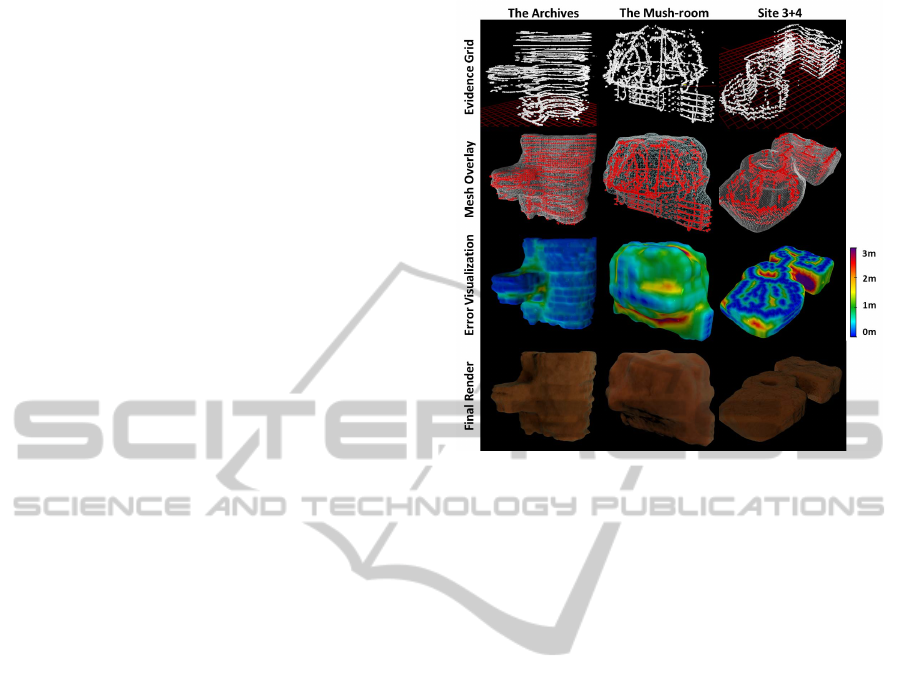
Figure 6: Results from applying the proposed 3D recon-
struction technique to three large data sets. The first col-
umn displays the sparsely populated evidence grid input.
The second column shows the reconstructed mesh overlaid
on the input. The third column shows the reconstructed
mesh colorized according to error in distance from the input
points. The final column displays Cinema4D renders of the
meshes given to archaeologists studying the sites.
lack of data in a circular central chamber. While these
dimples were a source of error for data sets consist-
ing of horizontal sonar scans, they were not present in
models where vertical sonar scans were included in
the evidence grid, such as The Mush-room.
Stereo images captured in The Mush-room were
processed into disparity maps and used to trim the
volume before resurfacing. Due to the poor qual-
ity of the GoPro Hero2 lenses and ROV lights, as
well as the cloudiness of the water and plainness of
features, it was extremely difficult to produce high-
quality disparity maps. Several methods, including
prepackaged frameworks such as OpenCV and MAT-
LAB’s CV Toolbox, as well as three custom algo-
rithms from stereo literature (Zitnick and Kanade,
2000) (Scharstein and Szeliski, 1998) (Nalpantidis
and Gasteratos, 2010) were utilized in attempts to
make good disparity maps. However, the distortions
from the hardware as well as the plainness of the
walls limited successful identification and matching
of salient features. The disparity maps from MAT-
LAB’s CV Toolbox were used. To demonstrate the
results of our algorithm, disparity maps were cleaned
and mirrored in some situations. The initial stereo re-
construction results were not given to archaeologists
GRAPP2014-InternationalConferenceonComputerGraphicsTheoryandApplications
166
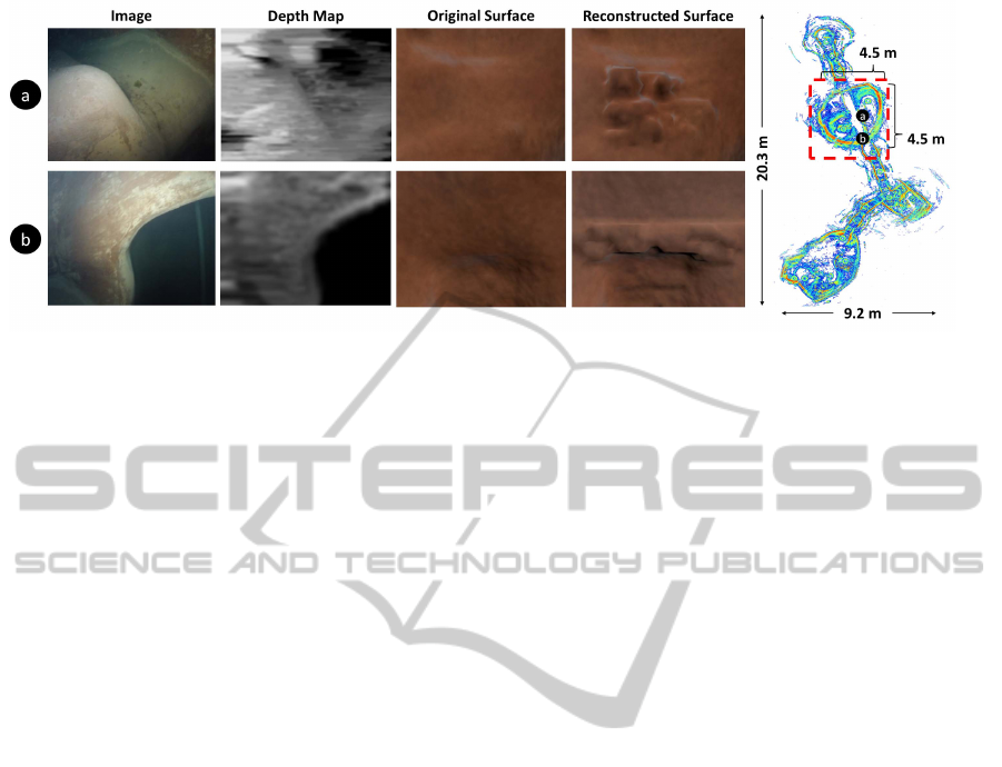
Figure 7: A sonar mosaic of the large water system containing The Mush-room (boxed in red). An archway (a) and a bump
(b), which were omitted from the sonar model, were captured with stereo cameras within the cistern and converted to disparity
maps. Due to the poor image quality feature matching was extremely difficult, and disparity maps were blurred and mirrored
before being projected into the volume. The 4.5x4.5x5.2 meter chamber was subdivided once to produce a 86x68x66 voxel
volume before raycasting (using an evidence grid cell size of 0.25 meters per voxel).
for study due to their variation from true geometry
data, but are presented here as a proof of concept.
Two distinct features in The Mush-room, an arch-
way and a large bump, were selected to add to the
volume. The archway disparity map was mirrored
to capture the entire feature, and both features were
trimmed from the volume. Even in the presence of
poor disparity maps, small features were reintroduced
successfully (Fig. 7).
7 CONCLUSIONS
This work has presented a process pipeline that ad-
dresses the problem of reconstructing geometric mod-
els from 3D sonar scans of underwater settings with
a micro-ROV. Surface reconstructions of underwater
settings inaccessible to humans were produced for
archaeological study using a small number of sonar
scans taken with a low-payload micro-ROV. In addi-
tion, the work has demonstrated a method of affixing
depth data captured in low cost stereo cameras to en-
hance rough sonar generated reconstructions. Previ-
ous work has successfully created 2D and extruded
2.5D models of closed underwater systems, while
the work here presents an initial success for a uni-
fied solution for surface reconstruction from 3D sonar
scans with stereo image enhancements. We were able
to successfully build representational surface recon-
structions given sparse 3D sonar data and integrate
locally higher resolution stereo data to add geometric
details when possible.
Three large sonar data sets were reconstructed to
test the proposed pipeline’s ability to handle sparse
3D sonar data. Two of the three data sets contained
only horizontal scans taken incrementally along the
depth of the site, and one data set was collected us-
ing both a vertical and horizontal sonar on the ROV.
All three of the reconstructed models are visually ap-
pealing, representative of true data, scaled according
to ground truth data, and useful for archaeological
study. The process of producing accurate disparity
maps from left and right images proved difficult un-
derwater, hampering the virtues of the second phase
of the pipeline. However, initial results have validated
the potential to incorporate higher resolution stereo
image data with the coarse resolution sonar data.
Several stages of the pipeline could be improved
in future work. An octree could be substituted for
the volume data structure in order to prevent mem-
ory limitations when subdividing voxels, replacing
marching cubes with a dual contouring method (Ju
et al., 2002) to prevent cracks and integrating multi-
resolution solutions for addressing the difference in
data density between stereo and sonar data. Projectors
could be automatically aligned in the volume using vi-
sual SLAM, or could have their positions determined
before runtime using a localization device on the ROV
such as an IMU or a SmartTether. With regards to
stereo hardware, the proposed stereo algorithm would
greatly benefit from cameras with a wider baseline
and lenses corrected for underwater photography. Ad-
ditionally, a more uniform structured lighting system
would be useful in illuminating the scene properly.
ACKNOWLEDGEMENTS
We would especially like to thank Dr. Jane Lehr and
2013 ICEX teams for their contributions. This ma-
SurfaceReconstructionofAncientWaterStorageSystems-AnApproachforSparse3DSonarScansandFusedStereo
Images
167

terial is based upon work supported by the National
Science Foundation under Grant No. 0966608.
REFERENCES
Adalsteinsson, D. and Sethian, J. A. (1994). A fast level set
method for propagating interfaces. Journal of Com-
putational Physics, pages 269–277.
Beall, C., Lawrence, B. J., Ila, V., and Dellaert, F. (2010). 3d
reconstruction of underwater structures. In Intelligent
Robots and Systems (IROS), 2010 IEEE/RSJ Interna-
tional Conference on, pages 4418–4423. IEEE.
Bresenham, J. E. (1965). Algorithm for computer control
of a digital plotter. IBM Systems journal, 4(1):25–30.
Campos, R., Garcia, R., and Nicosevici, T. (2011). Surface
reconstruction methods for the recovery of 3d mod-
els from underwater interest areas. In OCEANS, 2011
IEEE - Spain, pages 1–10.
Deng, S., Li, Y., Jiang, L., Cao, Y., and Zhang, J. (2011).
Variational surface reconstruction from sparse and
nonparallel contours for freehand 3d ultrasound. In In-
formatics in Control, Automation and Robotics, pages
51–58. Springer.
Dobke, A., Vasquez, J., Lieu, L., Chasnov, B., Clark, C.,
Dunn, I., Wood, Z., and Timothy, G. (2013). To-
wards three-dimensional underwater mapping with-
out odometry. In To appear in: Proceedings of the
18th International Symposium on Unmanned Unteth-
ered Submersible Technology (UUST).
Drap, P., Seinturier, J., Scaradozzi, D., Gambogi, P., Long,
L., and Gauch, F. (2007). Photogrammetry for virtual
exploration of underwater archeological sites. In Pro-
ceedings of the 21st International Symposium, CIPA
2007: AntiCIPAting the Future of the Cultural Past:
Athens (Greece), 01–06 October 2007. Citeseer.
Forney, C., Forrester, J., Bagley, B., McVicker, W., White,
J., Smith, T., Batryn, J., Gonzalez, A., Lehr, J., Gam-
bin, T., et al. (2011). Surface reconstruction of mal-
tese cisterns using rov sonar data for archeological
study. In Advances in Visual Computing, pages 461–
471. Springer.
Forrester, J., McVicker, W., Gambin, T., Clark, C., and
Wood, Z. J. (2013). Uncertainty visualization and hole
filling for geometric models of ancient water system.
In Proceedings of the 4th International Conference
on Information Visualization Theory and Application
(IVAPP).
Hurt
´
os, M., i Soler, X. C., and Salvi, J. (2009). Integration
of optical and acoustic sensors for d underwater scene
reconstruction. Instrumentation viewpoint, (8):43.
Ju, T., Losasso, F., Schaefer, S., and Warren, J. (2002).
Dual contouring of hermite data. ACM Trans. Graph.,
21(3):339–346.
Kazhdan, M., Bolitho, M., and Hoppe, H. (2006). Poisson
surface reconstruction. In Proceedings of the fourth
Eurographics symposium on Geometry processing.
Lorensen, W. E. and Cline, H. E. (1987). Marching cubes:
A high resolution 3d surface construction algorithm.
In ACM Siggraph Computer Graphics, volume 21,
pages 163–169. ACM.
Mahon, I., Pizarro, O., Johnson-Roberson, M., Friedman,
A., Williams, S. B., and Henderson, J. C. (2011). Re-
constructing pavlopetri: Mapping the world’s oldest
submerged town using stereo-vision. In Robotics and
Automation (ICRA), 2011 IEEE International Confer-
ence on, pages 2315–2321. IEEE.
McVicker, W., Forrester, J., Gambin, T., Lehr, J., Wood,
Z. J., and Clark, C. M. (2012). Mapping and visu-
alizing ancient water storage systems with an rov an
approach based on fusing stationary scans within a
particle filter. In Robotics and Biomimetics (ROBIO),
2012 IEEE International Conference on, pages 538–
544. IEEE.
Mullen, P., De Goes, F., Desbrun, M., Cohen-Steiner, D.,
and Alliez, P. (2010). Signing the unsigned: Robust
surface reconstruction from raw pointsets. In Com-
puter Graphics Forum, volume 29, pages 1733–1741.
Wiley Online Library.
Nalpantidis, L. and Gasteratos, A. (2010). Stereo vision
for robotic applications in the presence of non-ideal
lighting conditions. Image and Vision Computing,
28(6):940–951.
Nascimento, E., Campos, M., and Barros, W. (2009). Stereo
based structure recovery of underwater scenes from
automatically restored images. In Computer Graphics
and Image Processing (SIBGRAPI), 2009 XXII Brazil-
ian Symposium on, pages 330–337. IEEE.
Osher, S. and Fedkiw, R. (2003). Level set methods and dy-
namic implicit surfaces, volume 153. Springer Verlag.
Papaleo, L. and Puppo, E. (2004). Online Data Fusion for
building 3D models from acoustical range. Technical
Report DISI-TR-05-04, University of Genov.
Scharstein, D. and Szeliski, R. (1998). Stereo
matching with nonlinear diffusion. Interna-
tional Journal of Computer Vision, 28:155–174.
10.1023/A:1008015117424.
Schmidt, V. E. and Rzhanov, Y. (2012). Measurement
of micro-bathymetry with a gopro underwater stereo
camera pair. In Oceans, 2012, pages 1–6. IEEE.
Sethian, J. (2001). Evolution, implementation, and appli-
cation of level set and fast marching methods for ad-
vancing fronts. Journal of Computational Physics,
169(2):503–555.
Swirski, Y., Schechner, Y. Y., Herzberg, B., and Negah-
daripour, S. (2010). Underwater stereo using natural
flickering illumination. In OCEANS 2010, pages 1–7.
IEEE.
Zhao, H.-K., Osher, S., and Fedkiw, R. (2001). Fast surface
reconstruction using the level set method. In Vari-
ational and Level Set Methods in Computer Vision,
2001. Proceedings. IEEE Workshop on, pages 194–
201. IEEE.
Zitnick, C. L. and Kanade, T. (2000). A cooperative
algorithm for stereo matching and occlusion detec-
tion. Pattern Analysis and Machine Intelligence, IEEE
Transactions on, 22(7):675–684.
GRAPP2014-InternationalConferenceonComputerGraphicsTheoryandApplications
168
