
Hardware In the Loop for VDM-Real Time Modeling of Embedded
Systems
Jos
´
e Antonio Esparza Isasa, Peter W
¨
urtz Vinther Jørgensen and Peter Gorm Larsen
Department of Engineering, Aarhus University, Finlandsgade 22, Aarhus, Denmark
Keywords:
Hardware In the Loop (HIL), Modeling, Embedded Systems, VDM-RT.
Abstract:
This paper introduces a generic solution for gradually moving from a model of an embedded system to in-
clude embedded hardware and software components into the simulation of the model. Our technique enables
combined execution (co-execution) of system components models expressed in the VDM-RT formalism with
actual hardware/software realizations through the application of Hardware In the Loop (HIL) simulation. In-
troducing such component realizations in the simulation increases the fidelity of the simulation outcome, thus
enabling improved prediction of properties for the system realization.
1 INTRODUCTION
When developing embedded systems, complexity is
typically high and the possible design space with al-
ternative hardware components to use internally is
huge. In order to master complexity it is possible to
introduce precise abstract models that can be analysed
in different ways, one of them being simulation.
HIL simulation is a well known technique for ena-
bling incorporation of hardware components in the
simulation of some Device Under Test (DUT). This
technique is particularly helpful when comparing al-
ternatives in a simulation context and for ensuring the
fidelity of the models for the purpose of the analy-
sis required. A common application of HIL is test-
ing. In a testing scenario typically a hardware sys-
tem realization is tested against a simulated environ-
ment. The HIL simulation application proposed in
this paper is different, since we aim at using HIL as
a way to co-execute system models with real hard-
ware and software implementations deployed on tar-
get. In order to develop the system models we use the
Vienna Development Method Real-Time (VDM-RT)
dialect (Verhoef et al., 2006), which is a formal no-
tation enabling modeling and analysis of distributed
systems. VDM-RT is supported by an Eclipse-based
development platform called Overture (Larsen et al.,
2010a) that includes debugging capabilities and en-
ables incorporation of code written in Java (Nielsen
et al., 2012).
Modeling of the embedded system gives the abil-
ity to focus on the important development challenges
(e.g. correction of control algorithms) by applying a
higher level of abstraction to things of less impor-
tance (e.g. details of hardware drivers). VDM-RT and
its tool support further enables validation of timing
requirements (Fitzgerald and Larsen, 2007), inspec-
tion of the execution trace, generation of the imple-
mentation in a programming language (CSK, 2007;
Jørgensen and Larsen, 2013) and common consis-
tency mechanisms associated with a formal notation
(e.g. invariants and generation of proof obligations).
This paper is structured such that Section 2 intro-
duces the technologies used in our work. Then Sec-
tion 3 provides an overview of the setup for HIL si-
mulation of embedded systems expressed in VDM-
RT. This is followed by a prototype application us-
ing this setup in Section 4. Afterwards Section 5 de-
scribes the future work planned and Section 6 pro-
vides references for related work. Finally the paper
concludes in Section 7.
2 TECHNOLOGIES USED
This section presents the modeling, software and
hardware technologies that have been used to create
and explain the HIL setup.
2.1 Overture with support for VDM-RT
VDM supports different kinds of collections (sets, se-
quences and mappings) and has a significant focus on
209
Esparza Isasa J., Jørgensen P. and Larsen P..
Hardware In the Loop for VDM-Real Time Modeling of Embedded Systems.
DOI: 10.5220/0004698902090216
In Proceedings of the 2nd International Conference on Model-Driven Engineering and Software Development (MODELSWARD-2014), pages 209-216
ISBN: 978-989-758-007-9
Copyright
c
2014 SCITEPRESS (Science and Technology Publications, Lda.)

logic expressions in its way to model. In this paper we
deal with the VDM-RT notation, which is an object-
oriented notation enabling modeling of distributed
systems with an explicit notion of global time. In
VDM-RT it is possible to model different CPUs and
their connections using busses. Multiple threads can
exist at each CPU but at any point in time only one
thread can be executing at each CPU. In a simulation
all expressions and statements that are evaluated add a
default increase in global time when being performed.
Special cycles and duration statements exist for over-
ruling the default time increments either relative to
the CPU speed or with a fixed amount of time, re-
spectively.
2.2 Prototype Hardware
The DUT selected for this work is a System on Chip
(SoC). This kind of platform allows the combined de-
ployment of hardware and software components in
the same piece of silicon. We have considered it
appropriate for this work since it allows testing of the
HIL concept for VDM-RT in a more complete ma-
nner, taking into account both hardware and software
components. These components can act together or
in isolation while running on the same piece of hard-
ware.
In order to monitor the output produced by the
DUT on its digital buses we have used a logic ana-
lyzer (Saleae Logic 8). This device samples a number
of logical lines over a period of time. Any changes
on the lines during this period of time will be logged.
The logic analyzer selected for this work is connected
to a PC and it is possible to control it from custom
software, created using a Software Development Kit
(SDK) provided by the manufacturer.
3 HIL SETUP DESIGN
This section presents an overall description of the sys-
tem and its hardware and software architecture.
3.1 Overall System Description
The main objective of this system is to allow a step-
wise transformation of models of functionality into
components that implement that functionality. In or-
der to benefit from the models one can combine the
implemented components with the models of those
that still have not been implemented. In this way it is
possible to execute the components in a single model
implementation co-execution. This is the key idea be-
hind the HIL system presented in this paper, which
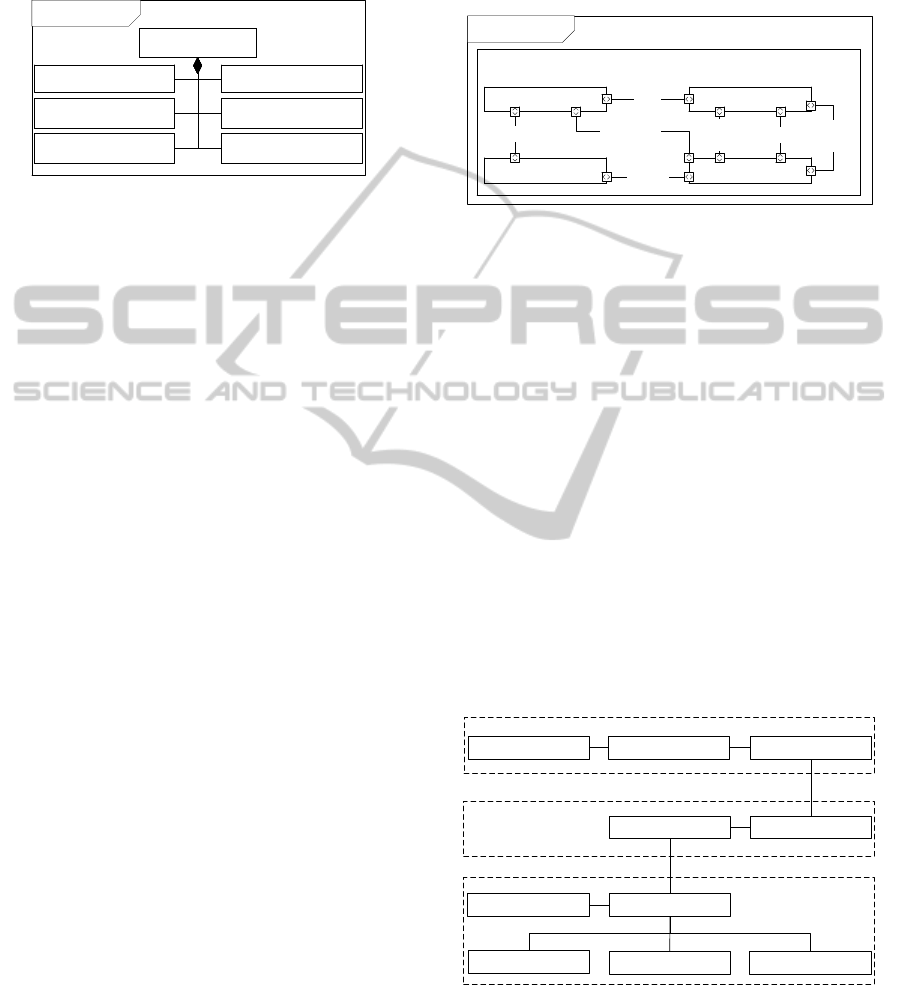
has not been applied previously for VDM-RT. Fig-
ure 1 illustrates this concept with an example based
on the design of an embedded system that enters three
stages: Acquire Data, Process and Provide Output.
The design of such a system starts with the mode-
ling of the complete system functionality. This is
illustrated in the upper row of Figure 1 (Full Mode-
ling). As it can be seen all the components are mod-
eled (represented on the VDM side) and no compo-
nents have been implemented on the target (the HW
side). After the system has been modeled the com-
ponent providing the Process functionality is imple-
mented. It is the intention to substitute the modeled
Process component with its correspondent implemen-
tation and still use the rest of the model for system
simulation. This approach is shown in the lower row
of Figure 1. At this point it is possible to start the sys-
tem simulation on the VDM-RT side in the Acquire
Data stage and then the HIL system will hand-over
the execution of the Process stage to the implementa-
tion deployed on target. Once Process has completed,
execution will return from the target embedded sys-
tem to the VDM-RT model of this functionality and
continue with the Provide Output stage.
VDMHW
Acquire Data Process
Provide Output
VDMHW
Full
Modelling
Modelling
with HIL
Acquire Data
Process
Provide Output
Figure 1: Device modeling and combined device modeling
with HIL.
By applying the approach proposed in this paper the
design engineer is able to benefit from: 1) the ex-
pressiveness of VDM-RT to represent real-time con-
straints and system properties 2) the simulation capa-
bilities of Overture and 3) the insight gained through
prototyping using a combined-modeling prototyping
approach.
3.2 Hardware
In order to create a system that supports the func-
tionality presented above we have used a number of
external hardware components. This hardware ar-
chitecture is presented in Figure 2 using a System
Modeling Language
1
(SysML) Block Definition Dia-
1
SysML (Sandford Friedenthal, 2008) extends the Uni-
fied Modelling Language (UML) and allows modelling of
both hardware and software in the same system description.
In our work we use it for describing the structural and dy-
namical aspects of the HIL setup.
MODELSWARD2014-InternationalConferenceonModel-DrivenEngineeringandSoftwareDevelopment
210
gram (BDD). This diagram shows the components
that comprise the system in a hierarchical manner
without showing their connections. These compo-
nents are:
bdd HIL System
«block»
HIL setup
«block»
Stimuli Provider
«block»
DUT
«block»
Logic Analyzer
«block»
Embedded Software
«block»
Embedded Hardware
«block»
Workstation
Figure 2: Main components of the HIL setup shown in a
SysML BDD.
HIL Setup: is the top level representation of the HIL
system. This block represents the system as a
whole and not with a concrete piece of hardware.
Workstation: is a computer running Overture and
the required software infrastructure to communi-
cate with the rest of the hardware components
connected to it.
DUT: is the external device that contains a partial im-
plementation of the system. This partial imple-
mentation contains a certain functionality that will
be triggered from the model execution. The DUT
is composed of Embedded Software and Embe-
dded Hardware, i.e. the functionality under test
can be implemented in hardware and/or software
components.
Stimuli Provider: is an electronic device able to pro-
vide digital signals to the DUT. These external in-
puts can represent any device with a logical inter-
face, e.g. a sensor measuring physical parameters
or a different digital hardware block.
Logic Analyzer: is a Digital Acquisition (DAQ)
board enabling capturing of the evolution of a
number of digital signals over time. The main pur-
pose of this block is to monitor the digital outputs
provided by the DUT.
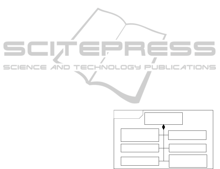
In order to show the connection between the most
relevant hardware blocks we have used a SysML In-
ternal Block Diagram (IBD), presented in Figure 3.
We have used standard ports to represent discrete lo-
gical communication and flow ports to represent con-
tinuous signals. The Workstation uses USB and se-
rial busses to communicate with the rest of the blocks
presented in the IBD. The communication between
the Stimuli Provider and DUT is made through a lo-
gical bus that maps the Stimuli Provider outputs to
the DUT inputs. The same kind of bus is used be-
tween the DUT and the Logical Analyzer to monitor
the DUT output values. Additionally two dedicated
inputs in the Logic Analyzer are used to analyze a
DUT Pulse Width Modulated (PWM) output and the
function execution time (Duration Pin).
Serial Bus
Duration
Pin
Serial Bus
Logical
Bus
Logical
Bus
PWM
USB
ibd HIL System
:DUTStimuli provider
:Logic Analyzer:Workstation
<<block>>
HIL Setup
Figure 3: SysML Internal Block Diagram showing the hard-
ware connections to the DUT.
The software components running on the Workstation
are presented in the Section 3.3. The Embedded Soft-
ware and Hardware blocks are not discussed since
they are dependent on the system under study. An
example of those will be given in section 4.
3.3 Software and Modeling
Components
The workstation software and modeling components
of the HIL setup are shown in relation to each other in
the class diagram in Figure 4. Each of the components
are treated individually in the description below. To
supplement the description of the software and mode-
ling structure in this subsection, the execution flow
will be covered in Section 4.2.
1
1
1
1
1
1
1
1
11
Overture
Java
.NET
*
1
1
1
1
1
DUT Controller
Log
VDM-RT ModelVDM-RT Interpreter Hardware Proxy
Stimuli Controller
Java BridgeHIL Proxy
HIL Component
DAQ Driver
Figure 4: The software and modeling components of the
HIL setup shown in a class diagram.
VDM-RT Interpreter: executes the VDM-RT
Model representing the embedded system under
consideration.
HardwareIntheLoopforVDM-RealTimeModelingofEmbeddedSystems
211
Hardware Proxy: specifies the interface of the hard-
ware being controlled from the VDM-RT exe-
cution. All invocations are initiated in VDM-RT
and communicated through the Java Bridge before
they reach the physical hardware.
Java Bridge: enables delegation of VDM-RT func-
tionality execution to Java. In this way one can
invoke a VDM-RT operation or function and have
the body specified and executed as a Java method.
The Java Bridge does automatic conversion and
transferring of input and output values between
Java and VDM-RT.
HIL Proxy: is a thin software component that ac-
cepts inputs from the Java Bridge inside Over-
ture and relays the invocations originating from
the VDM-RT execution to a HIL component re-
sponsible for communicating with the hardware
used in the HIL setup. The HIL proxy is interoper-
ability glue that enables communication between
Overture and the hardware.
HIL Component: is responsible for communicating
directly with the hardware used in the HIL setup
through serial connections. Although we only
connect to a single instance of the HIL Compo-
nent it would be possible to extend this to multiple
instances as indicated in Figure 4 and described in
Section 5.5. Finally, the HIL Component uses the
Log for writing the data acquired from the DAQ
to the file system.
Stimuli Controller: instructed by the HIL Compo-
nent the Stimuli Controller provides the DUT with
input signals prior to executing the functionality
under test.
DUT Controller: instructs the external DUT to exe-
cute some function in software or hardware.
DAQ Driver: provides the software interface ena-
bling the HIL component to launch the DAQ so
the data needed can be acquired from the DUT
execution.
4 HIL SETUP PROTOTYPE
This section presents the initial setup for the HIL sys-
tem by describing the prototype as well as the co-
execution of the model and the partial implementa-
tion.
4.1 Prototype Description
The current prototype for this case implements a con-
trol algorithm for a mechanical device. This algo-
rithm is composed of several stages: 1) Initialization,
2) Regulation Loop and 3) Results Logging. We have
modeled the algorithm in VDM-RT and continued by
producing a preliminary implementation of the Re-
gulation Loop that can be deployed to target. The
aim of this first approach is to combine in a single
execution trace the models of Initialization and Re-
sults Logging with the implementation of Regulation
Loop that is deployed on the DUT. Additionally, we
are interested in measuring the execution time of the
regulation cycle on real hardware in order to verify if
real-time constraints are met. This real-time informa-
tion will also be incorporated to the VDM-RT models
afterwards. The following sections elaborate on the
structure and the functionality provided by the Embe-
dded Hardware and Software blocks which the DUT
is composed of.
4.1.1 Embedded Hardware
The system has been implemented in a PSoC 5 with
an ARM Cortex M3 processor and the additional
hardware components presented in the SysML BDD
presented in Figure 5. These components support
the communication with external logical interfaces
(Actuator Logical Interface and Sensor Logical Inter-
face), the PWM control of an actuator, the commu-
nication with the workstation running the VDM-RT
model (UART) and finally the pin toggling for time
measurements (Duration Pin).
«block»
Embedded Hardware
«block»
UART
«block»
Sensor Logical
Interface
«block»
PWM
«block»
Actuator Logical
Interface
«block»
Duration Pin
«block»
ARM CPU
bdd DUT EH
Figure 5: The Embedded Hardware (EH) of the DUT shown
in a SysML BDD.
Additional details on these components can be found
in the documentation provided by the manufac-
turer (Cypress, 2013).
4.1.2 Embedded Software
The embedded software executing on the DUT is de-
ployed on the ARM processor. The software is com-
posed of three main blocks: Hardware Drivers, Func-
tionality Under Test (FUT) and HIL Support as shown
in Figure 6. The Hardware Drivers provide the ne-
cessary software support to interface the hardware
MODELSWARD2014-InternationalConferenceonModel-DrivenEngineeringandSoftwareDevelopment
212
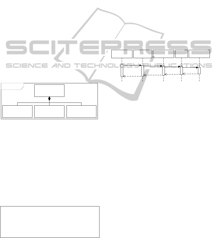
blocks from software. HIL Support contains the logic
to start the execution of the FUT upon request from
the DUT Controller running on the workstation. This
functionality is structured in three phases:
1. Wait for Command: The system waits for a pos-
sibly parametrized command over UART describ-
ing the functionality to execute.
2. Serve HIL Request: The system initiates the exe-
cution of the FUT. This can be surrounded by pin
toggling operations to measure the execution time
of the function. Optionally additional pin toggling
can be performed inside the function to measure
the time it takes to reach different points during
the execution.
3. Return to DUT Controller: Once the system has
completed the execution of the FUT it returns to
the DUT controller so it can stop signal sampling
and notify the model execution environment to
resume model execution. Additionally it can re-
turn result values produced by the execution of the
FUT.
«block»
Embedded
Software
«block»
Hardware
Drivers
«block»
HIL Support
«block»
Functionality
Under Test
bdd DUT ES
Figure 6: The Embedded Software (ES) of the DUT shown
in a SysML BDD.
The FUT in this case is a control sequence im-
plemented in C and outlined in code Listing 1.
This presents a regulation cycle composed of three
phases sensor values retrieval (readSensors), cal-
culation of the regulation parameters (regulate),
and finally command of actuators according to those
(produceLogicalOutput and modifyPWM). Note
that these functions have been surrounded by pin to-
ggling instructions (toggleDurationPin) to enable
the calculation of execution time.
Listing 1: Control sequence implementation.
toggleDurationPin () ;
readSen s o r s () ;
regu l a t e () ;
pro d u c e L o g i c a l O u t p u t () ;
modif y P W M () ;
toggleDurationPin () ;
4.2 Model Execution
Hardware control is initiated through the Hardware
Proxy that specifies the functionality of the physi-
cal hardware accessible to the VDM-RT model (e.g.
providing the DUT with input signals or performing
hardware or software computations). Using the dura-
tion or cycles statements the modeller can specify the
number of cycles (for the VDM-RT CPU) or absolute
time it takes to execute a hardware or software func-
tion. The global time of VDM-RT will then progress
accordingly. Furthermore, the Java Bridge executes
atomically, i.e. no thread will be swapped in until exe-
cution returns to the model.
Invocations to the Hardware Proxy are initiated
in the VDM-RT model, and then relayed by the HIL
Proxy to the HIL Component as shown in Figure 7.
:Hardware
Proxy
:HIL
Proxy
:HIL
Component
Send(cmd)
Send(cmd)
:VDM-RT
Model
Send(cmd)
operation()
:VDM-RT
Interpreter
Figure 7: Sequence diagram showing how invocations orig-
inating from the VDM-RT interpreter reaches the HIL Com-
ponent.
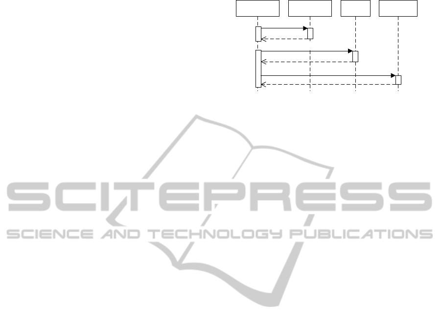
From here the HIL Component either invokes the
Stimuli Controller or the DUT Controller. This pro-
cess is represented with a UML sequence diagram
in Figure 8. In this diagram the HIL Component
first signals the Stimuli Controller to supply the DUT
with input signals. Next it launches the DAQ using
the corresponding driver and finally the DUT is in-
structed to perform some computation via the DUT
Controller. While the DUT is executing the DAQ is
continuously sampling the state of the DUT, which is
logged to a file at the end of execution. Invocations
from the VDM-RT interpreter, Hardware Proxy, HIL
Proxy and HIL Component (including data logging)
have been omitted from Figure 8.
4.3 HIL Execution Results
The co-execution of the model and the implemen-
tation made it possible to validate the real-time be-
haviour of the FUT component as well as the correct
operation of its control logic. We have been able to
validate that the time slot allocated to the regulation
cycle is not overrun and obtained a precise time mea-
surement that can be incorporated to the models. Ad-
ditionally it has been possible to exercise the im-
HardwareIntheLoopforVDM-RealTimeModelingofEmbeddedSystems
213
plemented control logic together with the modeled
components on a number of scenarios. Finally, this
HIL setup has facilitated the stepwise implementation
from a system level design approach.
Our approach is further supported by tools for au-
tomatic generation of the system implementation. For
software components it is possible to produce Java
and C++ from VDM using code generators (CSK,
2007; Jørgensen and Larsen, 2013). However, for
hardware components there is currently no support
for generating the implementation in a hardware de-
scription language. Even though automatic hardware
generation is not available in VDM-RT this language
can be used to study component-level time constraints
and to some extent hardware/software partitioning
problems (Isasa et al., 2012).
5 FUTURE WORK
The work presented in this paper is a proof of con-
cept showing that HIL can be implemented for VDM-
RT. We are planning to extend this initial prototype so
more complex analysis can be performed. Such anal-
ysis would enable study of further real-time aspects
of the system, system response in the analog domain
and the application of this setup in a HIL network.
5.1 Profiling Function Execution
As described above it is possible with the current
HIL setup to measure the execution time of the im-
plemented functionality by manual analysis of the
waveforms captured. With the current HIL setup one
would have to annotate the VDM-RT model with the
execution time manually, i.e. using the duration state-
ment parametrized with a number indicating the exe-
cution time in nanoseconds. This future work item
suggests improving this process so that the VDM-RT
model execution is automatically annotated with the
execution time as measured from the DUT.
In this scenario, invocations originating from the
Hardware Proxy are all intercepted by the HIL Proxy
which has access to the core functionality of the Over-
ture platform such as the AST and the interpreter exe-
cuting the VDM-RT model. Thus it would be possible
to extend on the HIL Proxy and inject the duration
statement programmatically using the Java function-
ality of the Overture platform. In this way it is po-
ssible to make the global time of VDM-RT progress
by the time measured from the execution of the DUT
function transparently when this is being executed by
the VDM-RT interpreter.
:HIL
Component
:Stimuli
Provider
:DAQ
Driver
:DUT
Controller
Write(data)
LaunchDAQ()
Write(data)
Figure 8: Sequence diagram showing the Workstation com-
municating with the DAQ Driver and the DUT Controller.
5.2 Specification and Validation of RT
Deadlines
The work of (Fitzgerald and Larsen, 2007) presents
an extension to VDM-RT, enabling the validation of
system-level timing properties. Validation conjec-
tures are descriptions of temporal relations between
system level events, which can be evaluated over the
VDM-RT execution trace. Later this work has been
extended in (Ribeiro et al., 2011) to include run-
time validation. Predefined standard forms of valida-
tion conjectures have been defined, directly support-
ing the validation of a deadline or separation between
two events, called the trigger and the response. The
trigger event could be the press of a button, and the
corresponding response may be the update of a dis-
play. From the standard forms, more specific vali-
dation conjectures can be constructed. In this way
it is possible to specify system level timing proper-
ties and then automatically validate these against the
execution time as measured from the execution of the
DUT. In case validation conjectures are violated dur-
ing the execution of a VDM-RT model this can be
analysed graphically using the RealTime Log Viewer
available in the Overture tool (Larsen et al., 2010b).
5.3 Analog Data Acquisition
The current HIL setup only supports the acquisition
of digital signals. We would like to extend this to the
acquisition of analog signals so it will be possible to
monitor other kind of hardware blocks such as Digital
to Analog Converters or analog sensors among others.
We have done a preliminary integration of an ana-
log acquisition board with the HIL setup proposed in
this paper using a preliminary SDK. The current re-
sults show that it is possible to use this device in a
similar way to the logic analyzer. However we still
need to explore this approach further.
MODELSWARD2014-InternationalConferenceonModel-DrivenEngineeringandSoftwareDevelopment
214

5.4 Power and Energy Consumption
Profiling
Analog DAQ enables measuring of energy consumed
by the DUT using a shunt resistor for monitoring the
evolution of voltage over time in the resistor. Volt-
age variations could be logged for later processing in
order to calculate consumed energy and power of dif-
ferent components
This allows the engineer to profile the energy con-
sumption of different components in the system at dif-
ferent levels of abstraction. One of the possibilities
is to profile the energy consumption of the hardware
blocks used during system operation. A second pos-
sibility is to profile the energy consumption of code
sections by annotating the different software routines
in the real-time model with figures describing the en-
ergy consumed. This can be extended to profiling of
energy consumption for communication with exter-
nal systems, by monitoring the energy consumed of
the communication interfaces. These measurements
could be used for annotating the VDM-RT model and
associated with the communication abstractions avail-
able in VDM-RT.
5.5 Multiple HIL Nodes
The current HIL setup only considers the situation
where the HIL Proxy connects to a single HIL com-
ponent. However, for situations where the system is
composed of multiple hardware platforms communi-
cating over a network while being physically far apart,
it may be better to have a HIL Component for each of
the hardware platforms composing the system. In this
way the HIL Proxy can be connected to several HIL
Components each being responsible for performing
DAQ and data logging on a hardware platform. This
case was briefly mentioned in Section 3.3 and indi-
cated by the multiplicity of the association between
the HIL Proxy and HIL Component in the class dia-
gram in Figure 4.
5.6 Waveform Analysis
To ease the analysis of logical signals it is crucial
to use a tool that enables their graphical representa-
tion over time and automates at least partial waveform
analysis. Current software for this purpose allows
the definition of expressions to evaluate signal proper-
ties automatically and the definition of time markers
to measure time intervals among other facilities. We
would like to benefit from these features by using an
ad-hoc signal analysis tool such as IMPULSE (Haber,
2013) or GTKWave (GTKWave, 2013). In order to
use these tools the HIL setup proposed in this paper
must implement the generation of time logs in Value
Change Dump format (IEEE, 1996). Using this for-
mat will allow the generation of smaller files that are
easier to handle by the tools.
6 RELATED WORK
HIL simulation has been used extensively in safety-
critical sectors such as avionics (Peleska, 2002)
and automotive (Schuette and Waeltermann, 2005;
Schulte et al., 2012). It has primarily been used in
those domains for testing, which would otherwise be
very expensive using traditional approaches such as
physical prototyping. However, the industrial take-
up of HIL testing is spreading rapidly to less critical
domains (Fathy et al., 2006), also due to the speed
of modern processors as well as different commercial
solutions arising (NI, 2012; MathWorks, 2011).
Currently there are several approaches to HIL.
This technique can be used to provide a certain DUT
with a simulated environment in order to validate its
control logic. Chudy et al. use a HIL component
running a flight simulation composed of a number
of physical models to test avionic systems (Chudy
and Rzucidlo, 2012). A similar approach is used
in (Schlegel et al., 2002) to test an automatic gearbox.
The approach presented in this paper differs from
the ones described above since the HIL component
is used so partial system implementations can be co-
executed with a VDM-RT model, thus enabling step-
wise system development. Additionally VDM-RT fa-
cilitates the development of quality systems using the
consistency mechanisms previously described. This
means that no model of any kind (neither physical,
nor logical) is executing in the HIL component.
Orth et al. propose the application of Petri nets
to develop Programmable Control Logic software
and describe its combination with Software/Hard-
ware/System in the loop simulation (Orth et al.,
2005). However the setup used in their case study is
specific for industrial automation and not as generic
as the one proposed in this paper. Previous work also
exists concerning transformation of Petri nets models
into asynchronous hardware components (Carmona
et al., 2004). By combining our approach with the
ideas proposed by Orth et al. and the transformation
approach suggested by Carmona et al. one could de-
velop a similar setup to support the co-execution of
Petri net models with hardware/software system real-
izations.
HardwareIntheLoopforVDM-RealTimeModelingofEmbeddedSystems
215

7 CONCLUDING REMARKS
In this paper we have presented the initial work
we have carried out to enable HIL simulation using
models written in VDM-RT. This proof-of-concept
demonstrates the potential of our approach but nat-
urally there is significant future work remaining to
make this a useful feature for industrial use.
REFERENCES
Carmona, J., Cortadella, J., Khomenko, V., and Yakovlev,
A. (2004). Synthesis of asynchronous hardware from
petri nets. In Advances in Petri Nets, LNCS 3098,
pages 345–401. Springer.
Chudy, P. and Rzucidlo, P. (2012). Hil simulation of a
light aircraft flight control system. In Digital Avionics
Systems Conference (DASC), 2012 IEEE/AIAA 31st,
pages 6D1–1–6D1–13.
CSK (2007). VDMTools homepage.
http://www.vdmtools.jp/en/.
Cypress (2013). http://www.cypress.com/. Cypress official
website.
Fathy, H. K., Filipi, Z. S., Hagena, J., and Stein, J. L.
(2006). Review of Hardware-in-the-Loop Simulation
and its Prospects in the Automotive Area. In Proc.
SPIE 6228, Modeling and Simulation for Military Ap-
plications. http://dx.doi.org/10.1117/12.667794.
Fitzgerald, J. S. and Larsen, P. G. (2007). Triumphs and
Challenges for the Industrial Application of Model-
Oriented Formal Methods. In Margaria, T., Philippou,
A., and Steffen, B., editors, Proc. 2nd Intl. Symp. on
Leveraging Applications of Formal Methods, Verifica-
tion and Validation (ISoLA 2007). Also Technical Re-
port CS-TR-999, School of Computing Science, New-
castle University.
GTKWave (2013). http://gtkwave.sourceforge.net/. GTK-
Wave official website.
Haber, T. (2013). http://toem.de/index.php/impulse. IM-
PULSE official website.
IEEE (1996). IEEE Standard Hardware Description Lan-
guage Based on the Verilog(R) Hardware Description
Language. IEEE Std 1364-1995.
Isasa, J. A. E., Larsen, P. G., and Bjerge, K. (2012). Sup-
porting the Partitioning Process in Hardware/Software
Co-design with VDM-RT. In Proceedings of the 10th
Overture Workshop 2012, School of Computing Sci-
ence, Newcastle University.
Jørgensen, P. W. and Larsen, P. G. (2013). Towards an Over-
ture Code Generator. In Submitted to the Overture
2013 workshop.
Larsen, P. G., Battle, N., Ferreira, M., Fitzgerald, J., Laus-
dahl, K., and Verhoef, M. (2010a). The Overture Ini-
tiative – Integrating Tools for VDM. SIGSOFT Softw.
Eng. Notes, 35(1):1–6.
Larsen, P. G., Lausdahl, K., Ribeiro, A., Wolff, S., and Bat-
tle, N. (2010b). Overture VDM-10 Tool Support: User
Guide. Technical Report TR-2010-02, The Overture
Initiative, www.overturetool.org.
MathWorks (2011). http://www.mathworks.com/. Simulink
official website.
NI (2012). Hardware-in-the-Loop (HIL) Testing.
http://www.ni.com/hil/.
Nielsen, C. B., Lausdahl, K., and Larsen, P. G. (2012).
Combining VDM with Executable Code. In Derrick,
J., Fitzgerald, J., Gnesi, S., Khurshid, S., Leuschel,
M., Reeves, S., and Riccobene, E., editors, Abstract
State Machines, Alloy, B, VDM, and Z, volume 7316
of Lecture Notes in Computer Science, pages 266–
279, Berlin, Heidelberg. Springer-Verlag. ISBN 978-
3-642-30884-0.
Orth, P., Bollig, A., and Abel, D. (2005). Rapid Prototyping
of Sequential Controllers With Petri Nets. In Proceed-
ings of the 16th IFAC World Congress.
Peleska, J. (2002). Hardware/Software Integration Testing
for the new Airbus Aircraft Families. In Schiefer-
decker, I., K
¨
onig, H., and Wolisz, A., editors, Test-
ing of Communicating Systems XIV. Application to
Internet Technologies and Services, pages 335–351.
Kluwer Academic Publishers.
Ribeiro, A., Lausdahl, K., and Larsen, P. G. (2011). Run-
Time Validation of Timing Constraints for VDM-RT
Models. In Wolff, S. and Fitzgerald, J., editors, Pro-
ceedings of the 9th Overture Workshop, number ECE-
TT-2 in Technical Report Series, pages 4–16.
Sandford Friedenthal, Alan Moore, R. S. (2008). A Prac-
tical Guide to SysML. Morgan Kaufman OMG Press,
Friendenthal, Sanford, First edition. ISBN 978-0-12-
374379-4.
Schlegel, C., Bross, M., and Beater, P. (2002). Hil-
simulation of the hydraulics and mechanics of an au-
tomatic gearbox. In Proceedings of the second Inter-
national Modelica Conference, pages 67–75.
Schuette, H. and Waeltermann, P. (2005). Hardware-in-the-
Loop Testing of Vehicle Dynamics Controllers – A
Technical Survey. In Proc. of SAE05, Detroit. SAE.
SAE Technical Paper 2005-01-1660.
Schulte, T., Kiffe, A., and Puschmann, F. (2012). Hil si-
mulation of power electronics and electric drives for
automotive applications. In Electronics, volume 12,
pages 130–135.
Verhoef, M., Larsen, P. G., and Hooman, J. (2006). Mode-
ling and Validating Distributed Embedded Real-Time
Systems with VDM++. In Misra, J., Nipkow, T., and
Sekerinski, E., editors, FM 2006: Formal Methods,
Lecture Notes in Computer Science 4085, pages 147–
162. Springer-Verlag.
MODELSWARD2014-InternationalConferenceonModel-DrivenEngineeringandSoftwareDevelopment
216
