
Smart Fabrication of Robotic Systems
A Project with University Students
Vanessa Nickel, Pablo Ottersbach, Robert Reichert and Michael Schäfer
Institute of Computer Science, University of Applied Sciences Ruhr West, Tannenstraße 43, 46240, Bottrop, Germany
Keywords Smart Technology, RepRap, Prototyping, Robotic Systems, Copter, Camera Flight, FPV-flight,
CNC-Laser-Cutter, Beech Plywood.
Abstract This paper describes the progression of new construction technologies to rapid prototype multicopters.
Based on ideas of the growing maker-community, university students used 3D-printing and laser-cutting
technologies to build copters with individual features. In this case a flight without visual contact should be
realised by mounting a camera in front of the copter. Both technologies were used in competition and the
better requirements satisfying copter was built.
1 INTRODUCTION
Since a few years the RepRap is conquering the
market (N. Gershenfeld, 2012). This is a 3D-printer,
which is used for Rapid Prototyping and produces
components by printing thermoplastic with high
accuracy (Possibility of reconstruction of dental
plaster cast from 3D digital study models, 2013). Its
name RepRap is the shortcut for Replicating Rapid
Prototyper. Due to falling investment and running
costs (McKinsey & Company, Loc. Cit., 2013) a
large amount of people are using this process now.
The advantageous in contrast to different
processes are the endless possibilities to create and
construct (D. Jijotiya, Dr. P. Lal Verma, 2013). The
RepRap is able to print a lot of components, if
necessary by using a supporting structure. So it is
also able to replicate itself (T. Simonite, 2010).
With these newest technology students built a
Copter supplied in their project work. The target is
the knowledge about different materials and to
choose the best components for the copter.
Another possibility is the construction of the
frame with beech plywood using a CNC laser cutter.
The frame is designed of beech plywood with
positioning of components in a different way
compared to the printed model based on different
characteristics.
Furthermore the results of printed components
were compared with cut-off-pieces. Thereby is
shown the interest of the particularities of design and
manufacturing problems as well as the advantages
and disadvantages of the processes and the
constructed frames.
To realize a flight view without viewing the
copter, a Go Pro camera is installed at the front of
the fuselage. The image is transferred to fat shark
glasses which contain a small monitor inside.
2 RELATED WORK
2.1 Copter
By now there are a lot of different types of copters
buyable for home-use: Either you can buy it as an
already functionable copter or only the single
components to build your own.
Copters are professional-used, too; for example to
provide dismounted soldiers with aerial
reconnaissance capabilities and support in complex
urban environments (Hou, M., Ho, G., Arrabito, G.
R., Young, S., Yin, S., 2013).
There are many differences between preinstalled
copters: From basic models, which are only be
capable to fly, over non professional FPV drones,
like the parrot AR Drone, to high professional
Copters used by industry. Meanwhile they are able
to be controlled with smartphones, so a separate
radio-remote-control isn’t needed (Årzén, K. E.,
2013, Zimmermann, A., 2012).
To create your own copter there are many
345
Nickel V., Ottersbach P., Reichert R. and Schäfer M..
Smart Fabrication of Robotic Systems - A Project with University Students.
DOI: 10.5220/0004699103450350
In Proceedings of the 3rd International Conference on Sensor Networks (SENSORNETS-2014), pages 345-350
ISBN: 978-989-758-001-7
Copyright
c
2014 SCITEPRESS (Science and Technology Publications, Lda.)

choices: In the trade there are complete construction
kits availabe which only need to be put together;
moreover exist a lot of construction manuals to
fabricate your own copter by yourself.
The disadvantages of construction-kits are
manifold:
The arms are often airtight, so the air resistance is
much higher; this reduces the flight-time
Upgrade the copters with subsequently-installed-
cameras is not easy; there could arise problems
If they have a crash and no predetermined-
breaking-points or a very robust chassis perhaps it
will break. The consequence would be an
expensive repair
The radio-range is low, maximal like the visual
range of the copter
They haven’t a negative pitch or the funk-control
doesn’t let switch itself
Conclusion: Bad or too cheap components
induces unsafely flights and a low flight-stability.
The biggest Problem with all this flying
machines is the power of the battery; because of this
the TU München already has developed a method to
reach endless flight-time with a Laser and a solar-
plate fixed at the Ground of the Copter (Technical
University of Munich, 2010). If the Laser irradiates
the plate, the Drone gets more energy. The
disadvantage is that all the time a laser has to shine
on it.
2.2 RepRap
To build a copter with a 3D-printer, there are five
different types of 3D-printer-techniques:
Stereo-lithography (SLA) is the oldest method of
3D-printing: The liquid material is contained in a
box where a laser hits on the molecules which is
why they connect to each other. A support
structure is necessary which easy can be removed
after.
Selective laser sintering (SLS) use powdery
material which can be plastic, metal or ceramic.
The layers apply with a roll-mechanism and will
be fuse by a laser. A support structure isn’t
necessary, only when printing a component
without a continuous connection it is needed. An
after-treatment is absolutely necessary because it
isn’t possible to prevent that the powder particles
near the printed components sinter, too. Depending
on the complexity and the material of the
component it isn’t easy to remove the support-
structure a sand or glass bead blasting is needed.
Fused Deposition Modelling (FDM) uses a thick
plastic string which will be heated up by an
extruder and cools down on a plate, while creating
the final form. A support-structure as well as an
after-treatment to remove it is necessary.
Laminated Object Manufacturing (LOM) uses
paper or plastic foils which will be glued layer by
layer. After every layer it has to rework the
contours with a cutting tool. The after-treatment is
only to remove the cut pieces.
Three-dimensional-Printing (3DP) works like
the SLS-technique with powdery material, but uses
a print head and a binder to connect the powder.
An after-treatment isn’t necessary.
2.3 CNC-Laser-Cutter
To build a copter with a CNC-laser-cutter there are
many possibilities. The following are the most
common:
Gas laser are classified in chemical laser, excimer
laser and metal-vapor laser. All are powered by a
chemical reaction
Dye laser use an organic dye as laser medium
Solid-state laser which use a solid gain medium
Semiconductor laser belongs to the group of
solid-state lasers
3 MACHINES AND MATERIALS
3.1 RepRap Printer
For this project we used the FDM-printers BFB-
3000 and 3D Touch. Both use the thermoplastic-
materials PLA and ABS. In earlier times of using the
printers PLA had turned out as the better material for
large parts: It has sufficient capacity, and a relatively
low thermal distortion. ABS has sufficient capacity,
too, but the thermal distortion is higher, so the
printed layers remove from each other during the
printing process and the components becomes
unusable immediately.
Useable components are only producible by
printing when prevailing optimal conditions. If the
temperature and humidity aren’t optimal during
printing-process the produced components are
mostly bad and unusable. Unfortunately the print-
box isn’t closed so it is difficult to keep the
conditions.
3.2 CNC Laser Cutter
For this project we used the CO2
2
-Laser ZING 6030.
The advantage of CNC-Laser-Cutter-machines are
that it doesn’t dependent of specific temperature
SENSORNETS2014-InternationalConferenceonSensorNetworks
346
range or else. It is possible to cut acrylic glass and
wood with a maximal dimension from 300mm up to
600mm. The machine works very accurately and fast
with two axes.
3.3 PLA
Polylactic acid is a cheap, plant based polymer,
which is produced from lactic acid. It is an elastic
material and stiff as hard as glass at the same time.
In the printing process the PLA is heated thru the
second layer which guarantees a low shrinkage.
Molecular formula: C
3
H
4
O
2
Melting point: 150-160°C
Density: 1210-1430 kg/m³
(Mohd Bijarimi, Sahrim Ahmad, Rozaidi Rasid,
2012).
3.4 ABS
Acrylonitrile Butadiene Styrene is a material which
deforms much when heated. Because of this it is
used only for support-structure when printing large
objects.
Molecular formula: C
8
H
8
·C
4
H
6
·C
3
H
3
N
Print Temperature 230°C - 240°C
Density: 1,04 - 1,12 g · cm
−3
(Eurapipe „ABS Material“, 2013).
3.5 Beech Plywood
The beech plywood which is used is made of five
layers and has a thickness of five mm. Because of
the layer-structure the plywood is sensitive to
bending and buckling cross to longitudinal axis. To
stabilise the frame it is necessary to construct the
component with another element displaced of 90°,
hereafter named ‘T-form’ (fig. 1).
Although beech plywood is quite elastic it is very
brittle and breaks down quickly in plastic
deformation.
Figure 1: Plywood-copterarm in 'T-form'
4 COPTER
4.1 Construction of the Frame
The most important thing when constructing a frame
is to keep in mind how the components must be
placed in. They have to balance the center of gravity
in the middle for ensuring a smooth and stable flight.
Small deviations from the ideal center can be
compensated by the Naza controller (4.4.1).
The center of gravity can be ignored by the
construction of the arms, because they are fixed
symmetrically, so they balance each other out. This
Copter was developed for FPV-flight from the
beginning, therefore it make sense to use the camera
and the battery as a counterweight for each other.
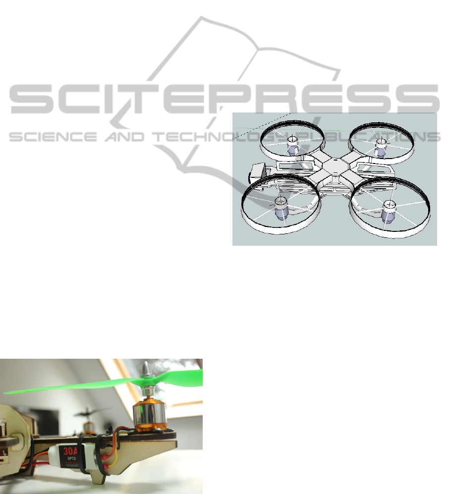
Moreover the camera has to be fixed enough in
the front in a way it won’t film the arms of the
copter with its large camera-angel (fig. 2).
Figure 2: CAD model of the printable copter-frame.
The back of the frame has a specially constructed
box which is adapted to the batteries. The fuselage
and the side parts are constructed to carry the
electric components and connect the protection for
the rotors to each other. The plates are perforated to
lower the air resistance. The rotor-protections with
the cable guide are printed by the RepRap to realize
a good stability with a light weight. It is constructed
with a special curve to offer a landing surface. In
between the bottom there are small grooves to lay
the cables inside for not destroying them by landing
(fig. 3).
The protection for the rotor is guaranteed by a
ring which is fixed at the top and on the bottom with
the fuselage (fig. 3, fig. 4).
All the components were fixed with superglue
and when necessary with cable ties. It is a very
lightweight and quick fixing-method.
The motor should be mounted in the middle of
the ring so the rotor is turning inside the protection.
SmartFabricationofRoboticSystems-AProjectwithUniversityStudents
347
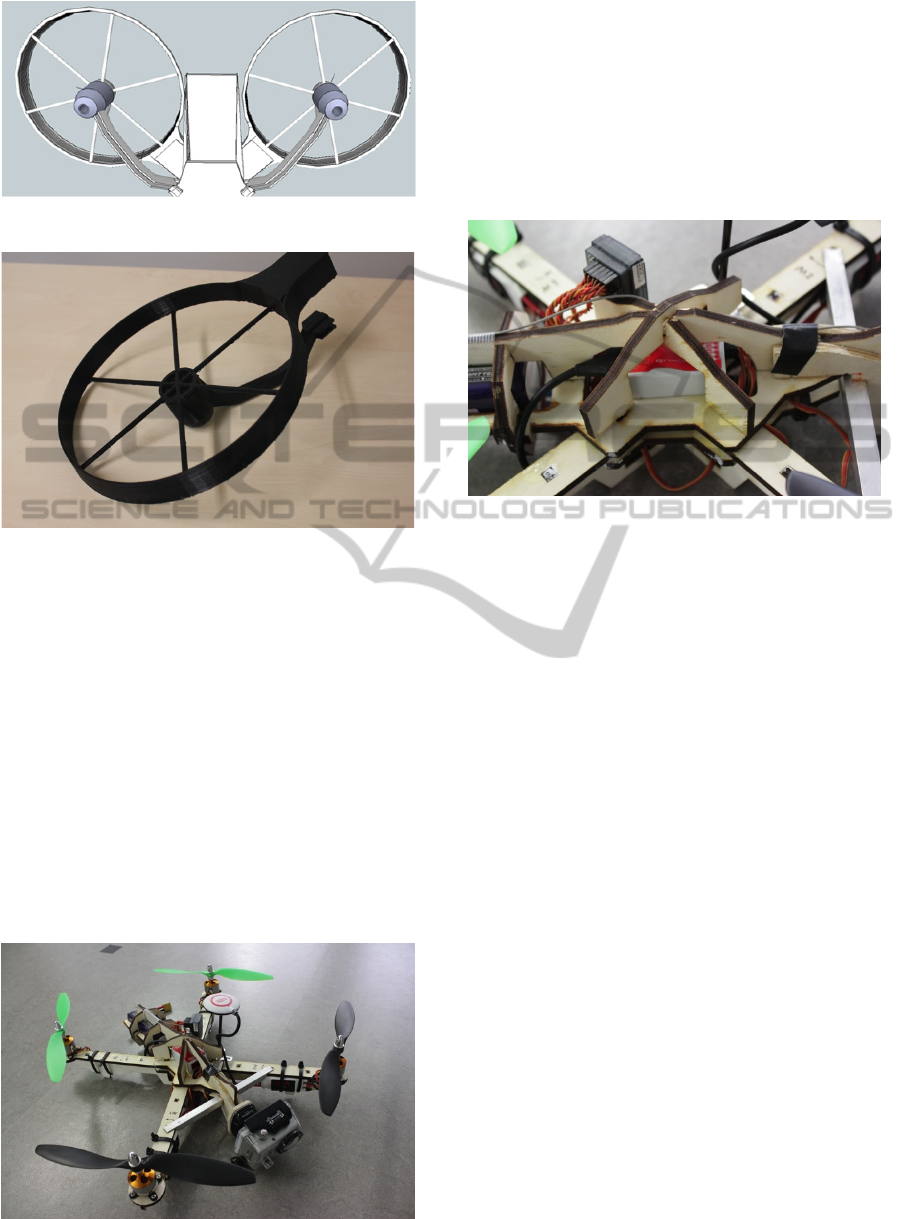
Figure 3: Grooves for cables and rotor-protection.
Figure 4: Printed rotor-protection.
The motor should be mounted in the middle of the
ring so the rotor is turning inside the protection. In
case of a collision the copter will be shaken, but the
rotors aren’t blocked and the copter won’t fall.
Furthermore the ring takes horizontal forces over the
spokes, which don’t increase the air resistance
because of the small size.
The lower parts of the arms support the motor in
vertical direction and provide space to put the cables
in. Also it serves as landing gear.
Other than the printed frame, where the
development-focus was the arms of the copter, for
the plywood frame it isn’t possible to manufacture a
structure as fine as the printed structure. If the rotor-
protection were made by plywood, the spokes can’t
Figure 5: The whole copter made by beech plywood.
take the forces and will break. Because of that it a
simply arm without protection was developed (fig.
5). The focus has been on the fuselage.
As already mentioned in 3.5 there is something
to mind when constructing with plywood. That’s
why there was constructed a plate to put the other
components onto this one first. This way the frame
was getting a ribbed structure and the plug
connection got a better stability (fig. 6).
Figure 6: Ribbed structure.
4.2 GoPro
The very high resolution of the Go Pro Hero 2
provides optimal video quality over radio
communication to the Fat Shark glasses.
Furthermore it is possible to save the videos on a
SD Card at the same time.
The Go Pro is fixed with the supplied camera
holder on a piece of the beech plywood.
(http://www.gopro.com)
4.3 Fat Shark
The Fat Shark realizes a clear picture from the
Camera to the lenses without solar irradiation in a
compact way. Where other lenses with wide-angel-
function fail, the Fat Shark delivers perfect results.
Moreover it is the only one which is upgradeable
with different radio modules and head trackers.
(http://www.fatshark.com)
4.4 Dji
Dji offers reliable products at an affordable price
that are also compatible with many other
components. The installation is very simple and the
safety concept very well.
(http://www.dji-innovations.com)
SENSORNETS2014-InternationalConferenceonSensorNetworks
348

4.4.1 Naza
The Naza Main Controller combines many features.
It is equipped with GPS, air-pressure-sensor as well
as coming-home-function and home lock. It has also
the possibilities to compensate the camera mount.
(http://www.dji-innovations.com)
5 RESULTS
At the beginning the results of the printing-objects
were often gone badly and the material broke. The
nozzles of the extruders were clogged and had been
repaired.
The component size is limited and also the size
of the large, straight printable components in one
piece. This is because the materials deform if it*s
too large and the result isn’t usable.
The printing-objects are resistant to shocks and
impacts and can also survive falls from height. The
way to connect the components between each other
by using superglue proved to be efficient.
Because of the problems with the printed
components, the frame for the finished copter was
fabricated of beech plywood by the CNC-laser-
cutter. The cut out pieces are simple to join together
and after bonding each other there is enough
stability to fly with.
6 DISCUSSION
At the beginning the plan was to build the whole
copter with printed components. The first
components were printed in a good quality, but there
were problems to repeat the printing with this high
quality:
The material breaks because of the incorrect
room-temperature and humidity. By trying we found
out that the indoor temperature must be 23°C and
needs a humidity of 32-48%. Then the material has
an unlimited durability. Unfortunately we couldn’t
keep the conditions all the time. Some components
printed over 24 hours and because of variations in
temperature mainly at night the results were
unusable.
The clogging in the nozzles can be solved by
setting the right temperature in the extruder
according the material parameters.
The deforming of the materials happens because
the temperature difference between nozzles and
printing plate is too high. The material cools down
too fast and the printing cannot continue straight.
This can be resolved by using a heatable-printing-
plate or new software with fine-tuning-modus.
When it is possible to keep the certain conditions
there is a good way to print the whole frame in high
quality.
As a valid alternative to the RepRap-printer the
CNC-Laser-Cutter has been suggested. For the
reason that this machine is independent of external
influences it is easy to produce the same components
again and again in the same quality.
The high stability in addition to a minimal air
resistance is easy to realize with the printer because
the forms are freely selectable. For the cut off pieces
of the CNC-machine it must be aware that plywood
only can absorb forces in longitudinal direction and
fail when forces acting in transverse direction.
That’s the reason why the construction must be in
‘T-form’ (fig. 1).
This art of construction needs a lot of more space
and cannot be realized as slim as the printed model,
which means that the air resistance is higher.
A big disadvantage in contrast to the RepRap is
that the CNC-machine only can produce in 2D,
because there are only exist two axes.
The limited size of printable and cut off
components and the connection with superglue is the
best way to have a strong connection with also
predetermined breaking points. This prevents more
damages and with these breaking points possible
repairs are easier.
7 CONCLUSIONS AND FUTURE
WORK
In conclusion this paper presents a Quadrocopter-
frame built with laser-cut-pieces of beech plywood
and also the research on printing a frame with a
RepRap. Both processes were compared and it was
confirmed that a CNC-laser-cutter is in our case the
better way to create a frame even though it has not
the same possibilities like the printer.
It must be remembered that the 3D-printing-
systems have just started and are still in early stages.
The systems are continually refined and extended so
they will be less sensitive to outside influences. For
printers used by industry it is possible to keep it
away from environmental influences and by time it
will prevail for home-use-printers, too.
The printable copter components are a new way
to build robust and lightweight robotic systems.
In the future there are various possible
SmartFabricationofRoboticSystems-AProjectwithUniversityStudents
349

applications: for example they could be used to
investigate high-rise buildings for cracks, or even to
rescue and recover people in need. Flood victims
who are hard to reach can be powered up to their
rescue with food.
Furthermore this copter already is used “to
monitor environmental data like the current CO
2
value and other measures for air quality in real time”
(Schäfer, M., Jansen, M., Seabra da Rocha, S. F.,
2013).
ACKNOWLEDGEMENTS
Acknowledgements to the HRW to facilitate this
project and to Robert Reichert for spending many
hours to explain us copters.
REFERENCES
Gershenfeld, Neil, 2012 How to Make Almost Anything:
The Digital Fabrication Revolution Foreign Affairs
91, no. 6 (November-December 2012): 43-57.
Kasparova, M., Grafova, L., Dvorak, P., Dostalova, T.,
Prochazka, A., Eliasova, H., Prusa, J., Kakawand, S.,
2013 Possibility of reconstruction of dental plaster
cast from 3D digital study models.
McKinsey & Company, Loc. Cit., 2013 The revival of the
West 21st Century Investment themes, In Perspective.
Jijotiya, Deepika, Dr. Lal Verma, Prap hu, 2013 A survey
of Performance based Advanced Rapid Prototyping
Techniques Scholars Journal of Engineering and
Technologies (SJET).
Simonite, Tom, 2010 I, replicator: Self-replicating
machines comes of age New Scientist, Volume 206,
Issue 2762, 26 May 2010, Pages 40-43.
Hou, M., Ho, G., Arrabito, G.R., Young, S., Yin, S.,
March 2013 Effects of Display Mode and Input
Method for Handheld Control of Micro Aerial
Vehicles for a Reconnaissance Mission IEEE
Transactions on Human-Machine Systems, Vol. 43,
No. 2.
Karl Erik Årzén, 2013 Experiences of a CPS course on
Embedded Control.
Adam Zimmermann, 2012 Starl for Programming
Reliable Robotic Networks.
Technical University of Munich, 2010 Dauerflug-
Weltrekord für Quadrocopter.
Mohd Bijarimi, Sahrim Ahmad, Rozaidi Rasid, 2012
Mechanical, Thermal and Morphological.
Properties of PLA/PP Melt Blends.
Eurapipe, 2013 ABS Material Retrieved from
http://xahax.com/subory/Spec_ABS.pdf.
Schäfer, M., Jansen, M., Seabra da Rocha, S. F., 2013
About Multicopters and Other Smart Devices for
Environmental Monitoring.
SENSORNETS2014-InternationalConferenceonSensorNetworks
350
