
Enhanced Code Generation from UML Composite State Machines
Omar Badreddin
1
, Timothy C. Lethbridge
1
, Andrew Forward
1
, Maged Elaasar
2
,
Hamoud Aljamaan
1
and Miguel A. Garzon
1
1
School of Electrical Engineering and Computer Science, University of Ottawa, Ottawa, Ontario, Canada
2
Department of Systems and Computer Engineering, Carleton University, Ottawa, Ontario, Canada
Keywords: State Machine, Code Generation, Reverse Engineering, Model Oriented Programming, Model Driven
Architecture, Model Driven Development, Umple.
Abstract: UML modelling tools provide poor support for composite state machine code generation. Generated code is
typically complex and large, especially for composite state machines. Existing approaches either do not
handle this case at all or handle it by flattening the composite state machine into a simple one with a combi-
natorial explosion of states, and excessive generated code. This paper presents a new approach that trans-
forms a composite state machine into an equivalent set of simple state machines before code generation.
This avoids the combinatorial explosion and leads to more concise and scalable generated code. We imple-
ment our approach in Umple. We report on a case study, comparing our approach to others in terms of code
size and scalability.
1 INTRODUCTION
State machines are a powerful behavioral modeling
formalism, especially in real time and embedded
systems. Despite being part of UML for many years,
state machines have not played a central role in most
software projects. This may partially be explained
by a survey of modeling practices (Forward et al.
2010) that revealed very poor support for code gen-
eration, in particular for composite (nested) state
machines.
Many tools omit composite state machines en-
tirely, or only generate code for simple state ma-
chines. Others generate excessively complex code or
flatten composite states as a pre-processing step,
resulting in a combinatorial explosion of states. We
will present an approach that overcomes these issues.
Some approaches (Wasowski 2004; Lano et al.,
2007; Niaz and Tanaka 2003) generate code from
composite state machines without the need for flat-
tening. However, these approaches have other
weaknesses; in particular it is important that similar
state machines generate similar code.
Our approach avoids flattening by mapping
composite state machines into an equivalent set of
simple state machines. We present mapping patterns
for possible state machine configurations and
demonstrate these patterns with concrete examples
in Umple (Forward et al., 2010), (Badreddin et al.,
2014), (Badreddin et al., 2014), (Badreddin, 2013),
(Badreddin and Lethbridge, 2013), (Badreddin et al.,
2012), (Badreddin and Lethbridge, 2012).
A live demonstration of the generated code is
available in our online (UmpleOnline, 2013) tool.
In this paper, we first briefly introduce the Um-
ple technology, then present our approach to code
generation of composite state machines. A case
study where we assess our approach and compare it
to other approaches is discussed in section 4. We
show that our approach is more scalable and resulted
in more concise code than the other approaches.
2 OVERVIEW OF UMPLE
Umple extends languages like C++ and Java with
modeling constructs, elevating their level of abstrac-
tion. It supports UML class diagrams, state machines,
and selected software patterns. We present here min-
imal background to allow the reader to understand
Umple code. More information is available else-
where (Lethbridge and Badreddin, 2011; Lethbridge
and Badreddin, 2011; Lethbridge and Mussbacher,
2011; Badreddin, 2010, Lethbridge et al., 2012).
Umple is a fully-functional program-
ming/modeling language. Below is a simple example
235
Badreddin O., Lethbridge T., Forward A., Elaasar M., Aljamaan H. and A. Garzon M..
Enhanced Code Generation from UML Composite State Machines.
DOI: 10.5220/0004699602350245
In Proceedings of the 2nd International Conference on Model-Driven Engineering and Software Development (MODELSWARD-2014), pages 235-245
ISBN: 978-989-758-007-9
Copyright
c
2014 SCITEPRESS (Science and Technology Publications, Lda.)

that defines a state machine model.
01
02
03
04
05
06
07
08
09
10
11
12
13
class Course {
Boolean maxStudentsReached;
courseId;
status {
Open {
[maxStudentReached] register
/{notification();} -> Closed;
Closed {
deRegister/{deRegister();} -> Open;
} }
// placeholder methods
public void notification() { }
p
ublic void deRegister() { } }
Figure 1: Example state machine in Umple.
The Course class has three attributes, maxStuden-
tReached, courseId and status. The status value is
controlled by a state machine with two states, Open
and Closed. When event register() occurs, and if
guard [maxStudentReached] is true, then the transi-
tion action notification() is executed, and status is
updated to Closed. When in Closed state, the state
machine responds to event deRegister(). To save
space above we only provided placeholders for na-
tive code that handles notifications and deregistering.
Umple follows UML semantics with minor de-
viations described in other publications. An example
deviation is that since Umple is textual, the start
state in a state machine is always the first state listed;
there is therefore no ‘start’ pseudostate.
3 CODE GENERATION
FOR COMPOSITE STATE
MACHINES
As in UML specifications, we classify state ma-
chines into simple and composite. Traditional flat-
tening techniques transform a composite state
machine into one simple state machine. This can
result in explosion of the generated code. Our ap-
proach creates a set of simple state machines equiva-
lent to the composite state machine. Our generated
code is significantly smaller in size than that pro-
duced with traditional flattening. Moreover, it is also
smaller to that generated from state-of-the-art mod-
eling tools and research tools reported in the litera-
ture.
3.1 Overview
Umple handles both simple and composite state ma-
chines. After parsing a model and creating an in-
stance of its metamodel (very similar to UML 2.2
metamodel (OMG 2011)), Umple determines
whether each state machine is simple of composite.
For each composite state machine , Umple adds
states, transitions, and actions to transform it into a
set of simple state machines with equivalent behav-
ior. Specifically, a new simple state machine is add-
ed for every nested state machine. Each of these
state machines has a ‘null’ state indicating when it is
inactive, i.e. when some other part of the original
composite state machine is currently active. The
resulting set of state machines is then used to gener-
ate code using the same templates used for simple
state machines.
4 CODE GENERATION CASES
The following sections give a set of patterns for
composite state machines code generation. For ex-
ample, a transition from an outer state to an inner
state in a nested-states environment is one case.
Each of case demonstrates one specific aspect of
composite states. For each case, we show the follow-
ing:
The source UML model
The flattened state machines
Excerpt of the generated code
The equivalent source model in Umple
The algorithm for code generation
The analysis of each case focuses on a specific as-
pect of code generation. Therefore, some questions
may be left unanswered for any given case; these
should become clear in the cases that follow.
Examples are shown in Java, but Umple can also
generate C++ state machines.
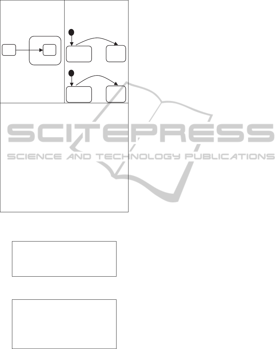
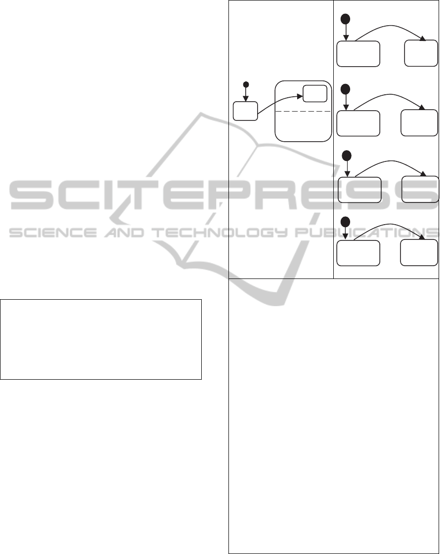
4.1 Case 1: Transition to an Inner State
The first case is a transition to an inner state (Figure
2). The state machine starts in state A. When event
‘e’ occurs, the transition to state C takes place. Since
state C is a substate of B, this is equivalent to transi-
tion from state A to B, and then from state B to C.
Figure 2 shows the source of the composite state
model, the flattened state machines, and the excerpt
of the generated code.
Any exit action(s) from state A are called first,
then transition actions, followed by any entry actions
into B, and finally, entry actions into C.
MODELSWARD2014-InternationalConferenceonModel-DrivenEngineeringandSoftwareDevelopment
236
Equivalent flattened
state machines:
StateMachine
StateMachineB
// Flattened state machines
enum StateMachine { A, B }
enum StateMachineB { Null, C }
// Construction
public ToInnerState(){
setStateMachine(StateMachine.A);
if (stateMachineB == null) { setStateMa-
chineB(StateMachineB.Null); } }
// Event processing
public boolean e(){
boolean wasEventProcessed = false;
switch (stateMachine) {
case A:
setStateMachineB(StateMachineB.C);
wasEventProcessed = true;
b
reak;
}
}
Figure 2: Transition to an inner state.
The Umple model for this example is as follows:
class ToInnerState {
stateMachine {
A { e -> C; }
B {
C {} } } }
For this case only, we show the generated flattened
state machine in Umple syntax.
class ToInnerState {
stateMachine {
A { e -> B ; }
B { } }
stateMachineB {
Null { e -> C ; }
C { } } }
Note that Umple allows multiple state machines to
be declared within the same class. In this example,
the two state machines are stateMachine and state-
MachineB.
For the rest of the cases, we do not show the Umple
model for the flattened state machines for brevity.
The algorithm to achieve this flattening is as follows:
1. Flatten by generating stateMachine and StateMa-
chineB.
2. Set stateMachine to A (the start state)
3. Set stateMachineB to Null (state B is not active)
4. When event e occurs:
- If state A is active, set stateMachineB to state-
MachineB.C
- Return true to indicate the event was processed.
As shown in the diagram and the abstracts of the
generated code, Umple internally creates two state
machines; the first has two states, A and B; the sec-
ond has states Null and C.
Upon construction, the first state machine is up-
dated to state A, and the second state machine is
updated to state Null. State Null is used to indicate
that stateMachineB is not active; i.e., the higher-
level state machine is in some other state than B
(here it is in state A). When event e occurs, two tran-
sitions take place; transition in stateMachine from A
to B, and a transition in StateMachineB from Null to
C. Firing two transitions when a single event occurs
is a feature specific to Umple. This feature is partic-
ularly useful when flattening state machines.
As with simple Umple state machines, the event
handler is generated as a public method. This meth-
od updates the state machine state by calling a pri-
vate method setStateMachineB( ). It encapsulates
calls to any actions and do activities. This encapsula-
tion is important to our code generation approach for
two reasons:
1. It makes all event-processing methods small in
size; they become easier to read and understand.
2. It simplifies the code generation patterns. All
event-processing methods look similar, and can
therefore use the same code generation template.
This event processing method is very simple: it en-
capsulates all method calls when transitioning from
some state to another state. But also, this method
allows for arbitrary complexity in the state machines
the modeler can create; there are an unlimited num-
ber of combinations of source and destination states.
For this reason, we will ignore the complexity of this
method while we are discussing these code genera-
tion cases. The specifics of the code generation for
this method are discussed later in the paper.
4.2 Case 2: Transition from an Inner
State
This case is similar to the previous case except that
Null
B
e
e
A
B
A
B
C
e
EnhancedCodeGenerationfromUMLCompositeStateMachines
237
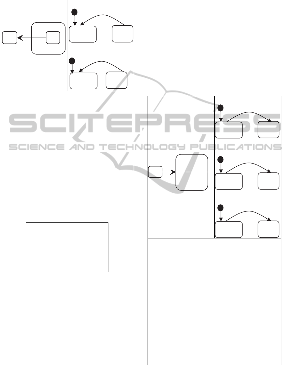
the transition is from an inner state to an outer state.
StateMachine
StateMachineB
// Flattened state machines
enum StateMachine { A, B }
enum StateMachineB { Null, C }
// Construction
public FromInnerState() {
setStateMachineB(StateMachineB.Null);
setStateMachine(StateMachine.A); }
// Event processing
public boolean e() {
boolean wasEventProcessed = false;
switch (stateMachineB) {
case C:
setStateMachine(StateMachine.A);
wasEventProcessed = true;
break; } }
Figure 3: Transition from an inner state.
The Umple model is as follows:
class FromInnerState
{ stateMachine {
A { }
B {
C { e -> A;
} } } }
The flattening algorithm is as follows:
1. Flatten by generating stateMachine and StateMa-
chineB.
2. Set stateMachine to A (the start state)
3. Set stateMachineB to Null (state B is not active)
4. When event e occurs:
- If state C is active, set stateMachineB to Null.
- Set stateMachine to A.
5. Return true to indicate the event was processed.
The code generation for this case is similar to the
previous case, which is an objective we strive to
maintain in Umple; similar state machines should
have similar code generation patterns.
The difference here is in the event-processing
method. In response to the event ‘e’, and if the state
machine is in state C, we update the state machine
state to A. This is also encapsulated in a single
method call setStateMachine( ).
The coming cases entail regions and concurrency.
In our implementation, we consider every region to
be a full-fledged state machine; a region may have
one or more state machine elements of any type,
such as a start state, end states, ordinary states and
transitions. This view of regions allows us to recur-
sively define regions without having to redefine a
new region element. This is similar to a nested state,
where a state can itself contain a state (a substate).
StateMachine
StateMachineC
StateMachineD
/
/ Flattened state machines
e
num StateMachine { A, M }
e
num StateMachineC { Null, C }
e
num StateMachineD { Null, D }
/
/ Construction
p
ublic ToConcurrentState() {
s
etStateMachineC(StateMachineC.Null);
s
etStateMachineD(StateMachineD.Null);
setStateMachine(StateMachine.A); }
/
/ Event prcoessing
p
ublic boolean e() {
boolean wasEventProcessed = false;
switch (stateMachine) {
case A:
setStateMachine(StateMachine.M);
wasEventProcessed = true;
break; }
return wasEventProcessed; }
Figure 4: Transition to a concurrent state.
Null
D
e
Null
C
e
e
A
M
A
M
C
D
e
Null
C
e
e
A
B
A
B
C
e
MODELSWARD2014-InternationalConferenceonModel-DrivenEngineeringandSoftwareDevelopment
238
4.3 Case 3: Transition to a Concurrent
State
In this case, the state machine starts in state A.
When the event ‘e’ occurs, the transition from state
A to the composite state M takes place. Instantane-
ously, the two regions C and D become active.
Umple creates internally three state machines;
StateMachine that has two states, A and M; State-
MachineC that has two states, null and C; and finally
StateMachineD that has two states null and D.
We use the dummy state null in a consistent
manner. If a state machine is in state null, it means
that the state machine is not active. In this case, if
the state machine is in state A, then both regions C
and D are set to Null.
The Umple model for this example is as follows:
class ToConcurrentState {
stateMachine {
A { e -> M; }
M { C {}
| |
D {} } } }
The flattening algorithm for this case is as follows:
1. Flatten by generating stateMachine and StateMa-
chineC and stateMachineD.
2. Set stateMachine to A (the start state)
3. Set stateMachineC to Null.
4. Set stateMachineD to Null.
5. When event e occurs:
- Set stateMachine to M.
- Set stateMachineC to C
- Set stateMachineD to D
6. Return true to indicate the event was processed.
At construction, the state machine is set to state
A. The two other state machines (statemachineC and
statemachineD) are set to state null. When event ‘e’
occurs, the state machine becomes in state M. The
method setStateMachine(stateMachine.M) updates
the states for the two regions C and D and calls entry
and exit actions, if any. Notice the level of similarity
between event processing methods in the previous
cases, even though the transition is of a different
nature. This similarity was achieved by means of
hiding the transition details in a single method call.
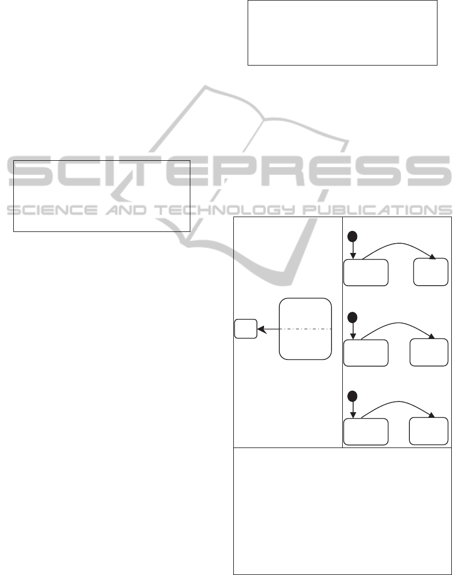
4.4 Case 4: Transition
from a Concurrent State
This case occurs when a transition out of a compo-
site state takes place. In this example, the state ma-
chine starts in state M, which has two concurrent
regions, C and D. Event ‘e’ triggers a transition out
of the composite state.
The Umple model for this example is as follows:
class FromConcurrentState {
stateMachine {
M { e -> A;
C {}
||
D {} }
A
{} } }
The flattening algorithm is as follows:
1. Flatten by generating stateMachine and State-
MachineC and stateMachineD.
2. Set stateMachine to M (the start state)
3. Set stateMachineC to C.
4. Set stateMachineD to D.
5. When event e occurs:
- Set stateMachine to A.
- Set stateMachineC to Null
- Set stateMachineD to Null.
6. Return true to indicate the event was processed.
StateMachine
StateMachineC
StateMachineD
/
/ exiting a composite state
public boolean exitM() {
boolean wasEventProcessed = false;
switch (stateMachineC) {
case C:
setStateMachineC(StateMachineC.Null);
wasEventProcessed = true;
break; }
switch (stateMachineD) {
c
ase D:
s
etStateMachineD(StateMachineD.Null);
wasEventProcessed = true;
b
reak; } }
Figure 5: Transition from a concurrent state.
D
Null
e
C
Null
e
e
M
A
A
M
C
D
e
EnhancedCodeGenerationfromUMLCompositeStateMachines
239
When exiting a simple state, a single switch state-
ment suffices. A concurrent state with two regions
requires two switch statements. The first switch
statement checks if region C is active, and if so, up-
dates the state machine to null using the method
setStateMachineC, which also handles any exit ac-
tions. The second switch statement performs the
same steps for region D.
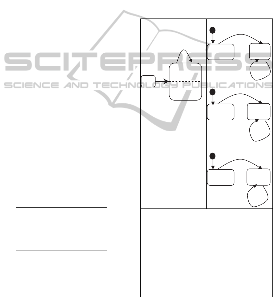
4.5 Case 5: Reflexive Transition
of a Concurrent State
This case focuses on the implementation of a reflex-
ive transition. A reflexive transition is just another
transition whose source state and destination state
are the same. A reflexive transition of a composite
state with two concurrent regions behaves as follows:
1. Call exit actions associated with any state being
exited, including the composite state itself. Start-
ing with the innermost state and working your
way outward.
3. Exit all regions of the concurrent state;
4. Call transition actions, if any;
5. Re-enter the concurrent state;
6. Re-enter each concurrent region;
7. Call entry actions of any state being entered in-
cluding the composite state itself.
According to state machine semantics, exiting
the two regions takes place at the same time. How-
ever, if you are executing the state machine in a sin-
gle-threaded environment, one region will be exited
before the other. Due to the sequential nature of
Umple, the region that is declared first is exited first.
To override such behavior, one can re-order the re-
gions so that region D is declared before region C.
The same applies for entering a concurrent region in
step 5 above.
The Umple model for this example is as follows:
class Reflexive {
stateMachine {
A { e -> M; }
M { e -> M;
C {}
|| D {} } } }
The flattening algorithm is as follows:
1. Flatten by generating stateMachine and State-
MachineC and stateMachineD.
2. Set stateMachine to A (the start state)
3. Set stateMachineC to Null.
4. Set stateMachineD to Null.
5. When event e occurs:
- Set stateMachine to M, set stateMachineC to C,
and set stateMachineD to D.
6. When event e occurs (triggering the reflexive
transition):
- Call exitStateMachine() method, which exits all
regions of M and exits M itself.
- Set stateMachine to M (re-entering composite
state)
- Set stateMachineC to C
- Set stateMachineD to D.
7. Return true to indicate the event was processed.
StateMachine
StateMachineC
StateMachineD
/
/ Reflexive transition
p
ublic boolean e() {
boolean wasEventProcessed = false;
switch (stateMachine) {
case A:
setStateMachine(StateMachine.M);
wasEventProcessed = true;
break;
case M:
exitStateMachine();
setStateMachine(StateMachine.M);
wasEventProcessed = true;
break; }
return wasEventProcessed; }
Figure 6: Reflexive transition of a concurrent state.
Null
D
e
e
e
Null
C
e
e
A
M
e
e
A
M
C
D
e
MODELSWARD2014-InternationalConferenceonModel-DrivenEngineeringandSoftwareDevelopment
240
Note the switch statement in the generated code.
The first case handles the behavior when the state
machine is in state A. The second case handles when
the state machine is in state M. Our focus here is on
the second case. The following takes place:
1. Calling the method exitStateMachine( ) which en-
capsulates the logistics of exiting all regions.
2. Re-entering the state M by calling the method
setStateMachine(StateMachine.M( )
3. Updating the Boolean variable to indicate that the
event was processed
4.6 Case 6: Transition into an Inner
State in a Concurrent Region
This case explores a scenario when a transition to an
inner state which lies inside a concurrent region.
This case is special because even though the transi-
tion explicitly enters one region, the second region
must also be activated. In our example below, the
state machine is initially in state A. When the event
‘e’ occurs, the state machine instantaneously enters
the concurrent state M and also instantaneously en-
ters state E. In that situation, the state machine is in
state M, and in state E. Both regions C and D are
active.
The Umple model for this example is as follows:
class ToConcurrentState {
stateMachine {
A { e -> E; }
M { C {
E {entry/{inside_E;} } }
||
D {} } } }
The flattening algorithm is as follows:
1. Flatten by generating stateMachine StateMa-
chineC,stateMachineCC, and stateMachineD.
2. Set stateMachine to A (the start state)
3. Set stateMachineC to Null.
4. SetStateMachineCC to Null.
5. Set stateMachineD to Null.
6. When event e occurs:
- Set stateMachine to M.
- Set stateMachineC to C.
- Set stateMachineCC to E.
- Set stateMachineD to D.
7. Return true to indicate the event was processed.
This case results in four internal state machines as
shown in the generated code above. Notice how the
event processing method is similar to other cases.
This is because the public method ‘e’ delegates to
the method setStateMachineCC that calls the entry
action and updates the state machine state.
StateMachine
StateMachineC
StateMachineCC
StateMachineD
// Flattened state machines
enum StateMachine { A, M }
enum StateMachineC { Null, C }
enum StateMachineCC { Null, E }
enum StateMachineD { Null, D }
// Event processing
public boolean e() {
boolean wasEventProcessed = false;
switch (stateMachine) {
case A:
setStateMachineCC(StateMachineCC.E);
wasEventProcessed = true;
break; }
return wasEventProcessed; }
private void
setStateMachineCC(StateMachineCC
aStateMachineCC) {
stateMachineCC = aStateMachineCC;
if (stateMachineC != StateMachineC.C
&& aStateMachineCC !=
StateMachineCC.Null)
{ setStateMachineC(StateMachineC.C); }
// entry action
switch(stateMachineCC) {
case E:
inside_E;
break; } } }
Figure 7: Transition into inner state in a concurrent region.
Null
D
e
Null
C
e
e
A
M
e
A
M
C
D
E
Null
E
e
EnhancedCodeGenerationfromUMLCompositeStateMachines
241

4.7 State Transition Method
As we have demonstrated in the code generation
cases, there are many variations of state transitions.
The following are the characteristics of such varia-
tions: 1) Is the source state a simple state or compo-
site state? 2) Is the source state is composite, is it
nested or concurrent? 3)Are there any states being
exited that have exit actions associated with them? 4)
Does the transition have any transition action associ-
ated with it? 5) Is the destination state a simple state
or a composite state? 6) Are there any entry actions
associated with any state being entered?
The answers to these questions demonstrate
some of the complexities of implementing transi-
tions that are typically transferred to the generated
code.
Our objective is to generate simple and concise
code; simpler code generation is also easier to im-
plement. If we are able to make event-processing
methods look similar, we will be able to use simpler
code generation templates to implement them.
We achieved this by abstracting common pro-
cessing elements in an event processing method and
encapsulating the details in other internal methods.
To demonstrate the complexity of implementing
a transition, and how Umple handles this complexity,
we will reuse two of the cases presented earlier in
this paper. For this analysis, we assume that all tran-
sitions have both a guard G and an action A associ-
ated with them. We also assume that every state has
an entry and exit action.
4.8 Entering a Composite State
This analysis is based on a modified state machine in
case 3 above. The equivalent model represented us-
ing Umple notation is below. For those not familiar
with Umple syntax, the model here is identical to
case 3 model, but adds entry actions in state M, C,
and state D. The model here also adds a guard and
an action to the transition from A to M.
class ToConcurrentState {
stateMachine {
A { e [g] ->/{transition_action();}M;}
M { entry/ {entering_M;}
C { cState {entry/ {entering_C();} } }
||
D { dState {entry/ {entering_D();} } }
} } }
Figure 8: Entering a composite state.
The code that implements the transition from A to M
is presented in the following four steps.
Step1: Public Function to handle the Event Pro-
cessing.
public boolean e() {
boolean wasEventProcessed = false;
switch (stateMachine){
case A:
if (G) {
transition_action;
setStateMachine(StateMachine.M);
wasEventProcessed = true; }
break; }
return wasEventProcessed; }
Figure 9: Step 1.
The public method is named after the event name. In
this case, ‘e’. This method returns a Boolean indicat-
ing whether the event has been processed or not.
Checking for the guard takes place within this meth-
od (as highlighted above). The method also calls the
transition action right after checking for the value of
the guard. The method then delegates the rest of the
transition execution to setStateMa-
chine(StateMachine.M).
Step 2: setStateMachine.
private void setStateMachine(StateMachine aState-
Machine) {
stateMachine = aStateMachine;
// entry actions
switch(stateMachine) {
case M:
entering_M;
if (stateMachineC == StateMachineC.Null) {
setStateMachineC(StateMachineC.C); }
if (stateMachineD == StateMachineD.Null) {
setStateMachineD(StateMachineD.D); }
break; } }
Figure 10: Step 2.
This method will call any entry actions. In this case,
entering_M is called. The entry action is called prior
to updating the state machine configurations (i.e
prior to updating the state machine attributes).
Therefore, if the entry action queries the state ma-
chine, an inaccurate value would be returned.
Initially, both regions’ states are set to null. This
method checks if the region is in the null state, and if
so, it will delegate to setStateMachineC and
setStateMachineD respectively. For brevity, we only
analyze setStateMachineC.
MODELSWARD2014-InternationalConferenceonModel-DrivenEngineeringandSoftwareDevelopment
242

Step 3: setStateMachineC.
private void setStateMachineC(StateMachineC
aStateMachineC) {
stateMachineC = aStateMachineC;
if (stateMachine != StateMachine.M &&
aStateMachineC != StateMachineC.Null)
{ setStateMachine(StateMachine.M); }
switch(stateMachineC) {
case C:
if (stateMachineCC == StateMachineCC.Null)
{setStateMachineCC(StateMachineCC.cState);}
break; } } }
Figure 11: Step 3.
This method would call any entry actions. In this
case, there are no entry actions associated with the
stateMachineC. The method updates the state ma-
chine state to cState by means of delegation to
StateMachineCC.cState.
Step 4: setStateMachineCC.
private void setStateMachineCC(StateMachineCC
aStateMachineCC) {
// entry actions
switch(stateMachineCC) {
case cState:
entering_C;
break; } } }
Figure 12: Step 4.
This method finally calls the entry action for the
cState.
4.9 Exiting a Composite State
The steps for exiting a composite state machine are
very similar to entering a composite state machine.
Again, this similarity makes it easier to follow the
generated code, and makes the code generation tem-
plates less complex and easily extendable. For brevi-
ty, we show the method for exiting the composite
state M.
public boolean exitM() {
boolean wasEventProcessed = false;
switch (stateMachineC) {
case C:
exitStateMachineC();
setStateMachineC(StateMachineC.Null);
wasEventProcessed = true;
break; }
switch (stateMachineD) { .. } }
Figure 13: Exiting the composite state.
When exiting the composite state M, we also exit
stateMachineC and stateMachineD. For brevity, we
analyze the steps for exiting stateMa-chineC. Again,
we delegate to exitStateMachineC for the handling
of exit actions, if any, and for updating the state ma-
chine state. Notice that when we exit the state ma-
chine, we set its state to null.
5 COMPARISON
OF APPROACHES
In this section, we compare Umple’s code genera-
tion approach to that of a commercial tool (Rhapso-
dy) and a research tool whose authors (Niaz et al.,)
claim a novel approach of generating efficient and
compact code for composite states (Niaz et al.,
2003).
Rhapsody implements state machines using mul-
tiple classes and creates objects that represent states
up-front; i.e, as soon as the state machine becomes
active. These objects stay in memory as long as the
state machine is executing. Rhapsody uses a switch
statement and a helper class to implement the state
machine behavior.
The research tool proposed by Niaz also uses
multiple classes, where each state is implemented in
a separate class. However, objects are not created
up-front; rather, objects are created and deleted at
run time. This makes the expected performance of
this tool potentially better than Rhapsody. Niaz’s
approach implements composite state machines by
using object composition and delegation. In our
comparison, we adopt criteria identical to Niaz’s
(Niaz et al., 2003) that base comparison on number
of lines of code, bytes, and classes. For the base
comparison, we consider the example in Figure 14.
In many cases, we were unable to compare our
approach to other tools due to the fact that such tools
typically do not support composite states in a way
complete enough to allow for this comparison. For
example, Bridgepoint (Mentor Graphics, 2012) does
not allow substates or guards.
Figure 14: Composite state comparison example.
Lines of code, despite its simplicity, is arguably
the most effective measure for complexity (Gold et
EnhancedCodeGenerationfromUMLCompositeStateMachines
243

al., 2005). It is also reported that cyclomatic com-
plexity tends to be comparable to lines of code when
measuring complexity (Gill and Kemerer, 1991).
Table 1: Code generation comparison.
Rhapsody Niaz Umple
generated
Code
Umple
LOC
675 250 125 8
Bytes
24,270 6,420 5,010 197
Classes
7 11 1 1
As shown, the number of lines of code is significant-
ly lower in the case of Umple (a reduction of about
50% as compared with Niaz`s approach). The num-
ber of bytes is less in the case of Umple (a reduction
of about 22%).
This comparison cannot be a final word on gen-
erated code complexity. Other complexity measures
may give different results. In addition, It is possible
that Rhapsody or Niaz’s tool provide additional gen-
erated code to support functionality not available in
Umple. The generated code that was used in Niaz’s
study was not publicly available for inspection. On
the other hand, all of our examples can be compiled
and the code generated online. Making our algo-
rithm and its implementation available for future
research.
6 CONCLUSIONS
This paper presented an approach for code genera-
tion from composite state machines. We generate a
set of state machines equivalent to the original state
machine, and use ‘null’ states to indicate when any
given state machine is not active.
We presented cases covering each possible con-
figuration of composite states and their transitions.
Each case exposes an aspect of the code generation.
Our approach significantly reduces complexity and
code volume.
We have also introduced a unique concept in the
Umple model-oriented language where multiple
state machines can reside in the same class and
where multiple transitions can be fired by a single
event.
The code generation method and the associated
algorithms are implemented and are fully available
for inspection online.
REFERENCES
Badreddin O., Lethbridge T. C. and Elassar M., 2013.
"Modeling Practices in Open Source Software." Open
Source Software: Quality Verification. Springer. 127-
139.
Badreddin O., 2010. "Umple: A Model-Oriented Pro-
gramming Language," in Proceedings of the 32nd
ACM/IEEE International Conference on Software En-
gineering,Vol. 2, pp. 337-338.
Badreddin O., Forward A. and Lethbridge T.C., 2012.
"Model oriented programming: an empirical study of
comprehension." 2012 Conference of the Center for
Advanced Studies on Collaborative Research. IBM
Corp.
Badreddin O., Forward A., and Lethbridge T. C., 2014.
"Exploring a Model-Oriented and Executable Syntax
for UML Attributes." Software Engineering Re-search,
Management and Applications. Springer, 33-53.
Badreddin O., Forward A., and Lethbridge T. C., 2014.
"Improving Code Generation for Associations: En-
forcing Multiplicity Constraints and Ensuring Refer-
ential Integrity." Software Engineering Research,
Management and Applications. Springer, 129-149.
Badreddin O., Lethbridge T. C., 2013. “Model Oriented
Programming: Bridging the Code-Model Divide”.
ICSE Workshop on Modeling in Software Engineering
(MiSE), 2013 5th International Workshop,
10.1109/MiSE.2013.6595299. Pages: 69 - 75.
Badreddin O., Lethbridge T. C., Lethbridge T. C., 2012.
"Combining experiments and grounded theory to eval-
uate a research prototype: Lessons from the umple
model-oriented programming technology", User Eval-
uation for Software Engineering Researchers (USER),
2012. 10.1109/USER.2012.6226575. Page(s): 1- 4.
Badreddin O.,2013. "Empirical evaluation of research
proto-types at variable stages of maturity", User Eval-
uations for Software Engineering Researchers (USER),
2013 2nd International Workshop, 10.1109/
USER.2013.6603076. Pages: 1- 4.
Forward A., Badreddin O., Lethbridge T.C.,. "Perceptions
of Software Modeling: A Survey of Software Practi-
tioners," in 5th Workshop from Code Centric to Model
Centric: Evaluating the Effectiveness of MDD
(C2M:EEMDD), 2010. Available: www.esi.es/
modelplex/c2m/papers.php.
Gill G.K., Kemerer C.F., 1991. “Cyclomatic complexity
density and software maintenance productivity”, IEEE
Transactions on Software Engineering, 17(12).
Gold N. E., Mohan A. M., Layzell P. J., 2005. “Spatial
complexity metrics: an investigation of utility”, IEEE
Trans. on Software Engineering,.31(3), pp. 203-212.
Lano K., Clark D., 2007. "Direct Semantics of Extended
State Machines". TOOLS’07, pp. 35-51.
Lethbridge T.C., Badreddin O., 2011. "Umple - Associa-
tions and Generalizations". Accessed 2012,
http://www.youtube.com/watch?v=HIBo0ErCVtU.
Lethbridge T. C., Badreddin O., 2011. "Umple - State
Machines Details". http://www. Youtube. com/
watch?v=mFczzVkTZ9g.
MODELSWARD2014-InternationalConferenceonModel-DrivenEngineeringandSoftwareDevelopment
244

Lethbridge T. C., Mussbacher G., Forward A. and Ba-
dreddin O., 2011. "Teaching UML using Umple: Ap-
plying Model-Oriented Programming in the
Classroom", CSEE&T, pp. 421-428.
Lethbridge T. C., Forward A., Badreddin O., 2010. "Um-
plification: Refactoring to Incrementally Add Abstrac-
tion to a Program," in Working Conf. on Reverse Eng,
pp. 220-224.
Lethbridge T. C., Forward A., Badreddin O., 2012. "Um-
ple Google Code Project". Available:
http://code.umple. org.
Mentor Graphics Corporation, 2010. "Mentor Graphics
Bridge-Point", accessed 2012, http://www.mentor.
com/products/sm/model_development/bridgepoint/.
Niaz I. A., Tanaka I. A., 2003. "Code Generation from
UML Statecharts" in Proc. 7 Th IASTED International
Conf. on Software Engineering and Application (SEA
2003). pp. 315-321.
OMG, 2010. "UML Specifications", accessed 2011,
http://www.omg.org/spec/UML/.
Schaumont P.R., 2010. A Practical Introduction to hard-
ware/software Codesign. Springer Verlag.
UmpleOnline, 2013. "Umple Online", accessed 2013,
http://try.umple.org.
Wagner F., Wolstenholme P., 2004. "Misunderstandings
about State Machines". Computing and Control Eng,
vol 15, pp. 40-45.
Wasowski A., 2004. "Flattening State Machines without
Explosions", ACM Sigplan Notices, vol 39, ACM.
257-266.
EnhancedCodeGenerationfromUMLCompositeStateMachines
245
