
Neural Networks Controler of a Lower Limbs Robotic Rehabilitation
Chair
M. A. Mamou and N. Saadia
Institute of Electronic, USTHB University, Bab-Ezzouar, Algiers, Algeria
Keywords: Feed Forward Neural Network, PID Controler, Kinematic Model, Path Tracking, Rehabilitation Robot,
Lower Limbs.
Abstract: In this paper, we propose a new control law using a kinematic model based on a Feed forward neural
network (FFNN). This controller is designed for the control of a robotic rehabilitation chair of the lower
limbs designed and created in the LRPE laboratory, with high accuracy. The results of the validation tests,
show that the lower limb joints trajectories of the proposed control law are similar to the physiological joints
trajectories of a patient. This demonstrates that the proposed control law provides a high performance and a
fast convergence with extremely low error.
1 INTRODUCTION
Robotic devices find a growing interest in their use
to assist in providing therapy rehabilitation
following neurological injuries such as spinal cord
injury, stroke and after a joint and / or muscle
traumas (Reinkensmeyer, 2004; Riener, 2005).
Many rehabilitation devices of human limbs and
joints are the subject of study by researchers to assist
therapists and patients. In this context, we developed
in the LRPE laboratory a rehabilitation prototype of
lower limbs. The device is a robotic chair for
neuromatrix rehabilitation of lower limb with two
motorized orthotics (right and left leg), with 3DOF
for each of them (hip, knee and ankle). Position
sensors are mounted on each link to manage the flow
of a predetermined motion in real time.
We find in literature different strategies to
control the path to follow for robotic rehabilitation.
For the upper limbs, (Lo, 2012) reviews the control
strategies, among the control structures, devices
using PID (Moughamir, 05), others use either fuzzy
or neuro-fuzzy logic (Zeinali, 2010; Rahman, 2006).
However, for lower limb, there are not many works
addressing control strategy to control desired
trajectories. Schmitt & Métrailler used to control
Motion Maker in (Schmitt, 2004) an intelligent
central unit "Control unit", called Industrial PC,
composed of different modules; (Seddiki, 2006)
proposed three control laws for a SOKINETICS’s
good trajectory tracking, two with a PI and a third
fuzzy H-infinite hybrid control. Fuzzy logic has
been used in (Akdogan, 2011). The control in,
(Anama, 2012) is done with a PID. Meanwhile, they
used a hierarchical control with PD, even modified
genetic algorithms have been used (Jamwal, 2009).
Therefore, we conclude that the use of neural
networks for system control of the lower limbs is not
common.
Our work consists of controlling the trajectory of
a rehabilitation system of lower limbs (robotic
rehabilitation chair, and the originality lies in the
fact that we us the kinematic model of the robotic
rehabilitation chair based on neural networks {Feed
forward neural network (FFNN)}. In this approach a
PID controller is used offline to train the FFNN.
This results in better online results than when using
traditional PID controllers.
The outline of this paper is as follows: First, we
present the rehabilitation system developed in the
LRPE laboratory for which we establish the
geometric and kinematic model before proposing its
control law. Then, we present the control system
used for parameters identification based on a
conventional PID and the new scheme using a neural
controller (feed forward neural network (FFNN)).
After that, we present the implementation of the
controller on the system. Finally, a discussion of the
results and conclusions are presented.
65
A. Mamou M. and Saadia N..
Neural Networks Controler of a Lower Limbs Robotic Rehabilitation Chair.
DOI: 10.5220/0004700700650071
In Proceedings of the International Conference on Biomedical Electronics and Devices (BIODEVICES-2014), pages 65-71
ISBN: 978-989-758-013-0
Copyright
c
2014 SCITEPRESS (Science and Technology Publications, Lda.)
2 SYSTEM DESCRIPTION
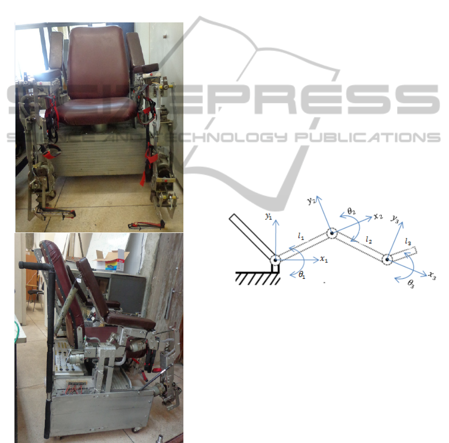
The prototype dedicated to the rehabilitation of
lower limbs for patients with motor deficiencies
developed in our laboratory is shown in (figure-1).
The main use of this prototype is to provide
functional rehabilitation of the lower limbs using
functional orthotics. The implemented system allows
the reproduction of physiological joints trajectories
and take back segmental loads of body movements,
especially walking.
Figure 1: Lower limbs rehabilitation chair robot.
The robotic rehabilitation chair is made up of
two orthosis and a seat mounted on a frame. Both
mechanical orthotics, are placed on either side of the
seat. Each orthotic, which can operate around three
degrees of freedom, consists of three joints: hip,
knee and ankle and three segments: thigh, leg and
foot. Joints ensure transmission of movement
between the different segments taking into account
the factor of safety, the patient’s weight and waist
using a mechanism consisting of rods, gears and DC
motors (Merrouche, 2011; Saadia, 2009).
3 SYSTEM MODEL
In order to create the geometric model of the system,
we usual introduce a fixed coordinate system
(frame) in which all objects is referenced. In our
approach, we establish the basic coordinate system
with chair’s frame, represented by Ox
1
y
1
, as shown
in Figure 2. The coordinates of the point are given
according to the plan Ox
2
y
2
which Ox
2
superimposed on l
1
. In the same way, the
coordinates of the last point are given on the plan
Ox
3
y
3
where Ox
3
is superimposed on l
2
.The tool’s
coordinates are expressed in this coordinate system
(Spong, 2005; Fu, 1987). l
1
, l
2
and l
3
represent the
length of each segment,
is the angle between Ox
i
and l
i
.
Figure 2: Three link Coordinate system of the chair’s
frame.
The direct geometric model (DGM) of the system is
represented by the relation
(1)
Where is the vector of joint coordinates such as :
T
(2)
The vector is defined by the elements of the
homogeneous transformation matrix
α
A
β
(Khalil,
2010; Dombre, 2007). This matrix (
α
A
β
) gives the
coordinate frame R
β
from those of frame R
α
:
BIODEVICES2014-InternationalConferenceonBiomedicalElectronicsandDevices
66
0
0
0
00
00
10
01
3
1
0
0
00
00
10
01
4
2
0
0
00
00
10
01
5
,
and
are the lengths corresponding to the
thigh, leg and foot. They can be manually adjusted.
In our test, we choose respectively the values 50, 60
and 25 cm.
We calculate the
0
A
3
matrix which leads to the
coordinate frame R
3
from those of frame R
0
0
0
∗
1
∗
2
0
0
0
0 0
0 0
1 0
0 1
6
Where:
cos
;
;
cos
;
;
cos
;
;
3.1 Kinematic Model
The direct kinematic model (DKM) is given by
(Jazar, 2010; Khalil, 2004):
xtJ
θ
∗
θ
t
(7)
Where J(θ) denotes the (i x j) Jacobian matrix. The
élément «J_ij (θ) » is given by equation (8):
J
θ
δ
f
θ
θ
(8)
The inverse kinematic model (IKM) is calculated
from the inverse matrix J
-1
according to the
mathematical formulas, the model equation is:
θ
tJ
θ
∗xt
(9)
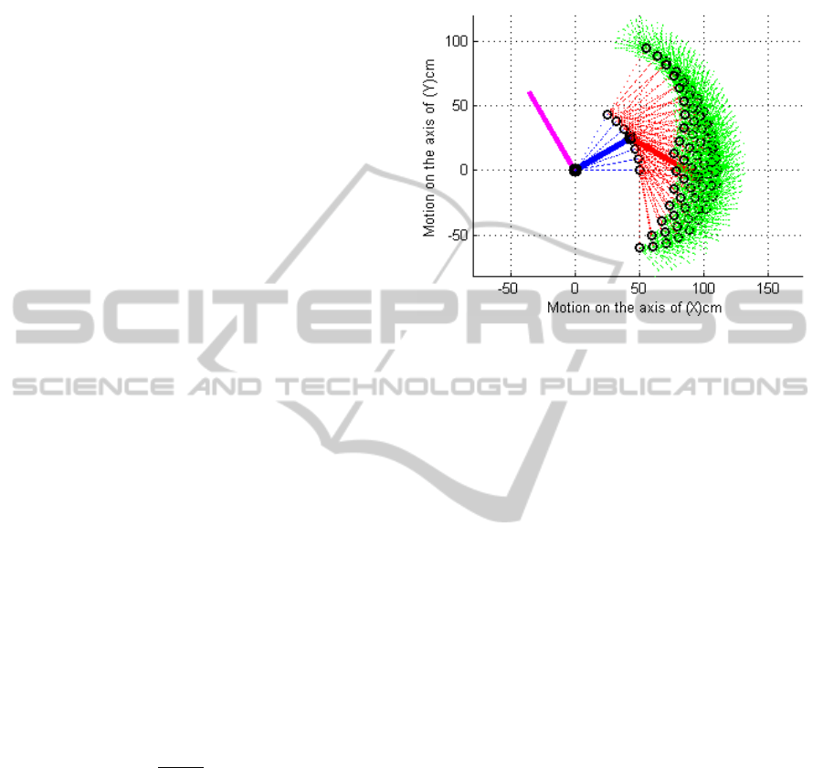
The workspace and manipulability are based on
kinematics criteria often used for robot architecture
selection (Bhangale, 2004). The workspace for one
orthesis of the lower limbs robotic rehabilitation
chair is illustrated in figure-3. This figure shows all
the possible position configurations during the
movement of the joint depending on the previous
one; they are represented by discontinuous lines. As
an example we took a configuration that we have
shown with continuous lines.
Figure 3: One orthesis Workspace.
4 THE CONTROL STRATEGY
In order to control this system, we propose a control
structure using a kinematic model of the robotic
rehabilitation chair based on neural networks (Feed
Forward Neural Network (FFNN)). The control law
is implemented in two steps, the first one is an
offline phase and consists of training the FFNN and
the second law is performed online in order to adjust
the parameters of the FFNN to get the best
parameters of the control structure connected to the
learning.
Given that the two orthesis are identical, they are
represented with the same model equations. For
simplicity reasons, we will command only the right
orthotic. In addition, we use a decoupled architecture
where each joint is controlled separately. Therefore,
we will have three identical control schemes for
each orthotic. The control schemes are illustrated in
(figure 4 -5).
In the first step, to perform the learning
process, we choose to use a PID
controller.
The FFNN controller is trained off-line
through a classical control (PID) law (Figure-
4). The PID is used to identify and provide
the required training data. To train the
FFNNC we use the backpropagation
algorithms.
NeuralNetworksControlerofaLowerLimbsRoboticRehabilitationChair
67
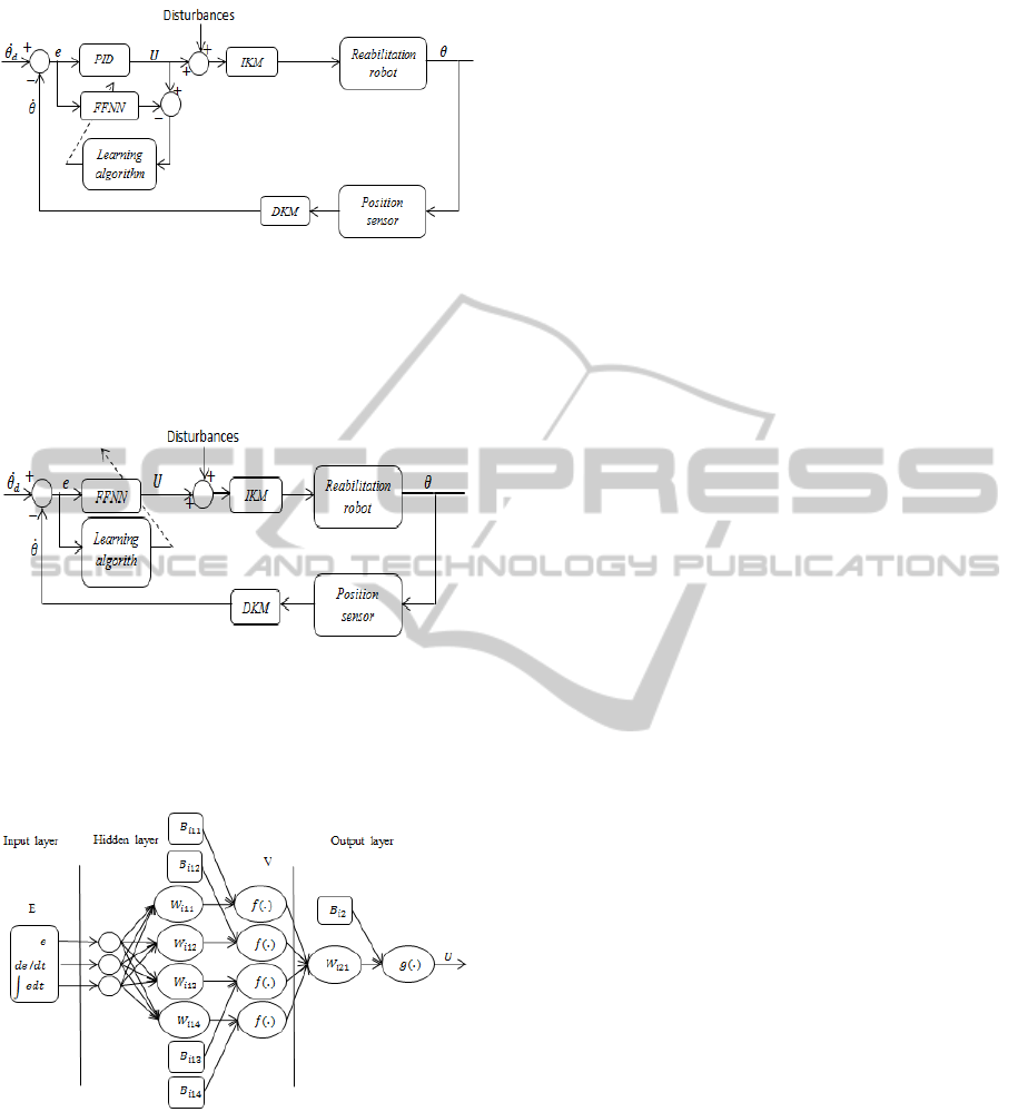
Figure 4: Parameters identification of the control law
structure.
In the second step an online adaptation of the
neural controller to regulate its parameters
according to the task performed is used
(Figure-5).
Figure 5: Real time control law Structure.
The figure below represents the architecture used in
the FFNN. It is composed of three layers. The input
layer consists of three neurons, the hidden layer of
four neurons, and the output layer of one neuron.
Figure 6: Neural network Structure.
The input "E" and output "U" represent the error and
the control vectors respectively. The matrix output
« V » of the hidden layer and the output « U » of the
network are given by:
(10)
(11)
Where (
,
) and (
,
) are the weights and
bias matrices of respectively to adjust. And
0,…,3 number of joints. .and
.
are the
activation function of the neurons in hidden and
output layer. These functions are choose as
sinusoidal for the hidden layer, and as linear for the
neurons of the output layer.
The proposed control law, according to the
equations (12) (Khalil, 2004; Corke, 2011), allows
the matching of error values (Δθ) and the signal
control given by:
(12)
Where:
θ
and θ
are the desired and measured values.
C is the control law.
U is the signal control
Implementation of this control law requires steps
mentioned above and illustrated in ( Figure-4 & 5).
5 IMPLEMENTATION AND
TESTS
To validate the command structure that we have
established, we must make the implementation of
the lower limbs robotic rehabilitation chair by
generating a specified path of the rehabilitation. This
trajectory is a challenge that is the subject of
discussion within the scientific community. Marchal
has made a detailed study that includes several
works on this subject (Marchal-Crespo, 2009). In
this article, we simulate joints trajectory by
generating sinusoidal signals because they are
similar to physiological movements (flexion –
extension). Indeed, it is important to test the
controller with a signal that is as natural as possible
for even of the system behavior. The signal is within
the operating range of the rehabilitation robot.
The architecture of the neural networks used is
made of three layers. The input layer has three
neurons; the hidden layer has four neurons and the
output layer has one neurons.
For the learning function algorithm of the FFNN,
we use the « trainlm » function from the MATLAB
toolbox. Indeed, the network learning function
updates weight and bias values according to the
Levenberg-Marquardt optimization scheme.
« trainlm » is often the fastest backpropagation
algorithm in the toolbox, and is highly
recommended as a first-choice supervised algorithm,
although it requires more memory than other
algorithms (Mathworks). The Neural network’s
parameters (weights and biases) obtained after the
BIODEVICES2014-InternationalConferenceonBiomedicalElectronicsandDevices
68
learning process are given below:
The controller’s parameters of the first joint
3.3668 11.6782 1.8655
7.3454 11.4598 3.7226
3.2088 9.5054 1.7756
10.4749 0.0577 208.5848
;
18.2953
18.7634
20.3442
1.4435
;
10
∗
0.0094 0.0161 0.6235 1.5369
;
619.8668
;
The controller’s parameters of second joint
3.3668 11.6779 1.8655
7.3454 11.4584 3.7226
3.2088 9.5039 1.7756
18.8783 0.1021 376.9088
;
18.2971
18.7659
20.3515
0.4344
;
10
∗
0.0094 0.0161 0.3429 1.7353
;
The controller’s parameters of third joint
6.9021 2.2635 1.7780
10.1509 0.6958 246.7756
24.8331 0.7387 66.6627
10.4108 0.3036 25.4001
;
16.6639
0.1546
3.1295
1.1637
;
∗
0.0286 0.3671 0.5476 1.5733
;
504.9972
;
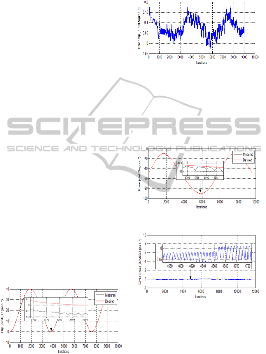
We present in figure (7) the behavior of the
controller and in figure (8) the evolution of the error
for the three joints (hip, knee and ankle). The
variation of the rehabilitation chair first joint (hip) in
its trajectory is shown in (Figure-7). Figure 8
illustrates the error between the desired and
measured value.
Figure 7: Varying the path of the first joint (hip joint).
Figure 8: The error in the desired trajectory of the first
joint (hip joint).
We generate desired positions joint in the
operating range of the hip joint of the rehabilitation
device, the signal varies between 0° and 40° and as a
starting point 0°. The output obtained (real position
joint) are identical with the signal desired, which
gave an error not exceeding 0.17°.
Figures (9, 10) represent respectively the
variation of the second joint (knee) and its error.
Figure 9: Varying the path of the second joint (Knee
joint).
Figure-10: The error in the desired trajectory of the second
joint (Knee joint).
For the knee joint, the signal is also sinusoidal
shape varying between -30° and -90°, as a starting
point -50°, this range was chosen based on the
operating range of rehabilitation device. The output
signal is obtained similar to the desired signal, the
highest value of the error obtained is 0.1°. The
NeuralNetworksControlerofaLowerLimbsRoboticRehabilitationChair
69
starting point we got an error of 10°, this is due to
the initial position of the joint.
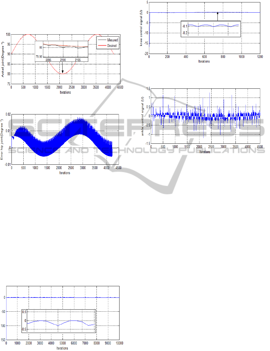
At the end, the variation of the ankle joint and
it’s error are illustrated in (Figures 11 and 12).
Figure 11: Varying the path of the third joint (Ankel joint).
Figure 12: The error in the desired trajectory of the third
joint (Ankel joint).
For the ankle joint, the signal that we generated
varies between 80° and 100°, with 90° initial value.
The output signal is virtually identical to the desired
signal; as a result we had a very weak error, less
than 0.02°.
The plots show that the obtained results are very
good, as the measured values are very close to the
desired ones. In fact, the error’s values does not
exceed (0.2°) most. Nevertheless, the error signals
present considerable oscillation cycle.
Corresponding control signal of the three joints
are shown in Figures (13, 14 and 15)
Figure 13: Control signal (U) of the first joint (hip joint).
Figure 14: Control signal (U) of the second joint (Knee
joint).
Figure 15: Control signal (U) of the third joint (Ankel
joint).
The variation of the amplitude of the control
signal of the three joints is not very intense, we
believe that it is optimal signals, which gave good
performance in the trajectory tracking with very low
error.
6 DISCUSSION AND
CONCLUSIONS
The objective of this work is to establish an
intelligent control law using neural networks for the
kinematic model of the robotic rehabilitation chair of
the lower limbs. This is latter consists of two
orthesis operating in three degrees of freedom. The
implementation of the control law is performed by
generating a similar signal (closer) to the
physiological joint trajectories. To obtain the
smallest possible error and try to get a signal error
with the least possible oscillations, we performed
several learning attempts, with a more or-less long
time. A high frequency of oscillation of the error
signal involves a large variation in the control signal,
which is harmful for the electronic components,
such as motors. However, once this step is done, the
controller performs very well. The implemented
control law gives very good performance. Indeed the
BIODEVICES2014-InternationalConferenceonBiomedicalElectronicsandDevices
70

error of each joint is very small; it does not exceed
(0.2 °). The results are satisfying. However, the error
form of each joint signal has thousands of
oscillations. These oscillations are due to variations
in the successive orders. By varying the desired
signal very quickly, the controller will not be able to
follow; it will give a very big order which leaves the
workspace of the chair. Perspectives, The patient's
weight which varies from one individual to another,
can be regarded as a parameter. Than considered as
an extrinsic disturbance. We propose to improve the
monitoring of the path by using a dynamic model of
the robot in order to take into account all the
parameters and to achieve high accuracy and
minimized oscillations on the output signal.
REFERENCES
Akdogan, E., Adli, M, A., 2011. The disgn and control of
a therapeutic exercise robot for lower limb
rehabilitation: physioterabot. In MECHATRONIC,
21: 509-522.
Anama, K., Al-Jumailyb, A, A., 2012. Active exoskeleton
control systems: State of the art. In Procedia
Engineering, 41: 988-994.
Bhangale, PP., Saha, SK., Agrawal, VP., 2004. A
Dynamic Model Based Robot Arm Selection
Criterion. In Multibody System Dynamics, 12: 95-115.
Corke, P., 2011. Robotics, Vision and Control
Fundamental Algorithms in MATLAB. In Springer.
ISBN: 978-3-642-20143-1.
Dombre, E., Khalil, W., 2007. Robot manipulators,
modeling performance and analysis and control. In
ISTE, ISBN 10: 1-905209-10-X.
Fu, K, S., 1987. Robotics: Control, Sensing, Vision, And
Intelligence. The book,McGraw-Hill Book Company.
1987. ISBN: 0-07-022625-3.
Jamwal, P, K., Xie, S., Aw, K, C., 2009.Kinematic design
optimization of a parallel ankele rehabilitation robot
using modified geneticalgorithm. In Robotics and
Autonomous Systems. 57: 1018–1027.
Jazar, R, N., 2010. Theory of Applied Robotics
Kinematics, Dynamics and Control. In Springer.
ISBN: 978-1-4419-1749-2.
Khalil, W., Dombre, E., 2004.Modeling, identification and
control of robots. In Kogan page science. ISBN: 1-
9039-9666-X.
Khalil, W., 2010. Dynamic modeling of robots using
recursive newton-euler techniques. In ICINCO2010,
Portugal,7: 19-31.
Lo, H, S., Xie, S, Q,. 2012. Exoskeleton robots for upper-
limb rehabilitation: State of the art and future
prospects. In Medical Engineering & Physics, 34:261-
268.
Marchal-Crespo, L., Reinkensmeyer1, D, J., 2009. Review
of control strategies for robotic movement training
after neurologic injury. In Journal of Neuro
Engineering and Rehabilitation, 6: 20,
http://www.mathworks.com/help/nnet/ref/trainlm.html.
Merrouche, l, M., 2011. Conception d’orthèses
fonctionnelles pour les paraplégiques. Mémoire,
USTHB, Alger mars 2011.
Moughamir, S., Deneve, A., Zaytoon, J., Afilal, L., 2005.
Hybrid force/impedance control for the robotized
rehabilitation of the upper limbs. In IFAC World
Congress, 16: 2169-2169.
Rahman, M. H., Kiguchi, K., Rahman, M, M., Sasaki, M.,
2006. Robotic exoskeleton for rehabilitation and
motion assist. In International conference on
industrial and information systems, 2: 241-6.
Reinkensmeyer, D. J., Emken, J. L., Cramer, SC., 2004.
Robotics, motor learning, and neurologic recovery. In
Annual Review of Biomedical Engineering, 6:497-525.
Riener, R., Nef, T., Colombo, G., 2005. Robot-aided
neurorehabilitation of the upper extremities. In Med
Biol Eng Comput, 43(1):2-10.
Saadia, N., Djezzar, K, B., Abdenbi, M., Ziri , N.,
Merrouche , L., Ababou , A., Ababou, N., 2009.
Dispositif Automatique de Rééducation Fonctionnelle
des membres inférieurs. In CGE, Alger,6.
Schmitt, C., Métrailler, P., Al-Khodairy, A., Brodard, R.,
Fournier, J., Bouri, M., Clavel, R., 2004. The motion
maker ™: a rehabilitation system combining an
orthosis with closed-loop electrical muscle
stimulation». In 8
th
Vienna International Workshop on
Functional Electrical Stimulation.
Seddiki, L., Guelton, K., Mansouri, B., Zaytoon, J., 2006.
H-infinity Takagi-Sugeno fuzzy control of a lower
limbs rehabilitation device. In International
Conference on Control Applications. 06: 927-932.
Spong, M, W., Hutchinson, S., 2005. Robot modeling and
control. In JOHN WILEY & SONS, ISBN-10:
0471649902.
Zeinali, M., Notash, L., 2010. Fuzzy logic based hybrid
impedance/force control for upper limbs robotized
rehabilitation. In Transactions of the Canadian Society
for Mechanical Engineering. 34: 137-150.
NeuralNetworksControlerofaLowerLimbsRoboticRehabilitationChair
71
