
Impact of Multi-Rate and Multi-Format Crosstalk Signals on the
Performance of 40 Gbit/s DQPSK Optical Receivers
João L. Rebola
1,2
, Luís G. C. Cancela
1,2
and João J. O. Pires
1,3
1
Instituto de Telecomunicações, Av. Rovisco Pais 1, 1049-001 Lisboa, Portugal
2
Department of Information Science and Technology, Instituto Universitário de Lisboa (ISCTE-IUL),
Av. das Forças Armadas, Edifício II, 1649-026 Lisboa, Portugal
3
Department of Electrical and Computer Engineering, Instituto Superior Técnico, Lisboa, Portugal
Keywords: Differential Quadrature Phase-Shift Keying, In-band Crosstalk, Monte Carlo Simulation, Optical Receivers.
Abstract: The coexistence of signals with different modulation formats and different bit rates in metropolitan optical
networks is, nowadays, a reality. In-band crosstalk can be very detrimental to the performance of those
networks. In this work, the impact of in-band crosstalk due to multi-format and multi-rate signals on the
performance of 40 Gbit/s DQPSK optical receivers is evaluated. It is shown that the worst interferer is the
10 Gbit/s OOK signal, which is the most common modulation format in today’s optical networks.
1 INTRODUCTION
Optical transport networks are, currently,
characterized by their ability to transport signals
with multiple modulation formats and a multitude of
bit rates and the actual trend is to further increase the
number of different formats and bit rates that coexist
in the network (Nag, 2010). The main reason for this
increase is the widespread use of coherent
technology and the flexibilisation of the 50 GHz
optical grid – the so called flexgrid (Sambo, 2012).
Nevertheless, this technology, that allows the use of
advanced modulation formats with greater spectral
efficiency and increased signal bit rate, is mostly
used in long-haul networks (Winzer, 2012). On the
other hand, optical metropolitan area networks
(MANs) are still based in intensity modulation direct
detection systems, because of their simplicity and
low power consumption characteristics. The typical
signals coexisting in these metro networks are the
10 Gbit/s OOK (On-Off Keying) and DPSK
(Differential Phase-Shift Keying) signals, and the
40 Gbit/s DPSK and DQPSK (Differential
Quadrature Phase-Shift Keying) signals.
The physical constraints of optical MANs are an
important issue in network planning and
performance evaluation. In particular, in-band
crosstalk is considered an important physical
limitation (Monroy, 2002). The impact of this
phenomenon has been intensively studied in direct
detection systems. In the majority of these studies, it
is assumed that the crosstalk signals have the same
bit rate and modulation format than the selected
signal. Examples of these studies for OOK, DPSK
and DQPSK signals are, respectively, given in
(Attard, 2005), (Pires, 2010) and (Cancela, 2012).
There are also a few studies which consider that the
selected signal has a different bit rate and
modulation format than the crosstalk signals
(Cancela, 2013), (Filer, 2010). In (Cancela, 2013),
an analytical formalism is used to evaluate the
impact of a single OOK interferer in a DPSK
system, and in (Filer, 2010) the impact of a single
OOK/DPSK/DQPSK interferer in a DPSK system is
evaluated in an experimental and simulation setup.
In this work, we extend these studies and
evaluate the impact of in-band crosstalk due to
10/40 Gbit/s OOK/DPSK/DQPSK multiple
interferers on the performance of 40 Gbit/s DQPSK
optical receivers. The crosstalk impact is evaluated
by Monte Carlo (MC) simulation, and an analytical
formalism based on the moment generating function
(Cancela, 2012) is used to validate the MC
simulation for the single interferer scenario. The
impact of the extinction ratio of OOK signals and
the impact of the crosstalk signal duty cycle on the
receiver performance are also assessed.
This paper is structured as follows. Section 2
describes the simulation model to assess the impact
of multi-format interferers in a DQPSK receiver.
56
L. Rebola J., G. C. Cancela L. and J. O. Pires J..
Impact of Multi-Rate and Multi-Format Crosstalk Signals on the Performance of 40 Gbit/s DQPSK Optical Receivers.
DOI: 10.5220/0004700900560062
In Proceedings of 2nd International Conference on Photonics, Optics and Laser Technology (PHOTOPTICS-2014), pages 56-62
ISBN: 978-989-758-008-6
Copyright
c
2014 SCITEPRESS (Science and Technology Publications, Lda.)

)(tE
)(tE
()
Et
()
s
Et
,
1
()
M
ci
i
Et
()
ASE
Et
Figure 1: Block diagram of the DQPSK optical receiver.
Numerical results are discussed in Section 3 and
conclusions are presented in Section 4.
2 SYSTEM DESCRIPTION
In this section, the model used to characterise the
DQPSK optical receiver is described. The
implementation of the MC simulator used to assess
the performance of the optical receiver when
impaired by in-band crosstalk is also presented.
2.1 Optical DQPSK Receiver
The structure of a typical differential direct detection
DQPSK receiver is depicted in Figure 1 (Ho, 2005).
It consists of an optical pre-amplifier with a constant
power gain
G
over the amplifier bandwidth; an
optical filter with –3 dB bandwidth
;
o
B and a 3 dB
coupler to split the signal between the two branches
of the optical receiver. Each branch of the optical
receiver consists of a delay line interferometer with a
differential delay equal to the symbol period T
s
; a
balanced photodetector; and a post-detection
electrical filter with –3 dB bandwidth
.
e
B
In the
lower branch (Q), the arms of the interferometer have
a phase difference of
/4, while in the upper branch
(I), the interferometers arms phase difference is
/4
(Ho, 2005). Throughout this work, the possible
imperfections of the optical DQPSK receiver are
neglected.
The electrical field at the optical filter output,
(),Et
can be expressed as (Cancela, 2012)
,
1
() () () ()
M
sciASEo
i
E
tGEtGEtEtht
(1)
where
stands for convolution and
()
o
ht
is the
impulse response of the optical filter. The first term
of Eq. (1),
(),
s
Et
corresponds to the electrical field of
the incoming DQPSK signal, named selected signal
and is described as
() exp () ,
s
sss
Et P j t e
where P
s
is the average signal power at the optical
pre-amplifier input;
()
s
t
is the signal phase that
carries the DQPSK symbol information, with
possible values
4,43,43,4
; and
s
e
is
the signal polarization unit vector.
The second term of Eq. (1),
,
1
(),
M
ci
i
Et
corresponds to the electrical field of the in-band
crosstalk, with M possible interferers. The complex
envelope of the i-th crosstalk signal field can be
represented as
,,,,
,,,
()
exp ( )
ci ci ci ci
ci ci ci c
Et PAt
j
te
(2)
where P
c,i
is the crosstalk power. The crosstalk level
of the i-th interferer is defined as the ratio between
the crosstalk power, P
c,i
, and the signal power, P
s
.
The total crosstalk level is the sum of the crosstalk
levels of the M interferers. In Eq.
,,,,
,,,
()
exp ( )
ci ci ci ci
ci ci ci c
Et PAt
j
te
(2)
,
,ci
is a random time shift within one symbol
period, which is modelled considering a uniform
distribution over that period (Winzer, 2005);
,ci
is
a random phase difference with respect to the
selected signal, which is modelled considering a
ImpactofMulti-RateandMulti-FormatCrosstalkSignalsonthePerformanceof40Gbit/sDQPSKOpticalReceivers
57

uniform distribution over the interval [0, 2[
(Winzer, 2005);
c
e
is the crosstalk signal polarisation
unit vector, which as a worst-case assumption is
assumed co-polarised with the selected signal,
s
c
ee
;
,
()
ci
A
t
and
,
()
ci
t
are, respectively, the envelope
and the phase of the crosstalk signal, which define
the modulation format of the i-th interferer. The
modulation formats and bit rates of the crosstalk
signal considered in this work are 10 Gbit/s OOK, 10
Gbit/s DPSK, 40 Gbit/s OOK, 40 Gbit/s DPSK and
40 Gbit/s DQPSK. The extinction ratio of the OOK
crosstalk signals is defined as
10
rPP
, with
1
P
defining the average power of the bits ’1’ and
0
P
the
average power of the bits ‘0’. The duty-cycle of RZ
(Return-to-Zero) pulses, D, is defined as the fraction
of time that a rectangular pulse lasts within a symbol
period, before it returns to zero.
The third term of Eq. (1),
(),
ASE
Et
corresponds to
the complex envelope of the electrical field of the
amplified spontaneous emission (ASE) noise
originated at the optical pre-amplifier. The ASE
noise is assumed as a zero mean white stationary
Gaussian noise with single-sided power spectral
density in each polarisation described by
/2,
os
NhvGF
where
s
hv
is the photon energy at
the signal wavelength, and
F
is the pre-amplifier
noise figure.
The 3 dB couplers and delay interferometers are
modelled as in (Seimetz, 2009). For the I branch, the
electrical fields
()Et
and
()Et
are described by
() ( ) exp 4
()
1
() ( ) exp 4
()
22
s
s
jE t jE t T j
Et
Et Et T j
Et
(3)
Using the same model described in (Seimetz, 2009),
the electrical fields after the delay line interferometer
of the Q-branch of the optical receiver can be readily
calculated. The photodetectors are modelled as ideal
square-law detectors.
2.2 Monte Carlo Simulation
In the MC simulation, a sequence of bits of length
N
b
corresponding to the information carried by the
DQPSK selected signal is generated using deBruijn
sequences (Jeruchim, 2000). The differential
encoding and conversion to quaternary symbols with
Gray coding follows (Ho, 2005) and (Costa, 2010).
Then, the sequence of symbols is discretized in N
a
samples per symbol, which allows considering the
signal waveform within a symbol period [for
example, non-RZ (NRZ) or RZ pulses]. Hence, the
effect of intersymbol interference on the
performance of the DQPSK optical receiver can be
rigorously evaluated on the MC simulation.
In the simulator, the ASE noise is generated
using a random number generator, which follows a
Gaussian distribution with zero mean and variance
of N
o
B
sim
, where B
sim
is the bandwidth used in the
MC simulation. In each iteration of the simulation, a
sample function of the ASE noise is generated
(Jeruchim, 2000).
At that same iteration, a sample function of the
crosstalk signal is also constructed. Each i-th
crosstalk signal is generated considering a random
sequence of bits, which are, then modulated. The
same modulation format is considered for all i-th
crosstalk signals.
After the generation of selected signal, crosstalk
signal and ASE noise sample functions, the
electrical field given in Eq. (1) is obtained and is
propagated through the DQPSK optical receiver
depicted in Figure 1. The current at the output of the
I branch and Q branch is, then, determined and
sampled at the time instants corresponding to the
maximum eye-opening obtained without noise and
crosstalk. After sampling, each received bit in its
respective branch, which is corrupted by noise and
crosstalk, is compared to the corresponding
transmitted bit to find out if an error has occurred.
The bit error probability (BEP) is, then, calculated
from (Costa, 2010)
2
I
Q
BEP BEP
BEP
(4)
where
I
BEP
and
Q
BEP
are the bit error
probabilities, respectively, of the I and Q branches,
which are estimated through direct error counting
using
,
2
EI
I
it b
N
BEP
NN
(5)
,
2
EQ
Q
it b
N
BEP
NN
(6)
where N
it
is the number of iterations of the MC
simulation, which is equivalent to the number of
simulated sample functions and N
E,I
and N
E,Q
are the
number of counted errors, respectively, in the I and Q
branches of the receiver. A specific number of
counted errors is set as a stopping criterion of the MC
simulation.
PHOTOPTICS2014-InternationalConferenceonPhotonics,OpticsandLaserTechnology
58

3 NUMERICAL RESULTS
In this section, the impact of multi-format and multi-
rate crosstalk signals on the performance of 40 Gbit/s
DQPSK pre-amplified optical receivers is evaluated
using MC simulation. The duty-cycle variation of the
crosstalk signals, the extinction ratio variation of
OOK crosstalk signals and single and multiple
interference are considered in these studies.
Throughout this section, the amplifier noise
figure, F, is 5 dB, the pre-amplifier gain, G, is 30 dB,
and both ASE noise polarisations are considered. The
optical filter is a Gaussian filter with normalized
3 dB bandwidth given by
5
os
BT
. The electrical
filter is a Gaussian filter with normalized 3 dB
bandwidth given by
0.7
es
BT
. The optical signal-
to-noise ratio (OSNR) is measured in the reference
bandwidth of 0.1 nm at
s
=
1550 nm. The total
crosstalk level considered for the interferers is
13 dB, for all data rates and modulation formats.
This means that the power corresponding to the sum
of powers of each individual interferer is 13 dB
below the original DQPSK signal power. We also
assume that the power is equally distributed by the
interferers. The modulation formats of the crosstalk
signal considered are 10 Gbit/s OOK, 10 Gbit/s
DPSK, 40 Gbit/s OOK, 40 Gbit/s DPSK and
40 Gbit/s DQPSK. The bit rate of the selected
DQPSK signal is 40 Gbit/s. The number of simulated
bits is N
b
=
2
7
, N
a
=
128 samples per symbol and
B
sim
=
5.1 THz are used. The BEP is estimated using
MC simulation considering at least N
E,I
= 1000 or
N
E,Q
= 1000 counted errors.
3.1 Single and Multiple Interference in
Multi-rate and Multi-format
Scenarios
In this subsection, the impact of multi-rate and multi-
format crosstalk signals on the selected DQPSK
signal is evaluated. The pulse shape of all modulation
formats is NRZ and the extinction ratio of the OOK
interferers is ideal,
r
. The influence of the
random time shift
,ci
is neglected, since it has been
verified that its influence on the receiver performance
is minor, when considering NRZ pulse shapes.
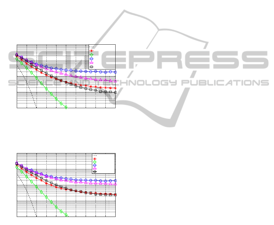
Figure 2 shows the BEP as a function of the
OSNR, for a single interferer, M = 1, with different
modulation formats and bit rates on the crosstalk
signal. The BEP obtained without crosstalk is also
depicted in Figure 2 for comparison purposes. To
check the MC simulation results, the BEP is also
computed using the analytical formalism (A)
proposed in (Cancela, 2012), considering the absence
of crosstalk and a 40 Gbit/s DQPSK crosstalk signal.
This analytical formalism uses an eigenfunction
expansion technique to decompose signal, crosstalk,
and ASE noise, at the optical filter input, in a series
of orthogonal functions and relies on the moment
generating function to describe the decision variable
statistics. From Figure 2, a good agreement between
simulation and analytical results is observed.
Figure 2 shows that the 10 Gbit/s OOK crosstalk
signal leads to the most severe interference on the
40 Gbit/s DQPSK optical receiver. For very high
OSNR, the BEP is reaching a floor. The 40 Gbit/s
OOK interferer leads to the second worst BEP
degradation, especially for OSNRs above 17 dB,
where the signal-crosstalk beating power is becoming
significant. The 40 Gbit/s DQPSK and 10 Gbit/s
DPSK crosstalk signals provide similar
performances, while the less harmful interferer is the
40 Gbit/s DPSK. As a main conclusion, the
interference of amplitude modulated signals leads to
higher BEP degradation than phase-modulated
signals interference. This conclusion is in agreement
with the results presented in (Filer, 2010) for a single
interferer and considering a 40 Gbit/s DPSK signal as
the selected signal. This conclusion is similar to the
one found in the presence of cross-phase modulation
(XPM) (Sambo, 2012). Amplitude modulated signals
at 10 Gbit/s induce a higher XPM on coexisting
phase modulated signals at higher bit rates, and as a
result, lead to higher performance degradation.
Figure 2: BEP as a function of the OSNR for a single
interferer, M = 1 and different modulation formats and bit
rates on the crosstalk signal.
It is still an open issue if this scenario is kept for
M > 1. Figures 3 and 4 depict the BEP as a function
of the OSNR for, respectively, M = 4 and M = 8
interferers, considering different modulation formats
and bit rates on the crosstalk signals. It should be
pointed out that, we have considered that, all M
12 14 16 18 20 22 24 26 28 30 32
10
−4
10
−3
10
−2
10
−1
OSNR [dB]
Bit error probability
Without crosstalk
40 Gbit/s OOK
40 Gbit/s DPSK
10 Gbit/s OOK
10 Gbit/s DPSK
40 Gbit/s DQPSK
Without crosstalk (A)
40 Gbit/s DQPSK (A)
ImpactofMulti-RateandMulti-FormatCrosstalkSignalsonthePerformanceof40Gbit/sDQPSKOpticalReceivers
59
interferers have the same modulation format and bit
rate.
Figure 3 shows that, for M = 4, the BEP reaches
a floor for high OSNRs for all crosstalk signals,
except for the 40 Gbit/s DPSK interferer case. For
such high OSNRs, the beating between signal and
crosstalk is dominating the optical receiver
performance, and the power increase of the selected
signal gives no longer any performance
improvement. The higher BEP degradation occurs
also for the 10 Gbit/s interferer. However, in
comparison with M = 1, the 10 Gbit/s DPSK
interferer leads to a higher BEP degradation than
40 Gbit/s OOK and DQPSK signals, which exhibit a
similar performance.
Figure 3: BEP as a function of the OSNR for M = 4
interferers and different modulation formats and bit
rates on the crosstalk signal.
Figure 4: BEP as a function of the OSNR for M = 8
interferers and different modulation formats and bit
rates on the crosstalk signal.
Figure 4 shows the enhancement of the
behaviours observed in Figure 3, with the increase of
the interferers number. The 40 Gbit/s OOK and
40 Gbit/s DQPSK crosstalk signals lead practically
to the same receiver performance. The BEP with the
10 Gbit/s DPSK crosstalk signal is becoming similar
with the 10 Gbit/s OOK crosstalk signal. Notice that
between Figures 3 and 4, the increase on the number
of interferers had no particular influence on the BEP,
when considering the 10 Gbit/s OOK signal. This
means that the superposition of the symbol patterns
of the interferers is not contributing for further
degradations of the receiver performance. For the
40 Gbit/s DPSK crosstalk signal, the increase of the
number of interferers practically does not influence
the BEP.
As a main conclusion, we have seen that with the
increase on the number of interferers, the slower bit
rate signals, 10 Gbit/s, are the ones that lead to a
higher BEP degradation. As the bit rate is smaller,
when there is a combination of symbols on the
crosstalk signals that impairs significantly the
receiver performance, it affects at least four times
the same number of symbols on the selected
40 Gbit/s DQPSK signal.
3.2 Duty-cycle and Extinction Ratio
Variation
In this subsection, the influence of the duty-cycle of
the crosstalk signals on the receiver performance is
investigated. All results are obtained considering a
40 Gbit/s DQPSK NRZ signal and M = 4 interferers.
In these studies, the influence of a random time shift
,ci
inside the symbol period is taken into account
in the BEP estimation. Although the main qualitative
conclusions are not changed, the values of the BEP
may differ noticeably, when neglecting this random
time shift for interferers with RZ pulse shape.
Some final results discussing the influence of the
extinction ratio of OOK interferers on the receiver
performance are also presented.
Figures 5, 6 and 7 show the BEP as a function of
the OSNR for, respectively, 10 Gbit/s OOK,
10 Gbit/s DPSK and 40 Gbit/s DQPSK crosstalk
signals, for several duty-cycles. The extinction ratio
of the OOK interferers is assumed ideal,
r
.
Figures 5-7 show that the reduction of the duty-
cycle of the interferers reduces the crosstalk impact
on the receiver performance. For very low duty-
cycles (below 20%), the BEP estimated in the
presence of crosstalk becomes very close to the BEP
estimated in its absence. With the duty-cycle
reduction, the fraction of time of the pulse that is
interfering with one pulse of the selected signal is
becoming smaller, and the crosstalk impact on the
receiver performance is decreased, although the total
crosstalk power is the same.
Similar conclusions to those taken from Figures
5-7 have been drawn when considering 40 Gbit/s
12 14 16 18 20 22 24 26 28 30 32
10
−4
10
−3
10
−2
10
−1
OSNR [dB]
Bit error probability
Without crosstalk
40 Gbit/s OOK
40 Gbit/s DPSK
10 Gbit/s OOK
10 Gbit/s DPSK
40 Gbit/s DQPSK
12 14 16 18 20 22 24 26 28 30 32
10
−4
10
−3
10
−2
10
−1
OSNR [dB]
Bit error probability
Without crosstalk
40 Gbit/s OOK
40 Gbit/s DPSK
10 Gbit/s OOK
10 Gbit/s DPSK
40 Gbit/s DQPSK
PHOTOPTICS2014-InternationalConferenceonPhotonics,OpticsandLaserTechnology
60
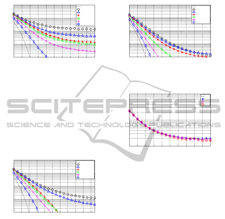
Figure 5: BEP as a function of the OSNR for
10 Gbit/s OOK crosstalk signal with M = 4 and
different duty-cycles.
OOK and 40 Gbit/s DPSK crosstalk signals.
Figure 8 depicts the BEP as a function of the
OSNR for 10 Gbit/s OOK NRZ crosstalk signals,
with the extinction ratio as a parameter. Figure
8
shows that the 40 Gbit/s DQPSK optical receiver
performance is practically independent of the
extinction ratio of the interferer. The same
conclusion has been drawn for the 40 Gbit/s OOK
interferer and is in agreement with the results
presented in (Cancela, 2013) for DPSK optical
receivers.
Figure 6: BEP as a function of the OSNR for
10 Gbit/s DPSK crosstalk signal with M = 4 and
different duty-cycles.
4 CONCLUSIONS
In this work, the impact of in-band crosstalk due to
multi-rate and multi-format interferers on the
performance of 40 Gbit/s DQPSK optical receivers
has been assessed using MC simulation.
It has been shown that the 10 Gbit/s OOK
interferer, which is the traditional modulation format
of optical communication systems, is the one that
leads to the highest performance degradation of
Figure 7: BEP as a function of the OSNR for
40 Gbit/s DQPSK crosstalk signal with M = 4 and
different duty-cycles.
Figure 8: BEP as a function of the OSNR for
10 Gbit/s OOK NRZ crosstalk signal with M = 4 and
different extinction ratios.
the 40 Gbit/s DQPSK receiver. For a high number of
interferers, slower bit rates, i. e., 10 Gbit/s, on the
crosstalk signals are the most detrimental to the
receiver performance. The crosstalk induced by
40 Gbit/s DPSK signals is the less harmful and is
practically independent of the number of interferers.
It has been shown that the reduction of the duty-
cycle of the interferers decreases the crosstalk
impact on the receiver performance and that the
influence of the OOK interferer extinction ratio on
the DQPSK receiver performance is practically
negligible.
ACKNOWLEDGEMENTS
This work was supported by Instituto de
Telecomunicações of Portugal within the project
IXOS3D – PEst-OE/EEI/LA0008/2011.
12 14 16 18 20 22 24 26 28 30 32
10
−4
10
−3
10
−2
10
−1
OSNR [dB]
Bit error probability
Without crosstalk
D = 80%
D = 67%
D = 50%
D = 33%
D = 20%
D = 10%
12 14 16 18 20 22 24 26 28 30 32
10
−4
10
−3
10
−2
10
−1
OSNR [dB]
Bit error probability
Without crosstalk
NRZ
D = 80%
D = 50%
D = 33%
D = 20%
D = 10%
12 14 16 18 20 22 24 26 28 30 32
10
−4
10
−3
10
−2
10
−1
OSNR [dB]
Bit error probability
Without crosstalk
NRZ
D = 67%
D = 50%
D = 33%
D = 20%
D = 10%
12 14 16 18 20 22 24 26 28 30 32
10
−3
10
−2
10
−1
OSNR [dB]
Bit error probability
r = ∞
r = 30
r = 20
r = 10
ImpactofMulti-RateandMulti-FormatCrosstalkSignalsonthePerformanceof40Gbit/sDQPSKOpticalReceivers
61

REFERENCES
Attard, J., Mitchell, J., Rasmussen, C., 2005,
“Performance analysis of interferometric noise due to
unequally powered interferers in optical networks”,
Journal of Lightwave Technology, vol. 23, no. 4, pp.
1692-1703, Apr.
Cancela, L., Rebola, J., Pires, J., 2012, In-Band Crosstalk
tolerance of direct detection DQPSK optical systems,
IEEE Photonics Conference IPC, Burlingame,
California, USA.
Cancela, L., Rebola, J., Pires, J., 2013, Analytical
Assessment of the Impact of OOK Crosstalk Signals
on a DPSK Direct Detection System, Conference on
Telecommunications Conftele, Castelo Branco,
Portugal.
Costa, N., Cartaxo, A., 2010, “Optical DQPSK modulation
performance evaluation”, Book chapter in Advances in
Lasers and Electro Optics, In-Tech, pp. 427-452, Apr.
Filer, M., Tibuleac, S., 2010, Impact of ROADM In-band
Crosstalk on 40G DPSK signals, Conference of
Optical Fiber Communication OFC, San Diego,
California, USA.
Ho, K., 2005, Phase-Modulated Optical Communication
Systems, Springer, New York, USA, 1
st
edition.
Jeruchim, M., Balaban, P., Shanmugan K., 2000,
Simulation of Communication Systems – Modeling,
Methodology and Techniques, Kluwer Academic /
Plenum Publishers, New York, USA, 2
nd
edition.
Monroy, I., Tangdiongga, E., 2002, Crosstalk in WDM
Communication Networks, Kluwer Academic
Publishers, 1
st
edition.
Nag, A., Tornatore, M., Mukherjee, B., 2010, “Optical
network design with mixed line rates and multiple
modulation formats”, Journal of Lightwave
Technology, vol. 28, no. 4, pp. 466-475, Feb. 15.
Pires, J., Cancela, L., 2010, “Estimating the performance
of direct-detection DPSK in optical networking
environments using eigenfunction expansion
techniques”, Journal of Lightwave Technology, vol.
28, no 13, pp. 1994-2003, Jul. 1.
Sambo, N., Castoldi, P., Cugini, F., Bottari, G., Iovanna,
P., 2012, “Toward high-rate and flexible optical
networks”, IEEE Communications Magazine, vol. 50,
no. 5, pp. 66-72, May.
Seimetz, M., 2009, High-Order Modulation for Optical
Fiber Transmission, Springer-Verlag, Berlin,
Germany, 1
st
edition.
Winzer, P., Pfennigbauer, M., Essiambre, R., 2005,
“Coherent crosstalk in ultradense WDM systems”,
Journal of Lightwave Technology, vol. 23, no. 4, pp.
1734-1744, Apr.
Winzer, P., 2012, “High-spectral-efficiency optical
modulation formats”, Journal of Lightwave
Technology, vol. 30, no. 24, pp. 3824–3835, Dec. 15.
PHOTOPTICS2014-InternationalConferenceonPhotonics,OpticsandLaserTechnology
62
