
Analysis and Validation of AUTOSAR Models
Julian Kienberger
1
, Pascal Minnerup
2
, Stefan Kuntz
3
and Bernhard Bauer
1
1
Department of Computer Science, University of Augsburg, Augsburg, Germany
2
fortiss GmbH, An-Institut Technische Universit
¨
at M
¨
unchen, Munich, Germany
3
Division Powertrain, Continental Automotive GmbH, Regensburg, Germany
Keywords:
Data Dependency Analysis, AUTOSAR, Model-Driven Development, Multi-core, Parallelization.
Abstract:
As the rise of single-core processing power is exhausted due to technical limitations, the automotive branch is
forced to migrate its control unit software to architectures that feature multiple Independent Execution Units
(IEUs). This policy shift brings along new problems resulting from the tremendously increased complexity
of such systems. Facing these challenges, software engineers have to cope with possible data inconsistencies
caused by, e.g., race conditions or cycles. Being an important and standardized software architecture for elec-
tronic control units, the Automotive Open System Architecture (AUTOSAR) provides the basis for tools that
support the complexity handling when migrating to architectures with multiple IEUs. Our concept is realized
by a tool that executes data dependency analyses directly on AUTOSAR models, determines critical depen-
dencies, automatically solves trivial problems and provides semi-automatic resolution of advanced conflicts.
To support the actual parallelization of the system, the tool additionally determines groups of executable units
that are suitable to run on a common IEU. This appreciably facilitates the validation of AUTOSAR models
and the search for a good mapping of the processing tasks to IEUs.
1 INTRODUCTION
In recent years, it has become apparent that the per-
formance of single core processors is almost com-
pletely exhausted, because they are approaching their
limits concerning clock speed and memory speed
(Gleim and Sch
¨
ule, 2012). By all indications, the fur-
ther rising of the clock speed is unreasonable from
an economical and technical point of view, because
it inevitably leads to a disproportionate growth of
the CPU’s power consumption and an enormous rise
of the corresponding heat dissipation efforts (Sutter,
2005).
Nevertheless, car manufacturers and the asso-
ciated supplying industry are aiming at adding
further functionality to Electronic Control Units
(ECUs) which increases complexity as well as re-
quired processing performance (Deubzer et al., 2010;
Sch
¨
auffele and Zurawka, 2010). Moreover, they in-
tend to decrease the number of ECUs in order to save
space and reduce weight. These intentions strengthen
the endeavor to find a possibility for ramping up the
available computing power.
The development of embedded architectures that
feature multiple IEUs is a promising approach to meet
these recent challenges and is hence becoming in-
creasingly important (Wirbel, 2011). Therefore, the
companies of the automotive branch are migrating to
such architectures, which are often simply referred to
as “multi-core” architectures, although this is just one
specific solution that is frequently used to vicariously
represent the whole idea of parallel computing (Bohn
et al., 2011).
The distribution of the functional blocks, i.e.
atomic computational tasks, to several IEUs solves
the aforementioned problems with power consump-
tion, heat dissipation and processing performance.
However, it is eminently augmenting the complex-
ity of software due to dependencies between sep-
arately processed but still interdependent data ele-
ments including problems like race conditions, dead
locks, non-determinism and insufficient load balanc-
ing (Padberg and Denninger, 2013; Patterson, 2010).
Therefore new methods and tools are needed that as-
sist software engineers in designing and implement-
ing such systems (Multicore, 2011; Shih et al., 2009;
Eißenl
¨
offel, 2012).
One approach is AUTOSAR, which is a stan-
dardized platform developed by several leading man-
ufacturers and suppliers of the automotive sector.
274
Kienberger J., Minnerup P., Kuntz S. and Bauer B..
Analysis and Validation of AUTOSAR Models.
DOI: 10.5220/0004701002740281
In Proceedings of the 2nd International Conference on Model-Driven Engineering and Software Development (MODELSWARD-2014), pages 274-281
ISBN: 978-989-758-007-9
Copyright
c
2014 SCITEPRESS (Science and Technology Publications, Lda.)
AUTOSAR specifies a uniform software architecture
and defines interfaces for communication as well as
configuration formats which facilitate the exchange of
ECU software, assure its possible reuse and make it
scalable (AUTOSAR, 2013).
Hence, there is a strong demand for tools that
both harness the advantages of AUTOSAR and sup-
port the complexity handling when migrating to archi-
tectures featuring multiple IEUs (Sodan et al., 2010;
Gehrke et al., 2006). The latter is mainly about con-
flicts within specific execution sequences that can be
avoided by imposing constraints on the involved func-
tional blocks. Conflicts can be, e.g., data not being
available in time or data being read inconsistently.
Facing these problems, our research endeavors led
to the following concept:
• determination of the atomic execution units’ data
dependencies and their types by means of a static
data dependency analysis performed directly on
AUTOSAR models (Section 3)
• automatic imposition of mandatory constraints
and deduction of existing conflicts (Subsection
3.2)
• conflict detection and validation through provi-
sion of semi-automatic resolution actions (Sub-
section 3.3)
• determination and storage of virtually isolated
functional block regions to effectively support the
subsequent search for a proper “task to IEU” map-
ping when trying to parallelize a system (Section
4).
These aspects are framed by a description of the pre-
conditions and challenges (Section 2) and a case study
that illustrates the utilization of the tool (Section 5).
2 PRECONDITIONS AND
CHALLENGES
In order to properly understand the context of a data
dependency analysis involving execution orders, it is
crucial to be aware of the initial situation. Generally
speaking, there are two basic starting points:
• having a data dependency graph (without tim-
ing constraints imposed) and trying to specify a
proper execution order
• having already given an execution order and ana-
lyzing the “cycle problems” of the corresponding
data dependency graph
The former description corresponds to our use case.
The foundation of the analysis is a structural model
that does not contain any constraints. It merely con-
sists of AUTOSAR’s Software Components (SW-Cs)
together with their Internal Behavior including one or
more Runnable Entities (REs), which are the smallest
(and therefore the atomic) executable entities in the
scope of AUTOSAR. A sketch of such a model is
presented in Figure 1.
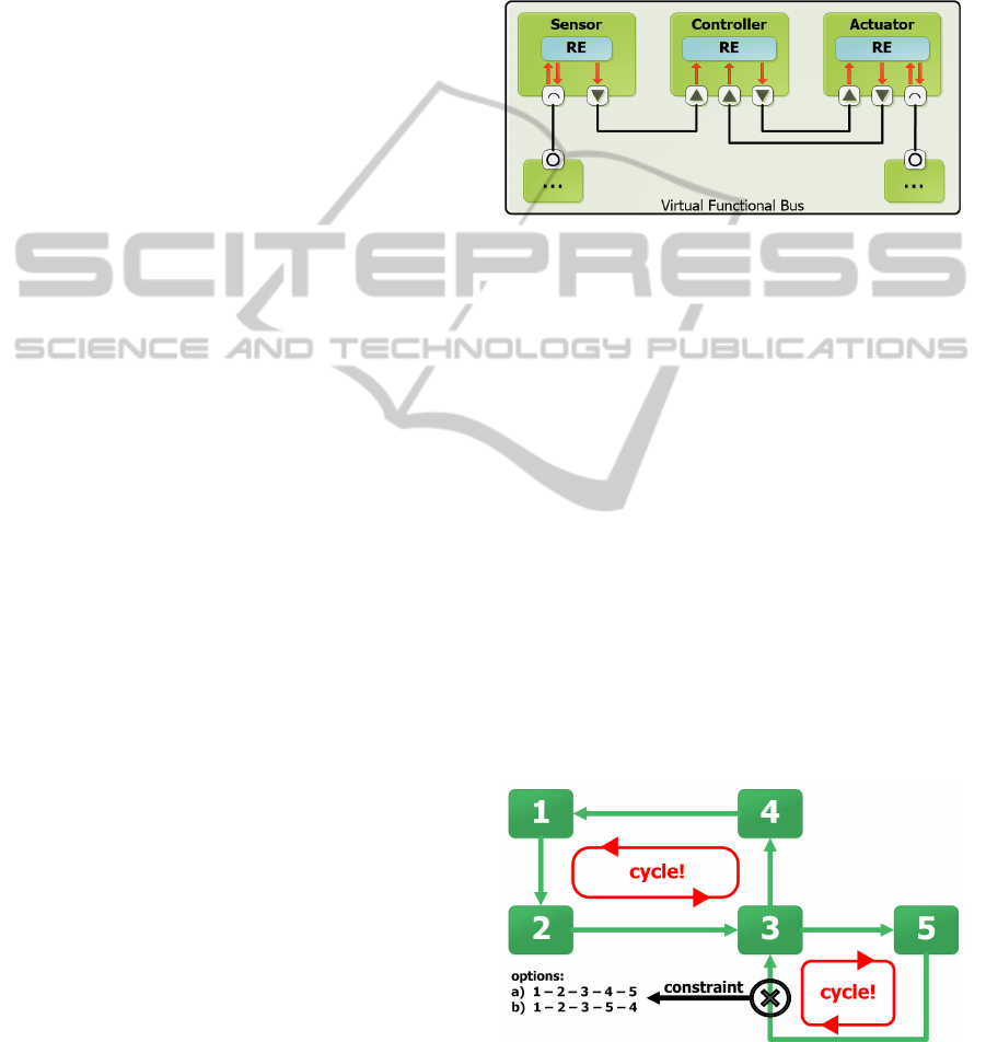
Figure 1: This simplified version of a typical sensor-actor
system is an example of a structural AUTOSAR model
without timing constraints. The arrows and the small black-
and-white boxes indicate the communication direction be-
tween the REs.
The Internal Behavior comprises the communica-
tion taking place within an SW-C (between several of
its REs) and between different SW-Cs. Since there
can be multiple instances of one single RE, it is im-
portant to mention that each instance is actually inde-
pendent and has its own data dependencies.
Such a dependency arises from the interaction be-
tween at least two Runnable Entity instances (REIs).
As each REI can read and write variables, a data
dependency between two REIs exists if, e.g., one
of them reads a variable that has been written by
the other one. Exceeding this trivial case, multiple
read/write actions can form a direct circular depen-
dency between two REIs or a transitive dependency
between multiple ones (a cycle). Figure 2 shows an
example conflict and its possible solution.
Figure 2: This figure shows a conflict example where the
calculated output from “REI 3” is a necessary input for the
calculation of “REI 5” and vice versa. This cycle has to be
broken up via a constraint that allows the transfered data to
be as old as one computing cycle or that imposes an execu-
tion order on the involved REIs (see Section 3.2).
AnalysisandValidationofAUTOSARModels
275

Cycles are particularly important as automotive
control software mainly runs periodic tasks, and it im-
mediately suggests itself to look upon the included
REIs from a temporal perspective. In this context, the
commonly used unit is “computing cycle”, which we
define as the time elapsed between two events that in-
volve periodically activated tasks being guided by the
slowest (least triggered) task occurring.
In a single-core system, the execution order of
the REIs has been carefully designed and tested ac-
cording to the knowledge about triggering frequen-
cies and computing cycles. Changing the execution
order can lead to an REI reading invalid data because
every data element has to be produced before it can
be consumed. However, such a rigid execution or-
der cannot be maintained when migrating to, e.g., a
multi-core system, because there is a need for more
freedom concerning the execution order of the REIs
that may run on different IEUs. Sticking to the heav-
ily constrained order of a single-core system would
result in using only one IEU. For a software engineer,
it is a tightrope walk to preserve as much freedom as
possible and simultaneously prevent the system from
entering problematic states that cause, e.g., race con-
ditions, data inconsistencies or dead locks. More-
over, too many constraints might impede achieving
a proper load balancing (equal IEU workloads) and
therefore the speedup, which is usually a major goal
of migration, can be appreciably restrained.
Facing the significant rise of the systems’ com-
plexity, it becomes clear that discovering possible
conflicts by use of data dependency analyses is vital
when several IEUs shall be used.
3 MODEL ANALYSIS AND
VALIDATION
Our concept is based on a static data dependency anal-
yses performed on AUTOSAR models. Its goals are
to discover design weaknesses, to automatically solve
trivial pitfalls, to support the elimination of the re-
maining conflicts (mainly cycles) and to write back
the modifications to the model. In detail, the con-
cept is to analyze the connections (data dependencies)
between the Executable Entities (i.e. the REIs) con-
tained in the SW-Cs and possible execution sequences
of them. By classifying the detected data dependen-
cies, it is feasible to restrict all possible execution se-
quences to a set that provides every REI with its re-
quired input data in time, which ensures that consis-
tency constraints are met.
3.1 Development and Scope
The implementation uses the Model Analysis Frame-
work (MAF), which is based on the Eclipse Modeling
Framework and provides “a core framework [...] al-
lowing the implementation of dynamic model anal-
ysis” (Saad, 2009; Eclipse Foundation, 2009). Its
main application (and our use case) is the execution
of data-flow analyses as described in (Saad and Bauer,
2013). Figure 3 shows MAF together with parts of the
Eclipse tool stack.
Figure 3: This figure illustrates the collaboration of MAF
with established frameworks and platforms for Eclipse as
well as with UML’s Object Constraint Language (OCL).
The implementation is realized as a plug-in for
the AUTOSAR Tool Platform (Artop), which serves
as Eclipse infrastructure for the construction of
AUTOSAR tools (Artop Group, 2012). It virtually
acts as “persistence layer” enabling common base
functionality like easy access on AUTOSAR mod-
els that adhere to specific AUTOSAR meta-model
versions. Its major components include features
like meta model implementations, model comparison,
model validation, explorers, editors and a code gener-
ation infrastructure.
For the processing, it is necessary to analyze the
specified Internal Behavior of the REIs. As SW-Cs
exchange data via so-called Assembly Connectors,
their connection points to a software component are
referred to as Ports. Port interfaces specify, e.g., vari-
ables, operations, triggers and mode switches of a port
when using the connectors. Regarding communica-
tion within SW-Cs, the data sent from an REI and re-
ceived by another one is represented as VariableAc-
cess (VA) connected to them. In general, variables
(as part of a port or local variables of a component)
play a significant role for the later analysis. There are
several kinds of VAs:
MODELSWARD2014-InternationalConferenceonModel-DrivenEngineeringandSoftwareDevelopment
276

• outgoing VAs:
- dataSendPoint
- dataWriteAccess
- writtenLocalVariable
• incoming VAs:
- dataReceivePointByValue
- dataReceivePointByArgument
- dataReadAccess
- readLocalVariable
The analysis concept covers all listed elements and
also includes data dependencies that arise from inter-
runnable communications of REIs in one (atomic)
SW-C.
3.2 Analysis Steps
The aforementioned MAF is used in the first phase of
the analysis. Here, the intermediate goal is to prop-
erly “prepare” the succeeding search of the model for
potentially problematic data dependencies. This is
done by annotating the AUTOSAR model and stor-
ing useful information in specific hash maps that sup-
port the efficient execution of the subsequent analysis.
To be exact, the model is traversed and relationships
like predecessors/successors are stored in “quick ac-
cess maps” (storage maps within MAF’s global object
container) in order to reduce the effort that is required
to navigate highly complex AUTOSAR models dur-
ing the analysis. In other words, the data flow analy-
sis is released from carrying out the same “expensive”
traversal steps and calculations several times by com-
puting required links once before the actual analysis
happens. This approach does tremendously speed up
the following search for dependencies. The created
quick access maps also enforce that only one data-
flow analysis result occurs for each object although
one single RE may be referenced several times in dif-
ferent contexts (RE instances).
Based on the data collected in this “pre-analysis”,
it is now possible to utilize the precomputed access
maps for quickly iterating over all instances of the
Runnable Entity that is currently being processed.
An instance can be referred to using the correspond-
ing RE in the AUTOSAR model together with the
path of the specific instantiation. In AUTOSAR, this
path is stored as a list of SwComponentPrototypes in
the ComponentInCompositionInstanceRef. Using this
path, the analysis can cope with the multiple instanti-
ations.
For finding the partner of data exchanges, two dif-
ferent cases have to be considered: the writing REI
can either access a variable within the SW-C (local
variables and inter-runnable variables) or outside the
SW-C via a port. If it accesses a local variable, the
consuming REI is the entity reading from the same lo-
cal variable. The only thing to note is that the reading
entity and the writing entity have to share the same in-
stantiation path as described above. This makes sure
that the REIs of the specific SwComponentPrototypes
are connected. If the writing REI accesses a port, the
connections of it have to be considered. It can be
connected to another port of a different component
using an AssemblySwConnector. The port receiving
the data can be accessed by an RE. The correct in-
stance of this RE is the consumer of the data depen-
dency. Alternatively the data can be delegated to a
port of an inner component using a DelegationCon-
nectorPrototype. In addition to these data dependen-
cies, AUTOSAR of course enables the modeling of
function calls that bring along data- and control-flow
dependencies.
Having found all data dependencies of the occur-
ring REIs, the next step is to set the execution of them
into an temporal perspective by determining whether
the dependencies act as Forward Dependency (FD) or
Backward Dependency (BD) with regards to their ex-
ecution order. FDs and BDs can be characterized as
follows:
• Forward Dependencies are marked by the fact
that in one computing cycle, the variables are first
written and afterwards read. In detail an “initial
REI” writes to a variable that is thereafter read
by a “target REI” which is a successor according
to the quick access maps created within the pre-
analysis.
• Backward Dependencies are all dependencies
remaining if FDs are not taken into consideration.
This means that a variable is first read and after-
wards written in the scope of one computing cy-
cle. Considering different computing cycles, the
very last access to a variable (before the comput-
ing cycle ends) is a write access. Accordingly,
the very first access to the variable is a read ac-
cess (before the variable is written respectively
updated in the same computing cycle). Here, the
“target REI” is not in the precomputed set of suc-
cessors.
In other words, no problems occur as long as the
producer of data is executed before any consumer.
A conflicting scenario would be, e.g., the following:
The data produced by “REI-1” is consumed by “REI-
2”, which uses it to produce new data. This data is
consumed by “REI-3” which is executed earlier than
“REI-1”. This results in a conflict due to inconsis-
tency, because “REI-3” uses “old” data for its pro-
cessing. Therefore the backward dependencies and
the cycles formed by them are the core problem.
AnalysisandValidationofAUTOSARModels
277

AUTOSAR provides several timing constraints
that solve such problems. We are using two of
them: ExecutionOrderConstraints (EOCs) and Age-
Constraints (ACs). The former “[...] is used to spec-
ify the order of execution of ExecutableEntities” and
the latter “[...] to specify a minimum and maximum
age that is tolerated when a variable data prototype is
received” (AUTOSAR, 2011).
Referring to the FDs, BDs and AUTOSAR’s con-
straints, our tool starts analyzing and categorizing the
identified dependencies. As stated before, it can au-
tomatically impose appropriate execution orders for
some “straight forward” data dependencies. This is
possible if there is a simple constellation like, e.g.,
two REIs that do not have further dependencies within
the system, so that there is no reason to execute the
consuming REI first. Hence, a newly created EOC
enforces the producing REI to be executed first.
In order to also detect non-trivial conflicts, the
analysis continues with subdividing the BDs into “in-
tentional” and “unintentional” ones. The former are
characterized by the existence of appropriate ACs ex-
plicitly allowing the transfered data to be as old as one
computing cycle. If no matching AC can be found,
the BD is probably unintentional. The set of remain-
ing BDs represent critical paths of the system’s de-
sign that need to be cared for manually by the engi-
neer. Basically, we suggest to explicitly state whether
a backward execution order for a data dependency is
allowed or not. Permissions for backward execution
are represented by ACs whereas EOCs are used for
their prevention. By imposing constraints on each po-
tential backward dependency, it is possible to ensure
the system’s validity with regard to data age consis-
tency.
As a final remark, it is important to mention that
cycles can only be formed by data dependencies that
actually depend on each other. This means that com-
munication contents (data units) sent to an REI have
to be indispensable for the REI’s upcoming calcula-
tion. This is being considered in our analysis.
3.3 Plugin and Editing
The analysis described above is carried out by our
tool that visualizes the results and provides semi-
automatic problem resolution for the detected con-
flicting data dependencies.
As stated, EOCs for obvious dependency cases
are automatically created. These EOCs are annotated
with the text string “computed EOC” in their corre-
sponding AUTOSAR category field. EOCs that are
marked like this should not be altered by other tools
that use the validated model, e.g., to find a good map-
ping of the RE instances to IEUs by means of simu-
lation. Therefore the computed EOCs help to reduce
the search space of such “continuative tools”.
Handling the remaining conflicts requires direct
modification by the software engineer. The tool
highlights problematic dependencies with colors and
shows necessary resolving actions as tooltips.
By and large, the critical cycles need to be solved
by adding ACs and EOCs, removing dispensable
EOCs or replacing EOCs with ACs. The specific so-
lution depends on the function and the triggering fre-
quencies of the RE instances involved. One of the
displayed hints is, e.g., “Invalid execution order con-
straint: triggering frequencies do not match!”. In this
case, another EOC (which would enforce a FD rela-
tionship) would not be helpful, so the engineer has to
add an AC to resolve the conflict. The new AC de-
notes the BD as intentional, which indicates that the
use of “old” data (up to one computing cycle) is not a
problem. This can be, e.g., the case if the purpose of
the corresponding RE instance is monitoring as well
as continuously checking certain values’ validity. The
software engineer does not have to specify the appro-
priate time value for the AC since it is automatically
calculated by the tool.
Depending on the possible selections, the tool
shows unproblematic dependencies, allowed BDs,
unintentional BDs and imposed EOCs and ACs as
colored graphs between the RE instances. The ac-
tions applied are directly written to the model which
is saved afterwards. The final result is a validated
model whose functional blocks are prepared for be-
ing distributed to the available execution units.
4 FINDING ISOLATED REGIONS
Finding unintentional backward dependencies and
solving them with the aid of constraints is a significant
step before trying to find a good mapping of “tasks”
to multiple IEUs. Having ensured the model’s valid-
ity, the subsequent search for such a mapping spans
a search space that grows exponentially according to
the number of RE instances that need to be assigned.
Despite the limitations imposed by added constraints,
even mid-sized examples (like the braking system in-
troduced in Section 5) involve vast numbers of map-
ping possibilities.
4.1 Concept and Definition
In order to effectively reduce the size of the search
space, it is helpful to provide a coarse-grained “pre-
partition” that assigns as many entities as possible to
MODELSWARD2014-InternationalConferenceonModel-DrivenEngineeringandSoftwareDevelopment
278

groups. An approach towards this is the search for
“entity regions” that are virtually isolated. These re-
gions have only loose coupling with other parts of the
system and are therefore promising candidates for the
processing on the same Independent Execution Unit.
To extend the analysis of the plug-in, an algorithm
inspired by MAF’s Single Entry, Single Exit (SESE)
analysis is used. This approach bases on (Ottenstein
and Ottenstein, 1984; Tip, 1995) as well as (John-
son et al., 1994) and its further development as Token
Analysis in (G
¨
otz et al., 2009). The goal is to find
Single Entry Regions (SERs) within the specified sys-
tem. Such a region is mainly characterized by the fact
that it can only be accessed via one Runnable Entity
instance, which is henceforth referred to as “node”
due to its graphical illustration by the tool. An “ac-
cess” encompasses all data dependencies determined
by the initial analysis whereas a “path” represents sev-
eral data dependencies establishing a connection be-
tween various nodes. In consequence, a Single Entry
Region can be depicted as follows:
• It consists of at least two nodes that are connected
by a data dependency.
• The region can only be accessed via one single
“entry node”.
• Every other node contained in the SER is reach-
able on a path down starting with the entry node.
In other words, every node is either an entry node,
a direct or a transitive successor of it.
• Every path ends in a blind end or in one common
single exit node (i.e. a final merger node where all
dependencies converge).
As it is possible that a Single Entry Region contains
entry points besides its initial node, one can infer that
several SERs can overlap and even that one SER can
be a subset of another.
Looking at the system from a temporal perspec-
tive, the data dependencies can be seen as directed
graphs between the Runnable Entities (nodes) in-
volved. Hence it is important to take the existence
of loops (cycles) into consideration. Following the
SER description above, loops within a SER are al-
lowed, because they do not violate its properties. It
is worth mentioning that, in contrast to SESE, SER
does not mandatorily demand regions to end in one
final merger node. For the “isolation property” of a
SER, it is not crucial that the dependencies converge
in one point. The main issue is the separation of the
involved nodes from the rest of the system.
4.2 Processing and Storing
The detection of Single Entry Regions requires some
pre-computed information about the Runnable En-
tity instances. Therefore it is helpful to create maps
that include – among other things – the nodes’ di-
rect successors and direct predecessors (their scope is
extended in comparison to the simple “quick access
maps” of the pre-analysis).
Using this data, it is easy to determine the par-
ents of the nodes that appear exactly once as direct
successor, meaning nodes which are inevitable in or-
der to reach a virtually isolated region. These parent
nodes are the Single Entry Points (SEPs) which are
used as starting nodes for the SER analysis. The ac-
tual determination of the SERs is done by iteratively
analyzing the SEPs’ successor sets, checking whether
the sets’ nodes meet the SER conditions and storing
discovered isolated regions “behind” a SEP.
Afterwards the collected SERs are filtered to ob-
tain those groups which consist of RE instances hav-
ing the same period (triggering frequency). Such
groups are particularly suitable for an execution on
a common IEU, so that the duration of one “computa-
tional iteration” on this IEU is not needlessly delayed
due to redundant calculations. If the structural model
of the system contains already a mapping of the Soft-
ware Components (containing the Runnable Entities)
to the ECU instances, it is useful to filter the results
again in order to obtain SERs that are located on the
same ECU. The basic SERs (containing REIs with
mixed periods) are not discarded, since they are use-
ful if there is no partition into pieces that contain only
REIs with uniform triggering frequencies. Moreover,
the proportion between “homogeneous” and “mixed”
SERs can hint at the system’s suitability for paral-
lelization.
The results of the analysis are written back
to the model, which is an AUTOSAR XML file.
They are stored as Special Data Groups (SDGs) in
AUTOSAR’s AdminData, that is located in the root
directory of the model right next to the so-called
ARPackages which contain the actual description of
the system.
The groups are hierarchically structured: the par-
ent nodes SystemView and EcuView each contain SDG
collections including Runnable Entity instances of
different periods and those with same periods. The
listed elements (the RE instances) are represented
with their unique path (in the according SpecialData
element) and via SDX references pointing directly to
the actual element in the system description. The lat-
ter eases the further use by another tool.
The Artop plug-in has been extended in order to
AnalysisandValidationofAUTOSARModels
279
visualize the results of the Single Entry Region analy-
sis. A user can select the desired SER group size to be
displayed in a menu list that contains all SER group
sizes detected in the analyzed model. The highlight-
ing of the SERs is illustrated in Figure 4.
Figure 4: This fitted screen shot shows four nodes (REIs) of
the braking system example (see Section 5) as well as the
constraints imposed on them (blue EOCs and purple DACs).
The nodes’ coloring indicates the membership to a specific
Single Entry Region.
5 CASE STUDY
In order to illustrate the application of our tool, we
applied it to the Brake by Wire (BbW) example com-
ing from the TIMMO project respectively its follow-
up project TIMMO-2-USE. TIMMO (TIMing MOdel)
“[...] developed a common, standardized infrastruc-
ture for the handling of timing information during
the design of embedded real-time systems in the au-
tomotive industry” (TIMMO, 2007) while the goal
of TIMMO-2-USE (“TIMing MOdel - TOols, algo-
rithms, languages, methodology, and USE cases”)
was to provide tools, algorithms, languages, method-
ology, and use cases for dealing with timing re-
quirements and properties for timing analyses during
the development of distributed embedded automotive
systems (TIMMO-2-USE, 2010).
The BbW example was intended to demonstrate
the use of the language and methodology for dealing
with timing. Applied on different variants of it, the
dependency analysis takes about one second when ex-
ecuted by one core of an “Intel i7-3720QM” proces-
sor with 2.6 GHz. The SER analysis and the graph
visualization within the editor do each last less than
100 ms. As the BbW example is a mid-sized model,
the duration of the analyses and visualization is quite
decent.
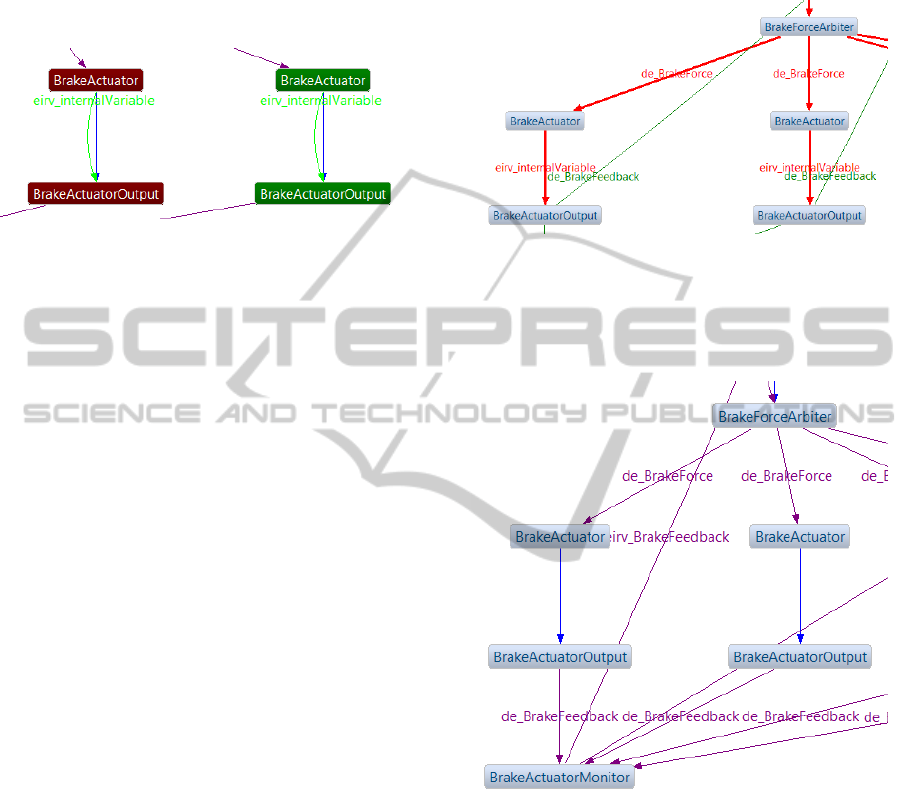
Figure 5 shows some RE instances of the BbW
example and their status (graph colors) after initially
running the analysis. Beginning with this, a software
engineer can iteratively fix the problematic dependen-
cies by imposing inevitable constraints. The analysis
is automatically rerun after each modification, so that
it is easy to track its effects. The final goal is to ob-
tain a cycle-free and therefore validated model whose
possible execution sequences do not lead to data in-
consistencies. Figure 6 partially shows such a model.
Figure 5: This cropped screenshot shows the results after
the first run of the analysis. The dependencies’ (graphs’)
colors indicate the respective dependency type whereas the
annotated text shows the affected variables’ names. Red
lines point to problematic cycles that need to be fixed man-
ually by the software engineer.
Figure 6: Having validated the model with the help of ACs
(purple) and EOCs (blue), the analysis should not find any
further problems as shown in this cropped screenshot. The
model is now properly prepared for searching a good map-
ping of RE instances to IEUs.
6 CONCLUSIONS
Since the migration to software that runs on mul-
tiple IEUs tremendously increases the architectural
complexity, our overall goal was to effectively de-
termine ambiguities and inconsistencies in systems
modeled with AUTOSAR capabilities and to support
their proper resolution.
We achieved this by utilizing existing modeling
MODELSWARD2014-InternationalConferenceonModel-DrivenEngineeringandSoftwareDevelopment
280

capabilities and combine them with results from re-
search activities, enabling us to immediately make
use of it. This is carried out by implementing our
Artop-based tool as an Eclipse plug-in that runs its
analyses directly on AUTOSAR models and writes
back the results and changes performed. More pre-
cisely, the tool executes a data dependency analysis
on AUTOSAR models, automatically imposes appar-
ent (simple) constraints on the RE instances, high-
lights existing cycle-related conflicts and supports the
software engineer resolving these problems. As the
validation of the models ensures that data is pro-
duced (written) by an RE instance before it is con-
sumed (read) by another one, the tool continues with
the determining suitable sets of virtually isolated RE
instances. This is done in order to support a sys-
tem’s parallelization by third party tools that might,
e.g., search for an advantageous task to IEU mapping.
Thus, other tools do not need to repeat our analysis
and are taking advantage of our work.
Our future research will address the significance
of dependency analyses as well as the support of par-
allelization on higher levels of abstraction.
REFERENCES
Artop Group (2012). AUTOSAR Tool Platform.
https://www.artop.org/.(accessed on July 20th, 2013).
AUTOSAR (2011). Specification of Timing Extensions.
AUTOSAR (2013). AUTOSAR Methodology.
Bohn, M., Schneider, J., Eltges, C., and R
¨
oßger, R. (2011).
Migration von AUTOSAR-basierten Echtzeitanwen-
dungen auf Multicore-Systeme. In Workshop: En-
twicklung zuverl
¨
assiger Software-Systeme (Stuttgart,
Germany).
Deubzer, M., Hobelsberger, M., Mottok, J., Schiller, F.,
Dumke, R., Siegle, M., Margull, U., Niemetz, M., and
Wirrer, G. (2010). Modeling and Simulation of Em-
bedded Real-Time Multicore Systems. In Proceedings
of the 3rd Embedded Software Engineering Congress,
pages 228–241.
Eclipse Foundation (2009). Eclipse Modeling Framework
Project. http://eclipse.org/modeling/emf/, accessed on
July 15th, 2013).
Eißenl
¨
offel, T. (2012). Embedded-Software entwickeln.
dpunkt.
Gehrke, M., Nawratil, P., Niggemann, O., Sch
¨
afer, W., and
Hirsch, M. (2006). Scenario-based verification of au-
tomotive software systems. In MBEES, pages 35–42.
Gleim, U. and Sch
¨
ule, T. (2012). Multicore-Software.
dpunkt.
G
¨
otz, M., Roser, S., Lautenbacher, F., and Bauer, B. (2009).
Token analysis of graph-oriented process models. In
Enterprise Distributed Object Computing Conference
Workshops, 2009. EDOCW 2009. 13th, pages 15–24.
Johnson, R., Pearson, D., and Pingali, K. (1994). The pro-
gram structure tree: Computing control regions in lin-
ear time. In ACM SigPlan Notices, volume 29, pages
171–185. ACM.
Multicore, A. (2011). Relevanz eines Multicore-
¨
Okosystems f
¨
ur k
¨
unftige Embedded Systems: Po-
sitionspapier zur Bedeutung, Bestandsaufnahme und
Potentialermittlung der Multicore-Technologie f
¨
ur
den Industrie-und Forschungsstandort Deutschland.
Ottenstein, K. J. and Ottenstein, L. M. (1984). The Program
Dependence Graph in a Software Development Envi-
ronment. In ACM Sigplan Notices, volume 19, pages
177–184.
Padberg, F. and Denninger, O. (2013). Multicore-
Softwarefehler im Visier: Automatische Fehlererken-
nung in Entw
¨
urfen paralleler Programme. OBJEKT-
spektrum, Ausgabe 01/2013, 20(1):72–76.
Patterson, D. (2010). The trouble with multi-core. Spec-
trum, IEEE, 47(7):28–32.
Saad, C. (2009). Model Analysis Framework.
http:// www.informatik.uni-augsburg.de/en/chairs/
swt/ds/projects/mde/maf/. (accessed on July 20th,
2013).
Saad, C. and Bauer, B. (2013). Data-flow based
Model Analysis and its Applications. (accepted
for ACM/IEEE 16th International Conference on
Model Driven Engineering Languages and Systems,
29 September 2013 through 4 October 2013, Miami,
USA).
Sch
¨
auffele, J. and Zurawka, T. (2010). Automotive Software
Engineering. Springer DE.
Shih, C., Wu, C.-T., Lin, C.-Y., Hsiung, P.-A., Hsueh,
N.-L., Chang, C.-H., Koong, C.-S., and Chu, W. C.
(2009). A model-driven multicore software develop-
ment environment for embedded system. In Computer
Software and Applications Conference, 2009. COMP-
SAC’09. 33rd Annual IEEE International, volume 2,
pages 261–268. IEEE.
Sodan, A. C., Machina, J., Deshmeh, A., Macnaughton, K.,
and Esbaugh, B. (2010). Parallelism via multithreaded
and multicore CPUs. Computer, 43(3):24–32.
Sutter, H. (2005). The Free Lunch Is Over: A Fundamen-
tal Turn Toward Concurrency in Software. Dr. Dobbs
Journal, 30(3):202–210.
TIMMO (2007). Timing Model. http://
www.itea2.org/project/index/view?project=170.
(accessed on July 18th, 2013).
TIMMO-2-USE (2010). TIMMO Braking System.
http:// www.timmo-2-use.org/. (accessed on July 18th,
2013).
Tip, F. (1995). A Survey of Program Slicing Techniques.
Journal of programming languages, 3(3):121–189.
Wirbel, L. (2011). Embedded Multicore Goes Mainstream.
http://www.designnews.com/author.asp?section id=
1386&doc id=231676. (accessed on July 15th, 2013).
AnalysisandValidationofAUTOSARModels
281
