
A Graph-based Algorithm for Three-way Merging of Ordered
Collections in EMF Models
Felix Schw
¨
agerl, Sabrina Uhrig and Bernhard Westfechtel
Applied Computer Science 1, University of Bayreuth, Universit
¨
atsstr. 30, 95440 Bayreuth, Germany
Keywords:
EMF Models, Model Merging, Graph Algorithms.
Abstract:
Version control for models is not yet supported in an adequate way. In this paper, we address three-way
merging of model versions. Based on a common base version b, two alternative versions a
1
and a
2
were
developed by copying and modifying the base version. To reconcile these changes, a merged version m is
to be created as a common successor of a
1
and a
2
. We present a graph algorithm to solve an important
subproblem which occurs in three-way model merging: merging of (linearly) ordered collections. To create
the merged version, a generalized topological sort is performed. Conflicts occur if the order of elements
cannot be deduced automatically; these conflicts are resolved either interactively or by default rules. We have
implemented the merge algorithm in our tool BTMerge, which performs a consistency-preserving merge of
versions of EMF models being instances of arbitrary Ecore models. By taking arbitrary move operations into
account, the algorithm considerably goes beyond the functionality of contemporary merge tools which are
based on common subsequences and thus cannot adequately handle move operations.
1 INTRODUCTION
Model-Driven Software Engineering (MDSE) (Stahl
and Voelter, 2006) denotes a software engineering
process which is driven by the development of high-
level models being expressed in well-defined model-
ing languages. While MDSE is an active research area
and more and more is making its way into industrial
practice, several obstacles still impede its application.
In particular, developing models in a team over a large
period requires sophisticated version control: Each
model evolves into multiple versions. Version control
tools need to store these models, compute differences,
and merge model versions which have been created
concurrently on different branches by different soft-
ware engineers.
Traditional version control tools such as Subver-
sion (Collins-Sussman et al., 2004) or CVS (Vesper-
man, 2006) operate on text files. Even if models
are stored as text files (e.g., XMI documents), apply-
ing traditional version control tools to models suffers
from serious limitations, particularly concerning the
comparison and merging of model versions (F
¨
ortsch
and Westfechtel, 2007). Thus, tools for comparing
and merging models which take the syntax and/or se-
mantics of models into account are urgently needed.
In contrast to text-based tools, model-based tools op-
erate on the representation of models as sets of inter-
connected model elements. For comparing models, a
variety of algorithms has been proposed and imple-
mented (Kelter et al., 2005; Mehra et al., 2005; Xing
and Stroulia, 2005; van den Brand et al., 2010), in-
cluding e.g. the well known EMF Compare tool (Brun
and Pierantonio, 2008). Likewise, quite a number of
model-based merge tools have been developed (Ala-
nen and Porres, 2003; Altmanninger et al., 2009; Alt-
manninger et al., 2010; Koegel et al., 2010; Taentzer
et al., 2012; Schw
¨
agerl et al., 2013b).
In this paper, we focus on three-way merging of
model versions (Figure 1). Based on a common base
version b, two alternative versions a
1
and a
2
were de-
veloped by copying and modifying the base version.
To reconcile the changes on both branches, a merged
version m is to be created as a common successor of
a
1
and a
2
. Three-way merging is required e.g. for op-
timistic version control as supported by version con-
trol tools such as Subversion (Collins-Sussman et al.,
2004) or CVS (Vesperman, 2006): Different software
engineers may concurrently create different succes-
sors of the same base version without being delayed
by locks on the base version. Later on, they recon-
cile their work by three-way merging such that non-
conflicting changes are combined automatically and
conflicts are detected and resolved.
41
Schwägerl F., Uhrig S. and Westfechtel B..
A Graph-based Algorithm for Three-way Merging of Ordered Collections in EMF Models.
DOI: 10.5220/0004702100410054
In Proceedings of the 2nd International Conference on Model-Driven Engineering and Software Development (MODELSWARD-2014), pages 41-54
ISBN: 978-989-758-007-9
Copyright
c
2014 SCITEPRESS (Science and Technology Publications, Lda.)

m
a
1
c
1
c
2
b
a
2
Figure 1: Three-way merging.
For three-way merging of models, we have de-
veloped the tool BTMerge (Schw
¨
agerl et al., 2013a;
Schw
¨
agerl et al., 2013b) which is based on the the-
oretical foundations presented in (Westfechtel, 2010;
Westfechtel, 2012) and is characterized by the follow-
ing features: First, BTMerge is a model-based tool
which internally relies on a graph representation of
the input models to be merged. Second, the tool may
be applied to any EMF model, regardless of the un-
derlying Ecore model. Thus, BTMerge covers a large
set of models, obviating the need for a specific merge
tool for each model type. Third, BTMerge preserves
consistency: Being supplied with input models which
are consistent instances of a common Ecore model,
BTMerge constructs a consistent merged model.
The current paper deals with an important sub-
problem which occurs in three-way model merging:
merging of (linearly) ordered collections. Collections
are contained in virtually any model; consider e.g.
parameters of operations or structural and behavioral
features of classes in Ecore models (which are model
instances, too). In the case of ordered collections, a
three-way merge algorithm has to consider not only
insertions and deletions, but also move operations. If
the elements of ordered collections are allowed to be
moved in arbitrary ways, it is far from trivial to de-
duce their mutual order in the merged collection.
After clarifying the contribution of our paper, Sec-
tion 3 provides relevant foundations. In Section 4,
we introduce a motivating example problem and de-
rive an expected solution. The description of our al-
gorithm follows in Section 5, which also contains an
analysis of its complexity. Furthermore, we explain
how the algorithm handles the example. Section 6
describes the integration of the algorithm with BT-
Merge. Section 7 covers related work and includes
a comparison based on a small set of examples; Sec-
tion 8 concludes the paper.
2 CONTRIBUTION
In this paper, we present an algorithm for merging
ordered collections in EMF models created in the
Eclipse Modeling Framework (Steinberg et al., 2009).
For each ordered collection to be constructed in
the merged version, a graph is built whose vertices
and edges correspond to the elements and their or-
dering relationships, respectively. In general, this
intermediate graph does not represent a linear order
and may even contain cycles (in the case of conflict-
ing move operations). To create the merged version,
a generalized topological sort (GTS) is performed.
Conflicts occur if the order of elements cannot be de-
duced automatically. In this case, either the end user
has to perform a decision (interactive merge), or a de-
fault decision has to be applied (batch merge). Due to
the generalized topological sort, we refer to our con-
tributed algorithm as the GTS algorithm subsequently.
The problem of merging linear data structures has
been studied for different kinds of artifacts such as
models (the focus of this paper), text files, or XML
documents (Lindholm, 2004; Khanna et al., 2007;
Koegel et al., 2010; Brun and Pierantonio, 2008;
Taentzer et al., 2012; Westfechtel, 2012). The GTS
algorithm is distinguished from related approaches by
the following properties:
P1 State-based Approach. Our algorithm is exclu-
sively state-based. It neither relies on change logs,
nor does it reconstruct change sequences. There-
fore, the produced result depends neither on the
actual editing history nor on the way in which
changes are reconstructed.
P2 Separation of Matching and Merging. The
merge algorithm relies on a matching which iden-
tifies corresponding elements of the input ver-
sions. Any algorithm for matching may be used
without affecting the merge algorithm.
P3 Uniqueness of Elements. When merging unique
ordered collections (ordered sets), the algorithm
guarantees that the merge result will preserve
uniqueness; each element will occur only once.
P4 Consistent Propagation of Insertions and Dele-
tions. By abstracting from the order of the merged
collection, the same collection will be obtained
which would be produced by merging the respec-
tive unordered collections. Thus, if an element
was inserted/deleted on one branch, it will be in-
serted into/removed from the merged collection.
P5 Support of Move Operations. There is no
constraint concerning the relative ordering of
matched elements. Thus, when the alternative ver-
sions are created from the common base version,
elements may be moved in arbitrary ways.
P6 Global Reasoning. In contrast to performing
merge decisions locally, the GTS algorithm con-
structs a global data structure. In this way, con-
flicts may be recognized which may go unnoticed
MODELSWARD2014-InternationalConferenceonModel-DrivenEngineeringandSoftwareDevelopment
42

when local merge rules are applied without any
coordination.
P7 Transitive Relationships. Our merge algorithm
considers not only immediate neighbors of ele-
ments, but in addition takes transitive ordering re-
lationships into account. In this way, more intu-
itive merge results may be obtained.
P8 Unified Two- and Three-way Merging. In ad-
dition to three-way merging, the merge algorithm
covers two-way merging, as well. Two-way merg-
ing may be applied if the base version is not avail-
able. In this case, each difference requires a user
decision
1
.
3 FOUNDATIONS
In the Eclipse Modeling Framework (EMF) (Stein-
berg et al., 2009), Ecore can be used to define meta-
models. In the current section, we make a minimal set
of assumptions necessary to handle EMF models, par-
ticularly concerning multi-valued structural features.
3.1 EMF Models
An EMF model is a set of objects (instances of
EObject), each of which consists of values for struc-
tural features defined in the meta-model. Structural
features are divided into attributes, whose values are
atomic, and references, which are used to intercon-
nect objects by links. Depending on their multiplici-
ties, structural features are either single-valued (upper
bound of 1) or multi-valued (upper bound greater than
1, realized as collections).
3.2 Collections in EMF
Four types of collections are distinguished by the
properties ordered and unique of their corresponding
structural feature. A set is a unique collection which
contains each of its elements exactly once; a bag al-
lows for multiple occurrences of its elements. Unique
and non-unique ordered collections are called ordered
sets and sequences, respectively.
In EMF, only attribute values can be stored in
bags; the values of references must be unique. For
the realization of multi-valued features, EMF uses
ordered collections (instances of EList), regardless
of whether the corresponding structural feature is or-
dered or not.
1
Due to the lack of space, however, we will confine our
representation to the use case of three-way merging.
3.3 Matchings
Before alternative versions of a collection can be
merged with respect to a common base version, it is
necessary to identify their commonalities and differ-
ences. In state-based approaches, this is achieved by
calculating matchings. A matching is a binary rela-
tion between the elements of two collections such that
(C1) each element is matched at most once and (C2)
only equal elements are matched. Two cases have to
be distinguished:
• In the case of ordered sets, the calculation of the
matching is trivial since it may simply be induced
from their elements. In addition to C1 and C2, the
induced matching is maximal, i.e., (C3) all equal
elements are matched.
• In the case of sequences, a match algorithm is re-
quired to calculate a matching. Match algorithms
on sequences do not necessarily satisfy condition
C3, i.e., it may happen that equal elements remain
unmatched.
An order-preserving matching preserves the order
of elements (C4), i.e., if two elements are matched,
they appear in the same (transitive) order in both
collections. For example, an algorithm computing
the longest common subsequence (Hunt and Szyman-
ski, 1977) returns an order-preserving matching. In
general, the induced matching on two ordered sets
may not be order-preserving. Furthermore, an order-
preserving matching on sequences may leave equal
elements unmatched, i.e., in general, the matching
does not satisfy condition C3.
3.4 Merging
As explained above, collections may be classified
into four categories (sets, bags, ordered sets, and se-
quences). However, all of these cases may be covered
by a single algorithm:
• In EMF, all collections are stored as lists even if
the underlying Ecore model designates the respec-
tive structural feature as unordered. Likewise, our
GTS algorithm always considers the order of the
collections to be merged. Even when the order is
irrelevant, it makes sense to preserve it whenever
possible as it may affect the external representa-
tion of the model and thus the model’s interpreta-
tion by the user.
• If an element has multiple occurrences in a collec-
tion (which can only be the case for non-unique
multi-valued attributes), the mapping refers to the
AGraph-basedAlgorithmforThree-wayMergingofOrderedCollectionsinEMFModels
43

occurrences of elements rather than to the ele-
ments themselves. Therefore, we can handle bags
analogously to sets.
In our work, matching is clearly separated from
merging. The merge algorithm assumes a matching
calculated by some match algorithm. In this way, the
match algorithm may be replaced without affecting
the merge algorithm. However, as far as ordered sets
are concerned, the merge algorithm assumes the in-
duced matching (which is trivial to compute). Other-
wise, it cannot be guaranteed that merging of ordered
sets delivers an ordered set. For example, if an el-
ement is inserted on both branches and remains un-
matched, it would be inserted twice.
From the input collections and their pair-wise
matchings, the set of elements of the merged collec-
tion may be calculated as follows:
1. If an element occurs in both a
1
and a
2
, it is in-
serted into m.
2. If an element occurs in either a
1
or a
2
and is con-
tained in the base b, it is not included into m.
3. If an element occurs in either a
1
or a
2
and not in
b, it is inserted into m.
However, determining the order of elements is
much more difficult (see subsequent sections).
4 MOTIVATING EXAMPLE
4.1 Example
The following small example serves as an introduc-
tion to the underlying ideas of the merge algorithm
and will be revisited after the algorithm has been ex-
plained in detail. For reasons of space, we chose an
abstract example, where same letters represent corre-
sponding elements. We have a base version b of an
ordered set, that has evolved into two different ver-
sions a
1
and a
2
as stated here:
b = T KQNFBP,
a
1
= KQT NJPFS,
a
2
= T KMNPJFX.
The author of the first modified version a
1
has
reordered the first three elements, inserted J and S,
deleted B and rearranged P and F. The second ver-
sion a
2
has been modified as follows: the elements Q
and B have been deleted, and M has been inserted. F
and P have also been rearranged. The second author
also inserted J, but at a different position. Finally,
he/she inserted an element X at the last position.
4.2 The expected Merge Result
In order to consider the changes of both authors in
a common version, the merge algorithm comes into
play, but what is the expected result?
We expect the merge algorithm to make simple
decisions on its own and let the user resolve only
contradictory changes. The merge algorithm should
prevent the user from generating a solution that may
not be derived by the merge rules for sets with re-
spect to contained elements (Section 3.4). Further-
more, the order of the elements has to be considered.
This does not only hold for direct relations, but also
for indirect/transitive relations. Transitive relations in
the base version should be preserved unless they were
destroyed in either of the alternative versions. In this
way, a more intuitive merge result is produced.
So let’s have a look at our example. The reorder-
ing of T and K realized by the first author should be
preserved, i.e., we expect m to start with K. Q has
to be deleted because it is deleted in a
2
. M has been
inserted by the second user after K and should be in-
cluded into the merged version. Likewise, T should
be included because it is contained in all input ver-
sions. Since M has been inserted after K in a
2
and T
has been moved after K in a
2
(recall that Q is deleted),
there is a conflict concerning the ordering of T and
M, i.e., both elements may be arranged in arbitrary
order. Furthermore, it is clear that T , K and M have
to be placed before N. Next, we would like to have
B deleted in the merged version as it has been deleted
in both versions. As J has been inserted in both ver-
sions but at different positions, the decision whether J
is positioned before or after P has to be left to the user.
Both elements have to be placed before F. The inser-
tion of S and X at the last position is contradictory and
can only be resolved by the user.
In sum, we get a total of 8 different plausible solu-
tions. These solutions can be expressed by the follow-
ing regular-like expression including 3 user decisions:
m = K{T M}N{JP}F{XS}.
The operator {.} stands for a cluster of elements;
its operands may be arranged in an arbitrary order
2
.
2
The fact that our example allows for 8 plausible solu-
tions reflects that in many cases, the existence of a single
optimal solution is arguable as the expected result may de-
pend on the specific application. In (Uhrig and Schw
¨
agerl,
2013), we have discussed a similar problem in the context
of model matching.
MODELSWARD2014-InternationalConferenceonModel-DrivenEngineeringandSoftwareDevelopment
44

5 THE GTS ALGORITHM
In this section, we present the generalized topologi-
cal sort algorithm for merging ordered collections. It
considers different versions as linear graphs. The el-
ements of the collections are represented by vertices
and the vertices of direct successors are connected by
directed edges such that every vertex has an edge to
its successor. The graph representations of these three
ordered collections are combined into an initial merge
graph which is traversed in order to identify a linear
order of the elements. Due to conflicting changes, the
graph usually contains cycles and/or alternative paths.
With the help of a generalized topological sort, the
traversal is executed automatically if possible. In case
there are multiple candidates for the next step, the user
is asked to decide.
5.1 Definitions
Let S denote a set of n elements. An ordered set is
a bijective function
~
S : S → {1..n}.
~
S(i) denotes the
element of
~
S at position i. Furthermore, let S
0
⊆ S.
Then,
~
S|
S
0
denotes the restriction of
~
S onto the ele-
ments of S
0
, i.e., the ordered set which is obtained by
removing all elements not contained in S
0
. A parti-
tion π of a set S is a set of sets S
1
.. .S
m
such that
S
1
∪ . .. ∪ S
m
= S and S
i
∩ S
j
=
/
0(i 6= j). Finally, a di-
rected graph g = (V, E) is a pair consisting of a vertex
set V = {v
1
,. .. ,v
n
} and an edge set E ⊆ V ×V .
Our algorithm is supplied with three ordered sets
~
V
b
,
~
V
1
, and
~
V
2
. Equal elements are identified by the
matchings having been calculated before the merge
algorithm is executed. The output of the GTS algo-
rithm will be an ordered set
~
V
m
. The algorithm uses
four graphs g
j
= (V
j
,E
j
), j ∈ {b, 1,2, m} as auxiliary
data structures. The merge graph g
m
is transformed
step by step until it represents an ordered set which is
finally converted into the output
~
V
m
.
The GTS algorithm contains potentially non-
deterministic operations, which are underlined in the
description below. We assume that either the user is
involved to make a decision, or that a batch-like pro-
cedure resolves non-determinism.
5.2 Algorithm in Pseudo-Code
1. Calculate the unordered set of merged vertices:
V
m
:= (V
1
∪V
2
) \ ((V
b
\V
1
) ∪ (V
b
\V
2
)).
2. Modify the inputs in order to exclude deleted ele-
ments:
~
V
j
:=
~
V
j
|
V
m
, j ∈ {1, 2,b}.
Furthermore, initialize the output
~
V
m
:=
/
0.
3. Construct edge sets for the input versions. Pairs
of vertices that follow each other in the modified
ordered sets are connected by an edge:
E
j
:= {(
~
V
j
(1),
~
V
j
(2)),. .. ,
(
~
V
j
(n
j
− 1),
~
V
j
(n
j
))}, j ∈ {1, 2,b}.
4. Calculate the unordered set E
m
of semi-
transitively merged edges, which is defined
as the union of E
1
and E
2
, excluding edges that
“represent an immediate order that has been
deleted transitively on the other branch”
3
:
E
m
:= (E
1
∪ E
2
) \ ((E
+
b
\ E
+
1
) ∪ (E
+
b
\ E
+
2
)).
5. For each vertex v
i
inside V
m
that has no incoming
edge, find the closest common predecessor if pos-
sible, i.e. a vertex v
ccp
that has a minimal distance
to v
i
in both V
1
and V
2
. If v
ccp
exists, add the edge
(v
ccp
,v
i
) to V
m
.
6. For each vertex v
i
inside V
m
that has no outgoing
edge, find the closest common successor if possi-
ble, i.e. a vertex v
ccs
that has a minimal distance
from v
i
in both V
1
and V
2
. If v
ccs
exists, add the
edge (v
i
,v
ccs
) to V
m
.
7. Identify the strongly connected components of
g
m
4
. This part of the algorithm is described in de-
tail in the Appendix. As a result, we obtain a par-
tition π
m
= {C
m1
,. .. ,C
mk
} of the set of vertices
V
m
.
8. Perform a user-aided topological sort (Sedgewick
and Schidlowsky, 2003, Chapter 19.6) based on
π
m
. While V
m
6=
/
0, perform the following steps
(for more details, see Appendix):
(a) If the component selected in the previous itera-
tion is not empty, continue with it. Else select a
new non-empty strongly connected component
C
m j
from π
m
that contains no vertex with an in-
coming edge from outside.
(b) Select v
i
as one of the vertices inside C
m j
. If
possible, restrict the candidate set to vertices
that are ordered first in one of the input se-
quences
~
V
1
or
~
V
2
, and/or to successors of the
vertex selected in the previous iteration.
(c) Append v
i
to the end of
~
V
m
.
(d) Remove v
i
and all of its incoming and outgoing
edges from g
m
.
9. The resulting ordered set is
~
V
m
.
3
E
+
j
denotes the transitive closure over the edge set E
j
.
4
A strongly connected component of a graph is a set of
vertices where each pair of vertices is connected by a di-
rected path. The algorithm used for the identification of
strongly connected components was proposed by Kosaraju
(Sedgewick and Schidlowsky, 2003, Chapter 19.8).
AGraph-basedAlgorithmforThree-wayMergingofOrderedCollectionsinEMFModels
45

5.3 Example Revisited
Before analyzing the particular steps of the GTS algo-
rithm in general, let us return to our running example
introduced in Section 4 and apply the algorithm to it.
The (ordered) input sets of vertices were given as:
~
V
b
= T KQNFBP,
~
V
1
= KQT NJPFS,
~
V
2
= T KMNPJFX.
The application of the vertex set rule in step 1 gives
us the following unordered result set of vertices:
V
m
= {K, T, N,J, P, F, S,M, X}.
The restriction of the inputs to V
m
in step 2 results in
the following modified inputs:
~
V
b
= T KNFP,
~
V
1
= KT NJPFS,
~
V
2
= T KMNPJFX.
Next, the creation of edges for succeeding elements
in step 3 results in the following edge sets:
E
b
= {(T,K), (K, N),(N,F), (F, P)},
E
1
= {(K,T ), (T, N), (N, J), (J, P),(P,F),
(F, S)},
E
2
= {(T,K), (K, M), (M, N),(N, P),(P, J),
(J, F),(F, X)}.
In step 4, the edge set E
m
is created using the semi-
transitive merge rule. For each edge contained in E
1
or E
2
, we have to check if it has been “deleted transi-
tively” in the opposite version. In this example, this is
only the case for the edge (T, K): It exists in E
b
and
E
2
, but not (transitively) in E
1
. All the other edges
from E
1
and E
2
are added to E
m
. The resulting edge
set is:
E
m
= {(K,T ), (T, N), (N, J), (J, P),(P,F), (F,S),
(K, M), (M, N),(N,P), (P, J), (J, F), (F, X)}.
After step 4, g
m
can be visualized as follows:
K T N
M P
J
F
X
S
During steps 5 and 6, additional transitive edges
(closest common predecessors and successors) are
added in general. In this example, these steps do not
have any effect because K and S/X have no common
predecessor/successor in E
1
and E
2
.
Step 7 identifies the strongly connected compo-
nents of g
m
. In this example, there is only one com-
ponent that contains two or more vertices: the cycle
{J, P}.
π
m
= {{K}, {T }, {N}, {J, P},{F}, {S},{M},{X }}.
In step 8, a user-aided topological sort is performed
on S
m
as described by the following increments:
1. {K} is the only strong component without incom-
ing edge from outside. The vertex K is selected
automatically and removed from g
m
. The current
result is
~
V
m
= K.
2. Either {T } or {M} can be chosen as the next com-
ponent. Depending on the user’s choice, either T
or M is added to the result.
3. The component that has not been chosen in the
previous increment is selected next deterministi-
cally. Using the notation introduced at the end of
Section 4.2, we may represent the set of possible
results processed so far:
~
V
m
= K{T M}
5
.
4. N is selected deterministically. Now,
~
V
m
= K{T M}N.
The current graph g
m
can be visualized as follows:
P
J
F
X
S
5. The component {J, P} is chosen next. Both can-
didates, P and J appear first in one alternative (J
in V
1
, P in V
2
) and are direct successors of the pre-
viously processed N. Consequently, the decision
is up to the user.
6. The selected component still contains a vertex,
which is added deterministically:
~
V
m
= K{T M}N{JP}.
7. F is selected deterministically:
~
V
m
= K{T M}N{JP}F.
8. Either {S} or {X} can be chosen as next compo-
nent. Depending on the user’s choice, either S or
X is added to
~
V
m
.
9. The last vertex (X or S) is added to
~
V
m
determinis-
tically. After that, g
m
is an empty graph. Coincid-
ing with the expected result derived in Section 4.2,
the overall result is:
~
V
m
= K{T M}N{JP}F{XS}.
5
Note that a single run of the algorithm produces just
one result, ordering either T before M or vice versa.
MODELSWARD2014-InternationalConferenceonModel-DrivenEngineeringandSoftwareDevelopment
46

5.4 Properties
Particular properties of the GTS algorithm have al-
ready been claimed in the introduction (P1 until P8).
Now we revisit the algorithm in order to show which
properties can be asserted to respective (intermedi-
ate) results. The algorithm is divided into three major
parts: vertex set calculation, which takes place in step
1, edge set calculation, which is performed by steps 2
until 6, and graph traversal, beginning with step 7.
Vertex Set Calculation: In step 1, the set of ele-
ments to be contained by the resulting sequence
is fixed. It consists of a union of the vertex sets V
1
and V
2
, excluding vertices that have been deleted
in the first (V
b
\V
1
) or second (V
b
\V
2
) alternative
version. By the application of the given set op-
erations, it is impossible to produce a result that
contains several instances of a matched element,
so the uniqueness of elements property is fulfilled
(P3). Furthermore, our algorithm produces a re-
sult that is consistent with the reasoning for three-
way merging sets of elements described at the end
of Section 3.4. The set of vertices cannot be mod-
ified by later steps; consequently, the propagation
of insertions and deletions is consistent (P4).
Edge Set Calculation: Steps 2 and 3 are necessary
to construct (linear) graphs for the input se-
quences. The properties of global reasoning (P6)
and transitive relationships (P7) require that the
merged edge set does not only include edges that
emerge from direct, but from transitive relation-
ships encoded in paths inside E
1
and E
2
. The
GTS algorithm considers this fact by a twofold
strategy. Step 4 ensures that non-contradictory
transitive information that is already stored in di-
rect edges of the alternative versions is preserved.
Nevertheless, it is not possible to maintain each
possible transitive path this way. In some cases,
a “transitive deletion” of an edge destroys a path
that expresses another valid relationship between
two elements. Therefore, in steps 5 and 6, addi-
tional relationships are added to vertices that have
an undetermined transitive predecessor/successor
set.
In step 4, the merged edge set E
m
is calculated
by a semi-transitive merging rule. As already de-
scribed in the pseudo-code, the intuition behind
this rule is to delete an “immediate order that
has been deleted transitively on the other branch”.
While immediate orders are expressed by edges in
E
1
and E
2
, transitive deletions can be expressed
by (E
+
b
\ E
+
2
) or (E
+
b
\ E
+
1
), respectively. For the
merged edge set, the condition (E
1
∩ E
2
) ⊆ E
m
⊆
(E
1
∪ E
2
)) holds.
6
After step 4, there might be additional non-
contradictory transitive relationships expressed in
the input versions which are not yet considered
in E
m
, and neither contained in E
1
∪ E
2
. Due to
cross-over moves, g
m
might contain vertices that
have no predecessor or successor, even if there ex-
ist one or more common predecessors or succes-
sors in g
1
and g
2
. The basic idea behind steps 5
and 6 is to reconstruct these (so far ignored) rela-
tionships by finding the closest common predeces-
sor or successor. By including an additional edge
from/to that identified vertex, a subset of E
+
1
∩E
+
2
is included that expresses exactly the missing in-
formation.
7
Graph Traversal: After step 6, the transitive clo-
sure over the edge set E
m
contains all non-
contradictory transitive relations from E
1
and E
2
.
Based on this graph, a linear order has to be de-
rived in the subsequent steps. As described above,
this is performed by means of a topological sort.
Due to the support of arbitrary move operations
(P5), g
m
may contain cycles, particularly in case
of cross-over moves. Unfortunately, cycles inhibit
the application of a topological sort. To over-
come this problem, the topological sort in step 8
is not performed on the original graph, but on its
strongly connected components which are calcu-
lated in advance by step 7: Cycles are virtually
replaced by atomic vertices. When the topologi-
cal sort enters a cycle, the order of its contained
elements needs to be derived in a reasonable way.
Sub-step 8b of the GTS algorithm makes sure that
the order in which the vertices of a cycle are tra-
versed is consistent with the order of one of the al-
ternative input sequences
~
V
1
and
~
V
2
. At the same
time, step 8a makes sure that a cycle is only left
after all of its vertices have been processed.
8
6
In the running example, the deletion of the edge (T,K)
is necessary because otherwise, the user could produce an
order that starts with T, which has obviously been removed
from the first position of the collection.
7
The running example does not require this step. As
a substitute, the interested reader may apply the GTS al-
gorithm to Example 2 from the Related Work section (Sec-
tion 7). Here, an additional transitive edge (A, D) is inserted
due to the interacting moves of B in
~
V
1
and D in
~
V
2
.
8
Again, the running example does not require this par-
ticular traversal strategy. In Example 1 from the Related
Work section, however, the absence of step 8b would allow
an order that does not contain the edge (A,C), which oc-
curs (transitively) in each of the three versions and should
definitely be preserved in the merged version.
AGraph-basedAlgorithmforThree-wayMergingofOrderedCollectionsinEMFModels
47
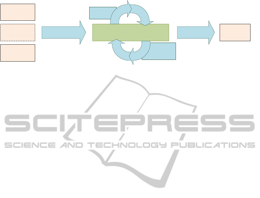
Conflict
Resolution
Merging
Left
Input
Ancestor
Input
Right
Input
BTMerge
Model
Export
Merged
Output
Construction
Figure 2: Our three-way model merge tool BTMerge, which includes an implementation of the GTS algorithm, decomposes
the merging problem into three phases.
5.5 Complexity
We outline an analysis of runtime complexity and
memory consumption for the GTS algorithm, pro-
ceeding step by step. The number n is considered
equal to |V
m
|, the number of vertices contained in
the resulting collection, which is equal or less than
|V
1
| + |V
2
|.
1. Provided that the presence of a vertex in a set can
be determined in constant time (e.g. by hashing),
we can compute V
m
in O(n). The same upper
bound obviously applies to memory consumption.
2. With the same assumption, we can compute and
store three restrictions of a maximum of 3n ele-
ments in O(n).
3. A maximum of 3(n − 1) edges are inserted. As-
suming that edges are stored in an adjacency list,
we have O(n) for both runtime complexity and
memory consumption.
4. The number of edges to be inserted into E
m
will
not exceed the upper bound 3(n − 1) and thus re-
quire O (n) of memory. The transitive closures
E
+
j
, however, would temporarily consume O(n
2
)
of memory. We can avoid this by rewriting the
merge rule as follows:
E
m
:= (E
1
\ (E
+
b
\ E
+
2
)) ∪ (E
2
\ (E
+
b
\ E
+
1
)).
The sets part of the union can be easily computed
by index comparisons, which are performed in
constant time. Consequently, we get O (n) for both
runtime and memory.
5. During step 5, vertices without predecessors are
traversed. In the worst case, finding a closest
common predecessor requires the traversal of all
n vertices of the input sequences V
1
and V
2
. The
number of vertices without predecessor has an up-
per bound of n, too, resulting in a complexity
of O (n
2
). However, the worst case will only be
reached if the number of cross-over move opera-
tions is close to n. A maximum of n new edges
are inserted, so the memory consumption is O(n).
6. Step 6 equals step 5 in runtime complexity and
memory consumption.
7. Using an adjacency list, the algorithm of Kosaraju
has a runtime of O (|V
m
| + |E
m
|) (Sedgewick and
Schidlowsky, 2003, Chapter 19.8). Here, an up-
per bound for |E
m
| is 3n, and so we get linear
runtime of O (n). Both the resulting strongly con-
nected components and the auxiliary search se-
quence will consume additional memory of O(n).
8. A topological sort can be performed in O(|V
m
| +
|E
m
|) (Sedgewick and Schidlowsky, 2003, Chap-
ter 19.6), which is O(n) in our special case (see
above). However, the selection of a vertex out of
the component has an additional worst-case com-
plexity of O(n) because the conditions (first ver-
tex in V
1
or V
2
, successor of previously inserted el-
ement) require traversing the vertex set of the cur-
rent component in each of the n iterations. In sum,
we have a computational complexity of O(n
2
).
Nevertheless, if no cycles occur in g
m
, selection
can be done in constant time, and runtime com-
plexity can be reduced to O(n). In any case, the
resulting sequence will consume O(n) of memory.
In sum, the GTS algorithm has a memory con-
sumption of O (n), which allows for three-way merg-
ing of large ordered collections. The computational
worst-case complexity is bounded to O(n
2
).
6 IMPLEMENTATION
We implemented the GTS algorithm for merging or-
dered collections as a generic standalone component
based on (but not restricted to) the Eclipse Modeling
Framework. The following explanations refer to the
integration of the component with our tool BTMerge
(Schw
¨
agerl et al., 2013b; Schw
¨
agerl et al., 2013a),
which performs a consistency-preserving three-way
merge of EMF models. As shown in Figure 2, model
merging is realized as a three-phase process. First,
MODELSWARD2014-InternationalConferenceonModel-DrivenEngineeringandSoftwareDevelopment
48

the merge model is created (construction) as a super-
imposition of the three input versions. For the identi-
fication of corresponding objects, we rely on a match
algorithm, e.g. EMF Compare (Brun and Pieranto-
nio, 2008). The identification of corresponding val-
ues inside unique collections is induced by equality
for attribute values, and by the object matching for
reference values, respectively. For non-unique collec-
tions, a heuristic sequence comparison is performed
that produces a maximal, but not necessarily an order-
preserving matching (see Section 3.3). The second
phase, merging, follows an incremental design. The
preliminary merge model is modified alternately by
the merge algorithm and the user; the merge algo-
rithm applies merge rules, which can be applied au-
tomatically, or stops in case of conflicts. These can in
turn be resolved by the user, who chooses one of the
proposed resolution methods. Only after all conflicts
have been resolved, the merge model is exported as
an EMF instance.
The user interface of the interactive merge tool,
called the resolution tool (cf. Fig. 3), allows the user
to communicate resolution decisions for specific con-
flicts during the second phase. A dedicated conflicts
view (not shown in the screenshot) outlines pending
merge decisions. The user can resolve a conflict by
means of a wizard that describes the consequences of
the proposed resolution methods. After resolution by
the user, the next merge increment is performed auto-
matically.
Figure 3: The resolution tool of BTMerge. The screenshot
depicts the situation after K has been inserted and the user
has to choose between T and M.
Steps 1 until 7 of the GTS algorithm are executed
during the construction phase, where an initial graph
g
m
is created for each multi-valued structural feature.
During merging, the respective graph is transformed
step by step in order to calculate the resulting ordered
Figure 4: A screenshot of a conflict wizard for the resolution
of an ordering conflict. The user is asked to select either T
or M as the preferred next value.
set
~
V
m
(step 8). For steps 8a/b, our tool provides
a conflict resolution wizard page that lets the user
choose the value he/she wants to appear previously
to all other selectable values (cf. screenshot Fig. 4).
The algorithm will continue with the selected v
i
until
the next conflict is detected. During export, the final
ordering described by
~
V
m
is considered when convert-
ing an ordered structural feature back into its EMF
representation.
The fact that EMF even stores the values of un-
ordered features in ordered lists led us to an alterna-
tive implementation that possibly skips the user inter-
action in steps 8a/b and selects an element by apply-
ing a default rule (left or right version) instead.
7 RELATED WORK
7.1 Related Approaches
Text-based merging has been used for long in ver-
sion control systems such as RCS (Tichy, 1985), CVS
(Vesperman, 2006), or Subversion (Collins-Sussman
et al., 2004). To this end, the tool diff3 (Khanna
et al., 2007) is used frequently. diff3 compares both
alternative versions to the base, relying on an al-
gorithm which computes a longest common subse-
quence (Hunt and Szymanski, 1977) of elements (text
lines). A longest common subsequence (LCS) is a
maximal matching among the elements of the sub-
sequences without cross-overs, i.e., two elements of
the longest common subsequence appear in the same
order in both sequences. Next, diff3 computes a se-
quence of stable and variable chunks (consecutive se-
quences of elements). A stable chunk is contained in
all three versions; a variable chunk has at least two
different versions. The merged version is constructed
from the sequence of chunks. A conflict occurs if a
chunk has three different versions. In the case of a
AGraph-basedAlgorithmforThree-wayMergingofOrderedCollectionsinEMFModels
49

non-interactive merge, as performed in version con-
trol systems, conflicting versions of chunks are writ-
ten to the merged version, and the user has to resolve
these conflicts post mortem.
3dm (Lindholm, 2004) is a tool for three-way
merging of XML documents. 3dm considers docu-
ments as ordered trees. A document is represented
by a set of facts for the contents of nodes and the
tree structure, the latter of which is expressed by pcs
triples (parent, child, successor). After a matching
phase, which identifies elements of different docu-
ments, the sets of facts are united. A conflict occurs if
the contents, the parent, predecessor, or successor of
a node are not unique. All facts from the base version
which are involved in conflicts are removed. If the re-
sulting set of facts is free of conflicts, a document is
created from the top to the bottom and (within lists)
from left to right. In (Lindholm, 2004), resolution of
conflicts among “new” facts is not considered.
Alanen and Porres (Alanen and Porres, 2003) de-
scribe algorithms for comparing and merging MOF
models. It is assumed that elements carry universally
unique identifiers. Elements from different model
versions are matched if their identifiers are equal. For
three-way merging, two directed deltas from the base
version to each of the alternative versions are calcu-
lated. In the case of ordered multi-valued features,
deltas are composed of insert and delete operations.
The merge algorithm merges the input deltas into a
single delta from the base to the merged version. Dur-
ing the merge, indices are updated if an operation
from the opposite delta is selected. A conflict oc-
curs if two elements are inserted at the same position.
A conflict is resolved by ordering the left before the
right element or vice versa. In the case of conflicts, all
possible deltas are computed, and a delta with mini-
mal length is returned.
As part of the version control system EMF Store,
a tool for three-way merging of EMF models is pro-
vided (Koegel et al., 2010). In EMF Store, all model
elements are identified by universally unique identi-
fiers. Furthermore, the model editor integrated with
EMF Store records change logs, which are stored in
the repository of the version control system. The
merge tool receives a base version and two operation
sequences, which are combined into a single sequence
from the base to the merged version. Changes to or-
dered collections are described in terms of insertions,
deletions, and move operations. Except for deletions
of the same element, change operations to the same
collection on different branches always conflict. To
resolve a conflict on an ordered collection, the user
may select either the left or the right version of the
whole collection.
EMF Compare (Brun and Pierantonio, 2008) is a
tool for comparing versions of EMF models. When
supplied with a base version and two alternative ver-
sions, EMF Compare may also be used for three-
way merging. To this end, both alternative versions
are compared to the base. From the resulting match
model, a difference model is derived which is com-
posed of deltas from the base version to the alterna-
tive versions. As in two-way merging, the user has
to decide for each change whether it is applied to the
opposite branch. In addition, EMF Compare detects
conflicting changes in the case of three-way merging.
EMF Compare may merge insertions and deletions on
ordered collections. The tool recognizes when the or-
der of elements has been changed. However, this re-
sults in an unspecific message concerning the whole
collection (“the order has changed”), and the user may
propagate the order to the opposite branch only as a
whole.
AMOR (Taentzer et al., 2012) provides a merge
tool for EMF models which follows EMF Compare’s
basic process of merging (see above). Moves are
recognized, but reduced to insertions and deletions,
which provide the foundation for merging. When
merging ordered collections, different types of con-
flicts are detected: (1) insertions of different elements
at the same index, (2) insertion of an element vs. dele-
tion of a predecessor/successor, or (3) deletions on
opposite branches with subsequent indices.
The algorithm presented in this paper constitutes
an improvement over the original algorithm for merg-
ing ordered collections that we proposed in (West-
fechtel, 2012) as a part of the EMF model merge algo-
rithm underlying a previous version of the BTMerge
tool. Like the GTS algorithm, the described algorithm
constructs three linear graphs representing the input
versions and combines them into a union graph. Next,
it removes vertices and edges having been deleted on
at least one branch, and constructs a linear order by
a series of graph transformations. These transforma-
tions aggregate mutually unrelated vertices as well as
vertices on cycles into clusters, whose elements may
then be serialized in any order. Therefore, we refer to
this algorithm as cluster algorithm below.
Compared to our GTS algorithm, the cluster al-
gorithm suffers from several limitations. In partic-
ular, since clusters may be serialized in any order,
an order of the elements may be constructed which
was not present in any input version. Furthermore,
the cluster algorithm may form clusters which are too
large. Instead of transforming the merge graph into a
sequence of clustered nodes, the GTS algorithm per-
forms a generalized topological sort; furthermore, it
takes transitive in addition to direct neighbor relation-
MODELSWARD2014-InternationalConferenceonModel-DrivenEngineeringandSoftwareDevelopment
50

Table 1: Expected and actual results for three example problems.
Example 1 Example 2 Example 3 (Running Example)
b ABC ABCDEF T KQNFBP
a
1
BAC ACDEFB KQT NJPFS
a
2
ACB ABDECF T KMNPJFX
m (expected) [BAC|ACB] ADECFB K{T M}N{JP}F{X S}
diff3 BA[C|CB] A[C|B]DECFB K[QT |M]N[JP|PJ]F[S|X]
Alanen and Porres BACB ADECFB K{T M}NJPJF{XS}
EMF Store 1.0.0 [BAC|ACB] [ACDEFB|ABDECF] [KQT NJPFS|T KMNPJFX]
EMF Compare [BAC|ACB] [ACDEFB|ABDECF] [T KM|T KQ|KQT |KMT ]N{JP}F{SX}
Cluster algorithm {ABC} A{BCDEF} K{T M}N{JPF}{SX}
GTS algorithm [BAC|ACB] ADECFB K{T M}N{JP}F{XS}
ships into account. Instead of transforming the merge
graph into a sequence, it performs a generalized topo-
logical sort. These differences result in considerably
improved behavior, as we will demonstrate below.
7.2 Comparison
Table 1 shows the results produced by applying most
of the tools/algorithms described above to a set of
three examples. The last row lists the outcomes of the
GTS algorithm presented in this paper. The results for
3dm were omitted; manual execution of all examples
results in conflicts, whose resolution is not described
in (Lindholm, 2004). AMOR was not included be-
cause the information given in (Taentzer et al., 2012)
does not suffice to perform a manual conflict resolu-
tion.
In the case of conflicts, multiple results may be
produced. These result sets are represented by regular
expressions, where {.} stands for an arbitrary permu-
tation of its operands and [.|.] indicates an exclusive
alternative.
In Example 1, B has been moved to the head and
the tail on different branches. Since only one of these
operations may be applied, we assume that a conflict
is reported and only one of these operations may be
applied. Depending of the conflict resolution, one
of BAC and ACB should be returned. In Example 2,
B has been moved to the tail in a
1
, and C has been
moved behind E in a
2
. These cross-over moves may
be merged without conflict, resulting in the output
ADECFB. Example 3 is our running example.
The GTS algorithm for ordered collections is the
only one which precisely produces the expected re-
sults in all examples.
diff3 does not support move operations, does not
guarantee the uniqueness of elements in the case of
ordered sets, and does not consistently propagate in-
sertions and deletions (properties P3, P4 and P5,
respectively; see Section 1). Conflicts are reported
even in Example 2 (non-conflicting moves), where
any conflict resolution results in a duplicate element
(B or C). In Example 3, Q may be part of the merged
version although it was deleted in a
2
.
The algorithm of Alanen and Porres does not sup-
port moves, either; however, it behaves differently
from diff3. In Example 1, B is deleted once and in-
serted twice, without reporting a conflict. In Exam-
ple 2, the correct result is delivered. In Example 3, J
is inserted twice (duplicate insertion of J, resulting in
the subsequence JPJ).
EMF Store does consider moves, but defines con-
flicts on a coarse-grained level. Since in all examples
both alternatives were modified, a conflict is raised in
each case (even in Example 2, where the moves could
be combined without conflict). The user may select
one of the inputs, but may not combine the change
operations.
With respect to re-orderings, EMF Compare fol-
lows a coarse-grained approach, as well. Therefore,
in Examples 1 and 2 EMF Compare merely reports
order changes, and the user may only establish the or-
der in one of the alternative versions. In particular, the
moves are not merged in Example 2. In Example 3, no
conflicts are reported. By applying all changes from
the base in different ways, a set of results may be pro-
duced which are as expected from N through to the
end. At the beginning, EMF Compare derives a sub-
stitution of Q by M rather a deletion of Q and insertion
of M. Thus, Q may be included into the merge result.
Furthermore, T may be ordered before K.
All three examples demonstrate different short-
comings of the cluster algorithm. In Example 1, the
cluster algorithm constructs the cycle A → C → B →
A and collapses this cycle into a cluster, whose el-
ements may arranged in any order. Clusters result in
loss of information and may allow unexpected permu-
tations such CAB (in both alternatives, A precedes C).
In Example 2, the algorithm constructs a cluster re-
sulting from the cycle B → D → E → C → F → B,
consisting of new immediate neighborhood edges.
This example demonstrates the shortcomings of con-
AGraph-basedAlgorithmforThree-wayMergingofOrderedCollectionsinEMFModels
51

sidering direct neighborhood relations only. Finally,
in Example 3 the algorithm forms the cluster JPF,
allowing to order F before J or P. In this case, the
cluster is too large.
As mentioned above, the GTS algorithm deliv-
ers the expected results in all example problems. In
Example 1, the GTS algorithm constructs the cycle
A → C → B → A. However, the cycle is not collapsed
into a cluster. Rather, one element is selected as the
start vertex; then, all remaining elements follow in
the order defined by the edges of the cycle. Only A
and B are offered as start vertices. Thus, the algo-
rithm returns the expected outputs BAC or ACB. In
Example 2, the GTS algorithm constructs an acyclic
graph: New edges are inserted only into the graph if
their transitive order has not been flipped in the oppo-
site version. For example, the graph does not contain
the edge (B,D). The resulting graph may be serial-
ized in a unique way, delivering the expected result
ADECFB. Example 3 – the running example – has
been explained in detail before.
8 CONCLUSIONS
In this paper, we have investigated an important sub-
problem of model merging: the creation of a linear or-
der for collections which occur as the values of multi-
valued structural features in EMF models. Given a
common base version b, the expected behavior for a
merge algorithm for ordered collection is the prop-
agation of insertions, deletions and moves from the
alternative versions a
1
and a
2
to a merged version m
of the same collection.
The presented GTS algorithm is able to handle ar-
bitrary move operations. Conflicts are only reported
to the user in case decisions cannot be made automat-
ically. It is purely state-based, i.e. it does neither
require change logs nor unique object identifiers. In
contrast, it relies on a matching, which can be calcu-
lated by any sequence comparison algorithm that de-
livers an one-to-one mapping of equal elements. Our
algorithm is graph-based; from given inputs, a graph
g
m
for the merged version m is calculated by means
of set formulas. For the calculation of its edge set,
not only immediate, but also transitive successor re-
lationships are taken into account. Information stored
in more than one edge, i.e. in paths, is propagated
into the merged version, too. From the merge graph
g
m
, a linear order is derived by means of a general-
ized topological sort that involves the user in case a
decision cannot be made automatically due to con-
flicting insertions or moves. The fact that a topolog-
ical sort requires an acyclic graph motivates the cal-
culation of the strongly connected components of g
m
beforehand. This way, cycles can be handled which
result from contradicting moves. The GTS algorithm
has a worst-case runtime complexity of O (n
2
). How-
ever, for large sequences with few cyclic moves, we
expect a runtime close to O(n) in practice.
Concerning the merging of ordered collections,
the GTS algorithm goes considerably beyond related
approaches to three-way merging of ordered collec-
tions in models, including the cluster algorithm con-
tained in the three-way model merge algorithm we
presented in (Westfechtel, 2012). But even when
compared to tools dedicated to a related but more pop-
ular problem, merging of sequences of lines in text-
based version control systems, our approach outper-
forms its competitors with respect to the accuracy of
the calculated results. We demonstrated this fact by
means of a running example and two additional ex-
amples, for which our algorithm is able to produce
the expected result.
We integrated an implementation of the GTS algo-
rithm in the tool BTMerge, which is dedicated to con-
sistent three-way merging of EMF models. A graph is
constructed for each multi-valued feature that is con-
tained by the model to be merged, and the algorithm
is executed in an incremental way in order to allow
the user to commit his/her merge decisions step by
step. The implementation has been tested by means
of a test set of adequate size (29 model versions, 64
three-way merges).
Although we implemented the GTS algorithm in
the context of EMF models, our plans for future in-
clude to make use of its generic nature. In particular,
we plan to support three-way merging text files. This
way, a detailed evaluation against main-stream algo-
rithms used in common version control systems will
be possible.
REFERENCES
Alanen, M. and Porres, I. (2003). Difference and union of
models. In Stevens, P., Whittle, J., and Booch, G., ed-
itors, UML 2003 - The Unified Modeling Language,
Modeling Languages and Applications, 6th Interna-
tional Conference, volume 2863, pages 2–17, San
Francisco, CA.
Altmanninger, K., Schwinger, W., and Kotsis, G. (2010).
Semantics for accurate conflict detection in SMoVer:
Specification, detection and presentation by example.
International Journal of Enterprise Information Sys-
tems, 6(1):68–84.
Altmanninger, K., Seidl, M., and Wimmer, M. (2009). A
survey on model versioning approaches. Interna-
tional Journal of Web Information Systems (IJWIS),
5(3):271–304.
MODELSWARD2014-InternationalConferenceonModel-DrivenEngineeringandSoftwareDevelopment
52

Brun, C. and Pierantonio, A. (2008). Model differences
in the eclipse modelling framework. UPGRADE,
IX(2):29–34.
Collins-Sussman, B., Fitzpatrick, B. W., and Pilato, C. M.
(2004). Version Control with Subversion. O’Reilly &
Associates, Sebastopol, CA.
F
¨
ortsch, S. and Westfechtel, B. (2007). Differencing and
merging of software diagrams — state of the art and
challenges. In Filipe, J., Helfert, M., and Shishkov,
B., editors, Proceedings of the Second International
Conference on Software and Data Technologies (IC-
SOFT 2007), pages 90–99, Barcelona, Spain. IN-
STICC Press.
Hunt, J. and Szymanski, T. (1977). A fast algorithm for
computing longest common subsequences. Commu-
nications of the ACM, 20(5):350–353.
Kelter, U., Wehren, J., and Niere, J. (2005). A generic dif-
ference algorithm for UML models. In Liggesmeyer,
P., Pohl, K., and Goedicke, M., editors, Software En-
gineering 2005, pages 105–116.
Khanna, S., Kunal, K., and Pierce, B. C. (2007). A formal
investigation of diff3. In Arvind, V. and Prasad, S.,
editors, FSTTCS 2007: Foundations of Software Tech-
nology and Theoretical Computer Science, volume
4855 of Lecture Notes in Computer Science, pages
485–496, New Delhi, India.
Koegel, M., Hermannsdoerfer, M., von Wesendonk, O., and
Helming, J. (2010). Operation-based conflict detec-
tion. In di Ruscio, D. and Kolovos, D. S., editors, Pro-
ceedings of the 1st International Workshop on Model
Comparison in Practice (IWMCP 2010), pages 21–30,
Malaga, Spain.
Lindholm, T. (2004). A three-way merge for XML docu-
ments. In Munson, E. V. and Vion-Dury, J.-Y., editors,
Proceedings of the 2004 ACM Symposium on Docu-
ment Engineering, pages 1–10.
Mehra, A., Grundy, J. C., and Hosking, J. G. (2005).
A generic approach to supporting diagram differenc-
ing and merging for collaborative design. In Red-
miles, D. F., Ellman, T., and Zisman, A., editors, 20th
IEEE/ACM International Conference on Automated
Software Engineering (ASE 2005), pages 204–213.
Schw
¨
agerl, F., Uhrig, S., and Westfechtel, B. (2013a).
Demonstration of a tool for consistent three-way
merging of EMF models. In St
¨
orrle, H., Carr
´
e, B., and
Sahroui, H., editors, Proceedings of the Joint Track
“Tools, Demos and Posters” of ECOOP, ECSA and
ECMFA, 2013, pages 26–28, Building 321, DK-2800
Kongens Lyngby, Copenhagen, Denmark. Technical
University of Denmark (DTU).
Schw
¨
agerl, F., Uhrig, S., and Westfechtel, B. (2013b).
Model-based tool support for consistent three-way
merging of EMF models. In Kolovos, D. S., di Ruscio,
D., and Rose, L., editors, Proceedings of the Work-
shop on ACadeMics Tooling with Eclipse, ACME ’13,
pages 2:1–2:10, New York, NY, USA. ACM.
Sedgewick, R. and Schidlowsky, M. (2003). Algorithms
in Java, Part 5: Graph Algorithms. Addison-Wesley
Longman Publishing Co., Inc., Boston, MA, USA, 3
edition.
Stahl, T. and Voelter, M. (2006). Model-Driven Software
Development: Technology, Enginering, Management.
John Wiley & Sons.
Steinberg, D., Budinsky, F., Paternostro, M., and Merks, E.
(2009). EMF — Eclipse Modeling Framework. The
Eclipse Series. Addison-Wesley, Upper Saddle River,
NJ, 2nd edition.
Taentzer, G., Ermel, C., Langer, P., and Wimmer, M.
(2012). A fundamental approach to model versioning
based on graph modifications: Theory and implemen-
tation. SOSYM. Online First.
Tichy, W. F. (1985). RCS — a system for version control.
Software: Practice and Experience, 15(7):637–654.
Uhrig, S. and Schw
¨
agerl, F. (2013). Tool support for
the evaluation of matching algorithms in the Eclipse
Modeling Framework. In Slimane Hammoudi, Lu
´
ıs
Ferreira Pires, J. F. and das Neves, R. C., editors,
Proceedings of the 1st International Conference on
Model-Driven Engineering and Development (Mod-
elsward 2013), pages 101–110, Barcelona, Spain.
SCITEPRESS Science and Technology Publications,
Portugal.
van den Brand, M., Proti
´
c, Z., and Verhoeff, T. (2010).
Generic tool for visualization of model differences.
In Proceedings of the 1st International Workshop on
Model Comparison in Practice, IWMCP ’10, pages
66–75, New York, NY, USA. ACM.
Vesperman, J. (2006). Essential CVS. O’Reilly, Sebastopol,
CA.
Westfechtel, B. (2010). A formal approach to three-way
merging of EMF models. In di Ruscio, D. and
Kolovos, D. S., editors, Proceedings of the 1st Inter-
national Workshop on Model Comparison in Practice
(IWMCP 2010), pages 31–41, Malaga, Spain.
Westfechtel, B. (2012). Merging of EMF models: Formal
foundations. SOSYM. Online First.
Xing, Z. and Stroulia, E. (2005). UMLDiff: an algo-
rithm for object-oriented design differencing. In Red-
miles, D. F., Ellman, T., and Zisman, A., editors, 20th
IEEE/ACM International Conference on Automated
Software Engineering (ASE 2005), pages 54–65.
APPENDIX
Calculation of Strongly Connected
Components (Algorithm of Kosaraju
9
)
1. Initialize an auxiliary search sequence
~
D :=
/
0.
Perform a post-ordering depth-first search in g
m
,
beginning with an arbitrary vertex that is not con-
tained in
~
D. Each time the expansion of a vertex
is finished, append it to the search result sequence
~
D. While
~
D does not contain all vertices in V
m
,
repeat this step.
9
(Sedgewick and Schidlowsky, 2003, Chapter 19.8)
AGraph-basedAlgorithmforThree-wayMergingofOrderedCollectionsinEMFModels
53

2. Initialize the partition π
m
of the set of vertices V
m
.
At the beginning, it contains only one set, a copy
C
m0
of V
m
. π
m
:= {C
m0
}.
3. While
~
D 6=
/
0, perform the following steps:
(a) Obtain the last vertex v
i
in
~
D.
(b) Identify the subset C
mi
of
~
D which contains ver-
tices that that have a path to v
i
but are not yet
contained by any set of the partition π
m
. The
set C
mi
includes v
i
itself.
(c) Remove from
~
D all vertices in C
mi
.
(d) Add the set C
mi
to the partition π
m
.
(e) Remove from C
m0
all vertices in C
mi
. Taking
additionally into account the previous step, π
m
remains a valid partition of V
m
.
4. Remove the empty set C
m0
from the partition π
m
.
User-aided Topological Sort on Strongly
Connected Components
1. Initialize an auxiliary current component set
C
m j
:=
/
0,
and an auxiliary successor set Q :=
/
0.
2. For each vertex v
i
∈ V
m
, provide a boolean flag
m(v
i
) ∈ {>, ⊥} that indicates if v
i
is marked. The
default value is ⊥.
3. Within each strongly connected component (each
set of the partition π
m
), mark each vertex v
o
that
appears first either in V
1
or V
2
by setting
m(v
o
) := >.
4. While V
m
6=
/
0, perform a user-aided topological
sort as described by the following steps:
(a) If C
m j
=
/
0, select a strongly connected com-
ponent in π
m
that contains no vertex with an
incoming edge from outside that component.
The new value of C
m j
is the identified set. Set
Q :=
/
0.
(b) Select as v
i
one of the marked vertices m(v
i
) =
> inside C
m j
. For the selection, prefer vertices
that are contained in Q.
(c) Mark all successors v
s
of v
i
in C
m j
by setting
m(v
s
) := >.
(d) In case of three-way merging, append v
i
to the
end of
~
V
m
.
(e) In case of two-way merging:
i. If v
i
∈ (V
1
∩V
2
), append v
i
to the end of
~
V
m
.
ii. Else decide whether to append v
i
to the end of
~
V
m
.
(f) Modify Q to contain all direct successors of v
i
that are still contained in C
m j
.
(g) Remove v
i
from C
m j
. If C
m j
=
/
0, remove it
from the partition π
m
.
(h) Remove v
i
and all of its incoming and outgo-
ing edges from g
m
. Taking additionally into
account the previous step, π
m
remains a valid
partition of V
m
.
MODELSWARD2014-InternationalConferenceonModel-DrivenEngineeringandSoftwareDevelopment
54
