
Supporting Concurrent Development of Requirements and Architecture
A Model-based Approach
Andreas Vogelsang
1
, Sebastian Eder
1
, Georg Hackenberg
1
, Maximilian Junker
1
and Sabine Teufl
2
1
Institut f
¨
ur Informatik, Technische Universit
¨
at M
¨
unchen, M
¨
unchen, Germany
2
fortiss GmbH, M
¨
unchen, Germany
Keywords:
Model-based Requirements Engineering, Software Architecture, Embedded Software, Software Systems.
Abstract:
A system’s requirements and its architecture are usually developed at least partly in parallel. This demands a
continuous and automated assessment to confirm that the architecture conforms to its requirements. To enable
such an assessment, the stepwise formalization of informal requirements has been proposed. However, there
is no canonical set of artifacts and analysis techniques that has been evaluated for this task in practice yet. In
this paper we propose an artifact model and a process that enables the continuous conformance assessment
between requirements and architecture in a model-based context. We evaluate both in a development project
with a group of students.
1 INTRODUCTION
For real-world systems requirements engineering and
architecture development are often not carried out in
a sequential manner but at least partly in parallel.
This is especially true for brown-field development,
where a system needs to be extended or adapted. The
Twin Peaks model (Nuseibeh, 2001), for example, ad-
dresses this issue by explaining the development of
requirements and architectural specifications as con-
current activities. This is achieved by an iterative
process that produces progressively more detailed re-
quirements and design specifications.
Etien and Salinesi (Etien and Salinesi, 2005) state
that the consistency between artifacts is an important
issue in such a co-evolution context. If we adopt a
broad interpretation of architecture that includes the
description of behavior, this consistency also reaches
out to the system’s functional requirements.
In traditional code-based development the usual
means for continuously checking the conformance
between requirements and the implementation (re-
sembling the architecture in model-based approaches)
are, for example, automated testing and architecture
conformance analysis. Model-based requirements
engineering techniques such as KAOS (van Lam-
sweerde, 2001) or iStar (Yu et al., 2011) are in gen-
eral not bound to the architecture of the system, nor
is there a prescribed process for co-evolution with ar-
chitectural models (Whalen et al., 2013).
A systematic approach to relate requirements and
architecture via tests in a model-based context has re-
cently been proposed by (Mou and Ratiu, 2012). In
their approach requirements are bound to component
architectures by mapping input/output relations of re-
quirements to input/output relations of components.
This relation is verified by a testing procedure. Open
questions, however, are how to derive the tests from
requirements, which are usually informal in the be-
ginning, and how to integrate them into a continuous
change management.
The goal of the research presented in this pa-
per is to define a set of artifacts and a development
process, which both can be employed practically for
formalizing and stepwise refining the system’s func-
tional requirements to support a continuous confor-
mance analysis between the system’s functional re-
quirements and its architecture.
For this purpose, we propose a model-based ap-
proach that, starting from informal use cases, enables
a stepwise formalization of functional requirements,
which finally can be linked to the architecture of the
system. The formalization steps in this approach are
assisted to a large extent by formal and automated
analysis tools and techniques. Thus, we gain a seam-
less transition from informal requirements to archi-
tecture with explicitly documented design decisions.
Due to the rather formal character of the approach, es-
pecially wrt. the specification of requirements, we see
its application mostly in the area of critical systems
587
Vogelsang A., Eder S., Hackenberg G., Junker M. and Teufl S..
Supporting Concurrent Development of Requirements and Architecture - A Model-based Approach.
DOI: 10.5220/0004709305870595
In Proceedings of the 2nd International Conference on Model-Driven Engineering and Software Development (MODELSWARD-2014), pages 587-595
ISBN: 978-989-758-007-9
Copyright
c
2014 SCITEPRESS (Science and Technology Publications, Lda.)
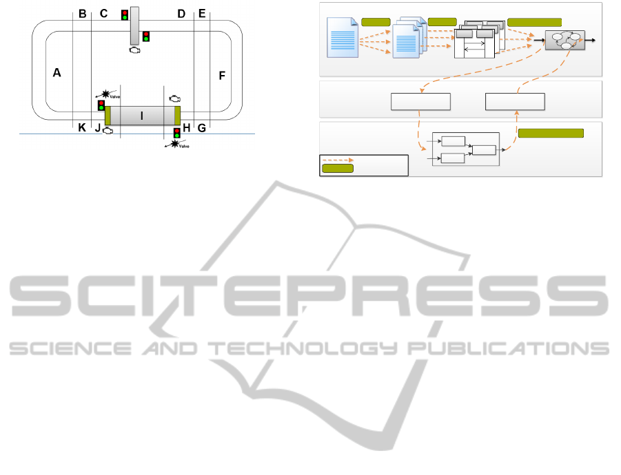
Figure 1: The topology of the canal system. There are
eleven canal segments (A – K), a lock with two lock gates
(bottom of the picture) and a low bridge (top of the picture).
Low bridge and lock are equipped with traffic lights.
such as software intensive embedded systems. We ap-
plied the approach by means of a tool and evaluated it
with a group of students, who concurrently developed
requirements and architecture. The approach proved
beneficial in the detection of inconsistencies between
the requirements and the architecture as well as within
the requirements themselves.
2 APPROACH
2.1 Running Example
We illustrate our approach with the running example
of a canal monitoring and control system (CMCS).
We took the requirements description of this system
from a common case study that was used in the 2011
Workshop on Model-Driven Requirements Engineer-
ing (MoDRE).
The system’s purpose is to control a system of
canals on which ships are cruising. To surmount a dif-
ference in water level a canal may be equipped with
a lock. A lock consists of two lock gates and two
valves that are used to balance the water level. A sec-
ond component in the canal system is a low bridge. If
a ship wants to pass, the bridge needs to be opened.
The CMCS tracks the ships which cruise on the
canals and controls bridges and locks such that ships
can pass. In the original requirements document the
system was meant to handle a flexible canal topology.
However, in order to simplify the development task
we fixed a canal topology with eleven segments, one
lock and one bridge. Furthermore, we included only
two ships into the case study. The topology is de-
picted in Figure 1.
2.2 Artifact Model
Our approach is based on a fixed set of modeling ar-
tifacts and relations between them. The artifacts are
Requirements
Use Case Scenarios
MSCs
Refinement Specification
Architecture
Representation
Function
Interpretation
Function
Formal Specification
Review
Review
MSC Feasibility
Refinement Test
Refinement
Analysis Procedure
Figure 2: Artifacts, relations and analysis procedures with
focus on functional requirements and their mapping onto
the architecture.
used to describe requirements on different levels of
completeness and detail, the system architecture and
a refinement relation between requirements and archi-
tecture. All artifacts and their relations are illustrated
in Figure 2. The purpose of this paper is not to intro-
duce new modeling techniques. In fact, all of the arti-
facts used in our approach may also be represented for
example by SysML or UML diagrams, which would
be completely reasonable. The focus of this paper is
to integrate the different artifacts into a specific pro-
cess and link the artifacts using specific analyses.
2.2.1 Modeling Requirements
To model functional requirements, we employ use
cases, scenarios, message sequence charts, formal
specifications and a data dictionary. Except from the
data dictionary, which is a simple technique for data
modelling, all model elements describe behavior at
increasing levels of formality and completeness.
Use Cases. Use cases informally describe the
functionality and the context of the system from a
user’s perspective. A use case template is provided
including, amongst others actors, a description, trig-
gers, preconditions, success and minimal guarantees
as well as inputs and outputs (cf. (Cockburn, 2001)).
Most of the fields are described in natural language,
while few can contain links to elements from other
modeling artifacts (e.g., inputs and outputs are related
to architecture elements).
Scenarios. Use cases can be supplemented by
scenarios providing informal descriptions about sin-
gle runs of the system under development. A scenario
is defined as a sequence of interaction steps between
the system and its environment. The individual steps
are still described in natural language. Figure 3 gives
an example of such a scenario.
Message Sequence Charts (MSCs). To describe
scenarios more formally message sequence charts
MODELSWARD2014-InternationalConferenceonModel-DrivenEngineeringandSoftwareDevelopment
588
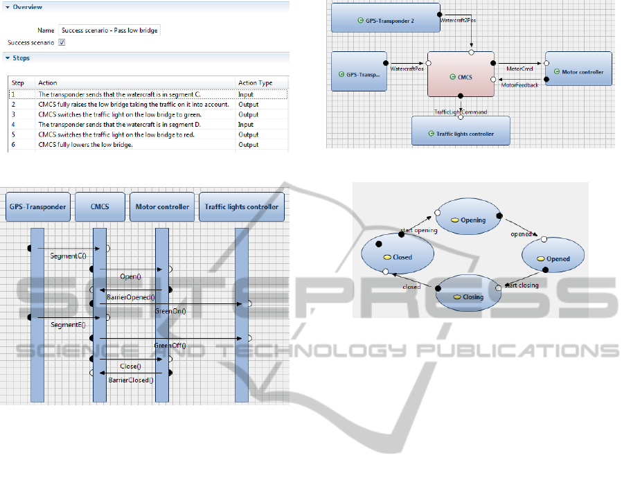
Figure 3: Example of a scenario description.
Figure 4: Example of a message sequence chart (MSC).
(MSCs) (ITU-T, 1999) can be used. In an MSC,
single steps of the corresponding scenario are repre-
sented by the exchange of one or more messages be-
tween the system and its environment. Those mes-
sages, as opposed to sentences in natural language,
already have a formal character. For example, they
contain source and destination ports and their mes-
sages must conform to the corresponding data type of
the port. Figure 4 provides an example of an MSC.
Formal Specifications. Since MSCs only provide
partial descriptions of behavior, we use formal spec-
ifications to progress towards a more completely for-
malized set of requirements. In our approach, a for-
mal specification is a description of an executable in-
put/output behavior which can, for example, be used
in simulation. As modelling technique, we use I/O
automata or code specifications with a Java-like syn-
tax, which is equipped with a formal semantics. For-
mal specifications are intended to combine all mes-
sage sequence charts related to one use case. There-
fore, a formal specification captures the behavior of
the system corresponding a particular use case. It is
important to stress that formal specifications exhibit
total behavior. This means that for every input se-
quence the formal specification determines an output
sequence. On the contrary, message sequence charts
only specify partial behavior in the form of traces con-
Figure 5: Example of a micro architecture specification.
Figure 6: I/O automaton specification of a component.
sisting of exemplary input and output sequences.
Modeling a formal specification for an entire use
case is a challenging task typically leading to rather
complex behavior models. Therefore, we allow the
decomposition of the formal specification into hierar-
chical components that again contain behavior mod-
eled by automata or code specifications. We call such
decompositions micro architectures. The components
exchange messages via named channels. The inter-
face of a component is the set of its input and output
channels. The parallel composition of all components
results in the complete behavior of the formal specifi-
cation. Figure 5 shows such a decomposition in order
to specify a total behavior for the set of messages se-
quence charts of one use case. Figure 6 shows the I/O
automaton behavior specification of component Mo-
tor controller.
Finally, message sequence charts and formal spec-
ifications are related in the following way: The mes-
sages sent in the message sequence charts are inputs
and outputs of the formal specification (e.g., of the
I/O automaton). Compare for example the messages
of MSC entity Motor controller in Figure 4 with the
component Motor controller of the formal specifica-
tion in Figure 5.
Other Requirements. Some requirements, such
as safety requirements, might not be modeled in use
cases. These requirements are typically expressed in
natural language or temporal logic. The respective
formulas can be used to verify the formal specifica-
tion and the architecture as explained in the following
section.
SupportingConcurrentDevelopmentofRequirementsandArchitecture-AModel-basedApproach
589
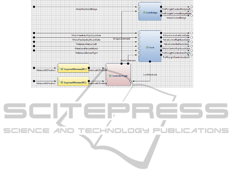
Figure 7: An architecture of a system represented by a network of communicating components.
Data Dictionary. To define simple data types for
use in the formal specifications or the message se-
quence charts a data dictionary is provided. Custom
data types may be constructed from enumerations,
records, arrays and some pre-defined basic data types
such as integers.
2.2.2 Modeling Architecture
The architecture of the system is modeled by the same
means as the micro architecture of formal specifica-
tions, i.e., using a hierarchy of communicating com-
ponents. As mentioned in the introduction we do not
only capture structural properties in the architecture
but also behavior. To enable behavior specification,
components that are leaves in the hierarchy, can be
equipped with behavior descriptions such as I/O au-
tomata. The architecture may also use the data dictio-
nary to specify data types. Figure 7 gives an example
of such an architecture. Note that, although the mod-
eling technique for modeling the micro architecture of
formal specifications and the architecture of the sys-
tem is the same, the actual models and their decom-
position are likely to be very different from each other
(e.g., compare the micro architecture in Figure 5 with
the architecture of Figure 7). This is due to different
concerns of modeling. While the formal specification
aims at formalizing only the functionality of one use
case, the architecture of the system is supposed to im-
plement the functionality of several use cases and ad-
ditionally needs to address non-functional properties
such as extendability or maintainability.
2.2.3 Binding Requirements and Architecture
As both, architecture and formal specifications (and
partly the message sequence charts), describe the in-
terface behavior, they can be related to each other at
the system boundary. However, since the interface
descriptions of the requirements and the architecture
may not match exactly (e.g., due to different levels of
abstraction) they possibly need to be translated. We
use a refinement specification that defines this transla-
tion between the interface behavior of the architecture
and the formal specification of the requirements.
Refinement Specification. A refinement spec-
ification translates between interactions of a for-
mal specification and interactions of an architecture.
Therefore, the input/output channels of the architec-
ture are related to input/output channels of the formal
specification. Typically, beyond simple channel map-
pings, a conversion of data types has to be carried out
to compensate for a different level of abstraction.
Figure 8 illustrates an example of a refinement
specification for a system that switches traffic lights
according to the presence of ships. The formal spec-
ification deals with just one symbolic input stating
whether ships are present or not. Furthermore, the for-
mal specification only has one output, i.e., the color to
display on the traffic light. The architecture, however,
realizes the sensing of the presence of ships by using
two light barriers. Therefore, the architecture has two
inputs: Light Barrier 1 and Light Barrier 2. The ar-
chitecture has one output that switches the traffic light
to green or to red.
To relate the formal specification to the architec-
ture, we map the symbolic input of the specification
to the inputs of the architecture (Representation Func-
tion) and the output of the architecture to the output of
the formal specification (Interpretation Function) as
shown in Figure 8. In model-based testing these func-
tions are also known as abstraction and concretization
functions (Pretschner and Philipps, 2005).
MODELSWARD2014-InternationalConferenceonModel-DrivenEngineeringandSoftwareDevelopment
590
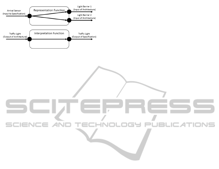
Figure 8: Refinement specification: Mapping requirements
to architecture using representation and interpretation.
2.3 Review and Analysis Procedures
One advantage of a seamless model-based approach
is that it explicitly defines the relationships between
the models. In some cases, the consistency of these
relationships can be assured by precise and expres-
sive analysis techniques. Especially, if the analyses
can be performed (semi)automated, we expect a great
impact on artifact consistency over the development
lifecycle. This supports the incremental and concur-
rent development of requirements and architecture.
In the following, we describe the analysis tech-
niques that are used to assure the consistency of
model relations along the artifact model as described
in the previous section. Figure 2 provides an overview
over the analyses techniques used in our approach.
2.3.1 Manual Review between Use Cases,
Scenarios and MSCs
As described in the artifact model, use cases and sce-
narios are structured but still informal artifacts. That
means, the ability to automatically check a consistent
relation between use cases, their scenarios, and the
transformation of these scenarios into MSCs is lim-
ited. Therefore, we perform manual reviews to check
the consistency of the relation between these three
artifacts. Within the review, we use checklists with
properties that need to be fulfilled including the fol-
lowing:
Between a use case and its scenarios:
• Does every scenario start with the same precondi-
tion and trigger as stated by the use case?
• Does every scenario end with the minimal guar-
antee as stated by the use case?
• Is the list of actors consistent between the use case
and the scenario?
• Are the action types of the scenarios consistent
with the list of inputs and outputs of the use case?
Between a scenario and its MSC:
• Is every step of the scenario translated to at least
one message in the MSC?
• Are all actors of the scenario translated to roles in
the MSC?
• Are the action types consistent to the direction of
messages in the MSC?
2.3.2 Automated MSC Feasibility Checks
between MSCs and Formal Specifications
As described in the artifact model, the formal specifi-
cation of a use case must adhere to all MSCs that are
related to that use case. More precisely, an MSC pro-
vides a sequence of messages that is exchanged be-
tween the system and its environment. The behavior
of the formal specification must reflect this sequence
of messages. We can automatically check this prop-
erty by an MSC Feasibility Check.
This check transforms the sequence of messages
of the MSC into a temporal logic proposition and uses
a model checker to evaluate whether the formal spec-
ification is a model for the logical proposition. If so,
the model checker provides an execution of the formal
specification as evidence.
2.3.3 Automated Refinement Tests between
Formal Specification and Architecture
The formal specification serves as a partial specifica-
tion for the system behavior. In the last section, we
showed how this specification is connected to the ac-
tual architecture of the system by a refinement spec-
ification. To ensure that the system behavior actu-
ally refines the specification we use a Refinement Test
(cf. (Mou and Ratiu, 2012)). In a Refinement Test,
test cases are automatically generated with respect to
the formal specification. Each test case provides a
valid input/output relation given by the formal speci-
fication. The test cases are then automatically trans-
lated to test cases for the architecture by means of the
refinement specification as described in the last sec-
tion. The test cases are executed on the architecture
and the output results are afterwards translated back
to the specification level and compared to the output
results of the original test case. If the results of the test
case execution deviates from the formal specification,
we have found an error.
3 EVALUATION
We applied the approach during two consecutive
master-level practical courses on model-based engi-
neering for students at our university. The task was to
develop the control software for the CMCS.
SupportingConcurrentDevelopmentofRequirementsandArchitecture-AModel-basedApproach
591

3.1 Setting
The overall 15 students that participated in the two
courses were divided into two groups in both courses.
The first group took the role of the requirements en-
gineers, while the second group was responsible for
the system architecture (the architects). The task
of the requirement engineers was to document func-
tional and non-functional requirements and to formal-
ize them as use cases with scenarios, MSCs, formal
specifications and temporal logic assertions. They
also performed the MSC feasibility checks. The ar-
chitects developed the system architecture and created
the refinement specifications. Both groups together
performed the refinement tests and in case of test fail-
ures decided on the actions that need to be taken. Both
the requirements and the architecture was continu-
ously reviewed by the course supervisors. The system
was developed incrementally. As two main functions
we identified controlling the bridge and controlling
the lock. The requirements engineers and the archi-
tects worked in parallel. While the requirement group
documented and formalized the requirements, the ar-
chitects came up with a first rough architecture.
3.2 Tool Support
The whole system, the requirements and the archi-
tecture, was developed using the tool AutoFocus3
(AF3)
1
. AF3 is originally a CASE tool for the model-
based development of embedded systems. It supports
the creation of hierarchical, component-based soft-
ware and hardware architectures. Components in the
architecture hierarchy can be equipped with behavior
specifications, for example using state machines, I/O
tables or code specifications.
Recently, AF3 has been extended by a require-
ments module called MIRA (Teufl et al., 2013). With
MIRA requirements engineers can document and for-
malize requirements directly in AF3 and link them
in various ways to the architecture. One form of re-
quirements that is supported by MIRA are use cases
with scenarios. The scenarios can be formalized us-
ing MSCs. Furthermore, formal specifications for re-
quirements can be developed using the same model-
ing techniques as for the architecture.
Furthermore, AF3 supports all types of analyses
mentioned above out of the box, like MSC feasibility
checks, refinement tests or checking temporal logic
assertions. For these analysis, AF3 uses NuSMV as a
model checker and Yices as an SMT solver
1
http://af3.fortiss.org
3.3 Experiences
In this section we report on our experiences applying
the approach outlined above on the case study. Over-
all, the approach worked well and the system was suc-
cessfully developed by the students. Due to the high
amount of cross checks between the different artifacts
of requirements and architecture there is a high confi-
dence in the correctness of the developed system.
3.3.1 Correctness of Requirements
We found that, as MSCs can reference entities of
the data dictionary and of the high-level architecture
(such as ports), they tended to be very concrete. Thus,
the requirement engineers uncovered several miscon-
ceptions regarding the behavior of the environment
very early. For example, among the requirement engi-
neers there was a different understanding what kind of
information a ship sends to the system (current GPS
position or current canal segment), which was then
decided during the creation of the MSCs.
3.3.2 Concurrent Development of Requirements
and Architecture
Due to the precise definition of the artifact relations
and their continuous assessment, concurrent devel-
opment of requirements and architecture was sup-
ported by the proposed approach. Changes and re-
finements within the requirements or the architecture
were immediately checked for conformance with the
related models. Requirements and architectural ele-
ments could be linked right from the beginning. In
the course of the development the requirements and
the architecture were further refined and formalized
allowing for more expressive analyses to ensure the
correct relation between requirements and architec-
ture. All artifacts were continuously updated and con-
sistent with each other. A typical situation, where our
approach proved beneficial in comparison to simple
informal tracing links, occurred, when the architects
had to change the system design due to a change in
the requirements of one use case. In many cases, the
changed system design fulfilled the altered require-
ments, however, also introduced bugs wrt. some other
use case. These bugs were revealed by the analysis
procedures and led in many cases also to the revision
of other requirements, showing that information flows
not only from requirements to architecture but also in
the other direction.
MODELSWARD2014-InternationalConferenceonModel-DrivenEngineeringandSoftwareDevelopment
592

3.3.3 Explicit Design Decisions
Another aspect of the artifact relation links is that they
explicitly express the design decisions taken during
development. Each model carries information that
originates from information of another model. The
relation links between these models document the de-
sign decision made at the transition between models
and make them explicit. For example, the transition
from the formal specification to the architecture is
captured by the refinement specification. Rather ab-
stract signals like “a ship approaches a bridge” are
translated into concrete logical signals like “Bridge-
Sensor sends a signal”. The design decision to ex-
press the event of the requirement as this specific sen-
sor input is explicitly documented in the refinement
specification between the formal specification and the
architecture. This was especially helpful to assess, if
a specific requirements is fulfilled by the chosen ar-
chitecture. The same applies for the transition of an
informal step in a scenario to a formalized sequence
of events in an MSC.
3.3.4 Scalability
Our approach aims at a modular specification that al-
lows to break down the functionality of a system into
smaller parts and to assess them individually. It is still
an open question if analysis procedures and checks
can be performed in a reasonable amount of time.
The previously described system consisted of two use
cases with an overall of 10 scenarios that were re-
fined into MSCs. All requirements of use cases in
the original specification could be modeled according
by our approach. We additionally elicited 17 further
requirements that were first formalized separately by
means of temporal logic expressions and then mapped
to the two formal specifications that resulted from the
two use cases. 3 of the 17 additional requirements
could not be formalized in the a formal specification
because they were too abstract (i.e., an additional clar-
ification step with the stakeholder is necessary). The
more complex specification of the 2 resulting formal
specifications had an overall state space of 10,976
states. However, the ability to model this specifica-
tion by means of a micro architecture made it possi-
ble to model this specification by a set of automatons
with a maximum of seven states. The most time con-
suming automated analyses were the MSC Feasibility
checks that lasted up to 100 seconds for an MSC with
36 steps and the above mentioned specification. We
think that these numbers are promising for the appli-
cation of the approach also to larger systems.
3.4 Problems
A problem was that the formal specifications got
very complex. Therefore, the requirements engi-
neers started to structure them hierarchically which
resulted in the above-mentioned micro architectures.
This seemed to be problematic at first as apparently
the work for structuring the functionality was done
twice, in the formal specification and in the architec-
ture. However, we noticed the rationales behind the
structuring were quite different between requirement
engineers and architects. Where the requirement en-
gineers mainly strove for easy understanding, the ar-
chitects had goals such as high reuse or an efficient
deployment in mind. If parts of the functional micro
architecture can be used for the system architecture is
a question that we want to look at in the future.
4 RELATED WORK
Our approach follows an artifact-oriented view onto
a development process. That means we focus on the
artifacts to be developed, rather than on the process
steps. REMsES (Braun et al., 2010) provides a pro-
cess guide for supporting requirements engineering
processes in the automotive industry. The artifact
model of this approach provides a basic structure for
the definition of necessary artifacts, their assignment
to abstraction layers and content categories, and the
relations between the artifacts. It defines general con-
trol flow dependencies within requirements engineer-
ing processes. A similar approach for the application
domain of business information systems is provided
by (M
´
endez et al., 2010). Our approach follows this
idea and extends it by providing concrete modeling
concepts to be used in the artifacts and analysis tech-
niques to verify the consistency between them. This
allows for a more precise definition of dependencies
between artifacts.
When models are used as artifacts to describe
different views onto a system, the integration of
those models is an important task. In (Nuseibeh
et al., 1994), the authors relate those views to dif-
ferent ViewPoints and state that “It is necessary to
express and check the relationships between the re-
sultant specification fragments”. The artifact types
that are introduced in this paper can be considered
as ViewPoints, and their relations can be consid-
ered as inter-Viewpoint relationships. A more for-
mal and precise way of describing relations between
models can be achieved by the use of macromod-
els. In (Salay et al., 2012), an application of macro-
models for the formalization of model relationships
SupportingConcurrentDevelopmentofRequirementsandArchitecture-AModel-basedApproach
593

is shown. The work shows positive impacts on in-
ter model consistency during evolution of the sys-
tem. Similar to the ViewPoint templates, macromod-
els could be used to further formalize the relationships
between the models of our approach. While we follow
an analytical approach, i.e., models are constructed
separately and their consistency is maintained and
checked by analysis procedures, there also exist sev-
eral constructive approaches, i.e., models are trans-
formed (semi)automatically and thus are correct-by-
construction. (Guti
´
errez et al., 2008) describe an ap-
proach to automatically transform Use Cases into Ac-
tivity Diagrams. In our approach, this technique could
be used to derive an initial micro architecture for the
formal specification of a use case as the micro archi-
tectures often resemble a kind of activity oriented ar-
chitecture. (Sinha et al., 2008) follow the same ideas
as proposed in this paper by stepwise extending the
use case notion to add precision without discouraging
practitioners, who might not be familiar with formal
languages. Their two-phased definition of a use case,
which accepts use case descriptions in their impre-
cise form and then assists in adding precision through
a wizard driven process, might be a valuable exten-
sion of our use case artifact model. Since scenario
and interaction models are only partial descriptions of
the system’s functionality, there also exists work that
aims at the integration of several scenarios into one
specification (e.g., (Liang et al., 2008)). The work
presented in (Kr
¨
uger et al., 1999) could for example
be used to derive a formal specification from the set
of MSCs in our approach.
5 CONCLUSIONS AND FUTURE
WORK
In this paper we introduced a model-based approach
for the stepwise concurrent development of require-
ments and component architecture. We structured the
used modeling concepts of the approach in an arti-
fact model and defined their relations to each other.
We furthermore showed how these relations can be
backed up by analysis procedures that are formal and
automated to a large degree.
Our experiences from a feasibility study show that
our approach allows for detecting inconsistencies in
requirements early because of the early employment
of (semi)formal techniques. Furthermore, the ap-
proach facilitates concurrent development of require-
ments and architecture due to continuous checks that
guarantee consistency between requirements and ar-
chitecture. These checks can be done in early phases
and therefore allow for concurrently developing re-
quirements and architecture from these phases to the
end of development. In addition, the relations be-
tween the proposed artifacts capture design decisions
explicitly. Furthermore, as far as we can see, the ap-
proach scales well for bigger systems because of the
decomposition of requirements and architecture.
While the approach currently focuses on func-
tional requirements in the form of use cases, we think
that it is well suited to also integrate nonfunctional
requirements into the formal specifications. The idea
is that formal specifications integrate the formalized
functional requirements from a use case as well as
other behavioral properties related to the use case,
e.g., safety or reliability properties. This idea is based
on the hypothesis that many nonfunctional proper-
ties manifest themselves in behavioral properties of
the system. An idea on how to formalize availability
properties and reflect them as behavioral properties is
for example given by (Junker and Neubeck, 2012).
REFERENCES
Braun, P., Broy, M., Houdek, F., Kirchmayr, M., M
¨
uller,
M., Penzenstadler, B., Pohl, K., and Weyer, T.
(2010). Guiding requirements engineering for
software-intensive embedded systems in the automo-
tive industry. Computer Science - Research and De-
velopment.
Cockburn, A. (2001). Writing Effective Use Cases.
Addison-Wesley Professional.
Etien, A. and Salinesi, C. (2005). Managing requirements
in a co-evolution context. In RE 2005.
Guti
´
errez, J., Nebut, C., Escalona, M., Mejas, M., and
Ramos, I. (2008). Visualization of use cases through
automatically generated activity diagrams. In MOD-
ELS 2008.
ITU-T (1999). Formal description techniques - message
sequence chart (msc). Technical report, International
Telecommunication Union (Standardization Sector).
Junker, M. and Neubeck, P. (2012). A rigorous approach to
availability modeling. In MISE 2012.
Kr
¨
uger, I., Grosu, R., Scholz, P., and Broy, M. (1999). From
MSCs to statecharts. In Distributed and Parallel Em-
bedded Systems. Springer US.
Liang, H., Diskin, Z., Dingel, J., and Posse, E. (2008). A
general approach for scenario integration. In MOD-
ELS 2008.
M
´
endez, D., Penzenstadler, B., Kuhrmann, M., and Broy,
M. (2010). A meta model for artefact-orientation:
Fundamentals and lessons learned in requirements en-
gineering. In MODELS 2010.
Mou, D. and Ratiu, D. (2012). Binding requirements and
component architecture by using model-based test-
driven development. In Twin Peaks 2012.
Nuseibeh, B. (2001). Weaving together requirements and
architectures. IEEE Computer.
MODELSWARD2014-InternationalConferenceonModel-DrivenEngineeringandSoftwareDevelopment
594

Nuseibeh, B., Kramer, J., and Finkelstein, A. (1994). A
framework for expressing the relationships between
multiple views in requirements specification. Software
Engineering, IEEE Transactions on.
Pretschner, A. and Philipps, J. (2005). Methodological is-
sues in model-based testing. In Model-Based Testing
of Reactive Systems. Springer Berlin Heidelberg.
Salay, R., Wang, S., and Suen, V. (2012). Managing related
models in vehicle control software development. In
MODELS 2012.
Sinha, A., Kaplan, M., Paradkar, A., and Williams, C.
(2008). Requirements modeling and validation using
bi-layer use case descriptions. In MODELS 2008.
Teufl, S., Mou, D., and Ratiu, D. (2013). Mira: A tooling-
framework to experiment with model-based require-
ments engineering. In RE 2013.
van Lamsweerde, A. (2001). Goal-oriented requirements
engineering: a guided tour. In Fifth IEEE Interna-
tional Symposium on Requirements Engineering.
Whalen, M., Gacek, A., Cofer, D., Murugesan, A., Heim-
dahl, M., and Rayadurgam, S. (2013). Your ”what” is
my ”how”: Iteration and hierarchy in system design.
Software, IEEE.
Yu, E., Giorgini, P., Maiden, N., and Mylopoulos, J. (2011).
Social Modeling for Requirements Engineering. The
MIT Press.
SupportingConcurrentDevelopmentofRequirementsandArchitecture-AModel-basedApproach
595
