
A Domain Specific Language for Stepwise Design of Software
Architectures
Fabian Gilson and Vincent Englebert
PReCISE Research Center, Faculty of Computer Science, University of Namur, Namur, Belgium
Keywords:
Software Architecture, Design Method, Design Rationale, Traceability, Model Transformation.
Abstract:
Stakeholders have to face requirements in increasing number and complexity. Their translations to system
functionalities are often diluted into the overall architecture so that it becomes tricky to undertake future
changes. Since information systems are intended to evolve in terms of functionalities and underlying tech-
nologies, the link between requirements and design artifacts is primordial. Agile design methods and docu-
mentation techniques have emerged in the past years in order to deal with the amount of requirements and to
trace the decision process and the rationale sustaining a software model. Also, it is not unusual that numerous
technologies with similar purpose are confronted to each other during the design phase. In the present work,
we propose an integrated framework combining system requirement definitions, a component-based modeling
language and model transformations. Architecturally-significant requirements are explicitly linked to software
architecture elements and iteratively refined or implemented by model transformations. Any transformation
must be documented, even briefly, and the framework retains the transformations tree. This way, the iterative
decision and design processes are completely documented for future reference or modification, i.e, designers
can (i) see the mapping between a system requirement and its implementation in the architecture model, (ii)
explore design alternatives or apply structural modifications without losing previous versions of the model,
and finally (iii), depending on the level of documentation, at least understand partially the reasons why the
model is how it is.
1 INTRODUCTION
Software systems become complex products where
many people and constraints may intervene. They are
intended to offer many functionalities that can evolve
over time. Many possibilities are often available to
fulfill specific needs which increase the amount of de-
sign choices. A requirement can be scattered over an
architecture model so that it becomes difficult to re-
cover architectural knowledge (Tyree and Akerman,
2005). Without appropriate design decisions and
rationale tracing mechanisms, system maintenance,
evolution and redeployment may be costly and time-
consuming (Watkins and Neal, 1994).
As we present in Section 2, iterative design
method in component-based systems is not a new con-
cept. The main goal of such methods is to face re-
quirements and constraints by integrating them step-
by-step (Bosch and Molin, 1999). However, maybe
the trickiest part resides in ordering these require-
ments since the early decisions taken at the architec-
ture or technological levels may impact the overall
design possibilities (Tang et al., 2006). Making an
early decision, like choosing a particular architectural
style, limits the design possibilities for later decisions.
This may cause expensive rework if the decision was
wrong. For example, if designers go for a two-tier ar-
chitecture and, later on, need to replicate the database
in the cloud, major rework at the architecture level
will be necessary. Likewise, changes in the deploy-
ment infrastructure may trigger non-trivial modifica-
tions at the architecture level (Malek et al., 2012).
We propose in Section 4, an agile-based de-
sign framework intertwining structural models, re-
quirement definitions, design rationale documenta-
tion and model transformations. These underlying
languages are presented in Section 3. The aim of
this work is to structure the iterative design process
around step-by-step refinements and model transfor-
mations (Jansen and Bosch, 2005). On the one hand,
architecturally-significant requirements are expressed
regarding some guidelines. On the other hand, in-
formation systems are modeled in terms of types of
constructs, concrete and interconnected instances and
deployment targets. The framework traces the history
of the iterative decision process with corresponding
67
Gilson F. and Englebert V..
A Domain Specific Language for Stepwise Design of Software Architectures.
DOI: 10.5220/0004709700670078
In Proceedings of the 2nd International Conference on Model-Driven Engineering and Software Development (MODELSWARD-2014), pages 67-78
ISBN: 978-989-758-007-9
Copyright
c
2014 SCITEPRESS (Science and Technology Publications, Lda.)

models. At any time, it is possible to go back to an
earlier model, make a modification and re-apply the
previously defined transformations with minor neces-
sary rework at the architecture level. Decisions and
rationale are first-class entities in the design process
so that we explicitly keep the link between require-
ments and implementing constructs with the reasons
sustaining such decisions. We do not address order-
ing or assessment between requirements, like the Ar-
chitecture Tradeoff Analysis Method (ATAM) (Kaz-
man et al., 2000) or the reasoning method proposed
by Tekinerdogan et al. (Tekinerdogan et al., 2011),
even if such methods can be integrated in our frame-
work.
We challenged our approach on a comparative
case study on a fictitious online book store system.
In Section 5, we present the broad outlines of the case
study and analyze some of its outcomes. We discuss
how our transformation-oriented method helped de-
signers to structure the architectural knowledge, trace
design alternatives and build a documented system ar-
chitecture. We will afterwards discuss the benefits
and limitations of our approach in Section 6. We fi-
nally conclude this paper with our research perspec-
tives and future work in Section 7.
2 RELATED WORK
An increasing amount of research focuses on the rela-
tions between requirements, design decisions, design
rationale and architecture model. The first notable
work proposed by Potts and Bruns (Potts and Bruns,
1988) records the design rationale as single entities
which limits automatic extraction and reasoning be-
tween rationale types. A basis for rationale and de-
cisions reasoning has been proposed by Kruchten et
al. (Kruchten et al., 2006) and a formal language for
decisions modeling was developed by Zimmermann
et al. where they refined the notion of decision into is-
sues, alternatives and outcomes (Zimmermann et al.,
2009).
Although, there is a need for embedded facilities
to maintain a concrete link between decisions and ra-
tionale, and resulting architecture models (de Boer
and van Vliet, 2009). Architecture Rationale and El-
ement Linkage is a more complete technique that in-
tegrates model elements and the rationale sustaining
the associated design decisions (Tang et al., 2007).
Jansen et al. introduce a documentation enrichment
method, supported by a tool suite, to add formal
knowledge even to existing documentation (Jansen
et al., 2009). Zhang et al. propose a formal rep-
resentation model for design rationale with the pos-
sibility to add a link between requirements an pro-
duced artifacts, but these products must be defined in
an existing feature model (Zhang et al., 2013). How-
ever, all these approaches require modelers to main-
tain extra models, often with lots of mandatory de-
tails, so that the workload is significantly increased
with a possible discouraging effect. Also, the ade-
quacy between models is rarely ensured on the long
run. In our method, decisions and rationale are kept
inside requirement models, concretely linked to archi-
tecture model elements in a very simple way.
With model-driven approaches, new design
methods were developed, as Rational Unified
Process
R
(Kruchten, 2004) or the Attribute-Driven
Design (Wojcik et al., 2006). Hofmeister et al. pro-
posed a general model based, among others, on these
two methods (Hofmeister et al., 2007). In their work,
authors stated the need for an iterative design method
that involves decisions and rationale as first class en-
tities. Our method was largely inspired by these rec-
ommendations.
A couple of transformation-centric methods have
emerged. In many of these approaches, models are
either transformed to integrate new requirements or
non functional qualities, or represent systems from
a coarse-grained picture to a fine-grained one (from
model to code, for example). Matinlassi proposed
a technique for quality-driven model transformations
where the author focuses on automation, but only on
quality properties (Matinlassi, 2006). Perovich et al
use a more complex representation for the system
functionalities (Perovich et al., 2009), in terms of,
among others, information flows or policies. But, as
far as we know, they currently do not provide tool
support and concentrate on deployment-related deci-
sions and rationale. TransML is a family of model-
ing languages that provides a holistic approach for
the overall design process with model transformations
and verifications (Guerra et al., 2013). Its main ad-
vantage resides into the smart traceability mechanism
for transformations. However, only part of the for-
malisms are currently implemented. In large scale
projects with complex metamodels, the intrinsic com-
plexity for writing transformation rules is not lowered
and the authors give no guidelines to select the most
appropriate formalism between the profusions of their
languages.
3 MODELING LANGUAGES
OVERVIEW
The present method focuses on software architecture
design. It relies on three languages: a component-
MODELSWARD2014-InternationalConferenceonModel-DrivenEngineeringandSoftwareDevelopment
68

based modeling language, a requirement language
with explicit design decisions and rationale traceabil-
ity links, and a transformation language. In the fol-
lowing sections, we introduce the main concepts of
both modeling languages. Afterwards, we introduce
our specific transformation language in more details.
3.1 Architecturally Significant
Requirement Modeling
In a previous work, we defined a simple modeling lan-
guage to record and trace architecturally significant
requirements (ASR) (Gilson and Englebert, 2011a),
i.e, requirements that have a significant meaning in
terms of architectural artifacts (Clements and Bass,
2010). We provide in Listing 1 a sample requirement
1 // model header (package name)
2 package e xa m pl e ;
3 // asr model name linked to an architectural
model
4 asrmodel cl ie n ts er v er with e x am p le .
cl ie n ts er v er {
5 //assignation of a requirement to a
component
6 func S a yH e ll o assigned S erv er {
7 long description " T h e Ser v er s hal l pri n t ’
He l l o Wo r ld ! ’ t o t h e co n so l e . " ;
8 //design decision type: a transformation set
9 realisation e x am p le . my fi rs t t r a n sf or m a t i o n ;
10 // rationale for this design decision
11 rationale{
12 assessment" Fu nc t io na l it y is t r ivial , a
un i que se r vic e s h oul d mak e t h e t ric k .
" ;
13 strength" V ery s imp l e i mp l em en t at io n wi t h
un i que se r vic e w i th o ut p ar a me te r s . " ;
14 weakness" T h e pr i nt e d m e ss a ge is fi x ed . " ;
15 }
16 }
17 // non functional requirement
18 nonfunc F as t An s we r assigned S er v er {
19 long description " W h en r ece iv i ng a c lie n t
requ e s t , S e rve r sh a l l a n swe r i n l e ss
tha n 1 s eco n d . " ;
20 // fulfill ASR by implem. "Hello" interface
21 implements H e llo ;
22 rationale{
23 assessment" W ith p a rame t er - less s e rvice ,
se r ver re s po n se t i me s h oul d be f a st . "
;
24 assumption" Bec aus e s e rvi ce is t rivial , a
un i que ser v er s hou l d be su ff i ci e nt . " ;
25 constraint" Sho u ld be les s than 1 0 0
si mu l ta ne o us re q ue s ts p e r se c ond " ;
26 }
27 }
28 }
Listing 1: Sample ASR model for a Client-Server.
model of a Client-Server system. Two requirements
are listed: a functional requirement identified by the
name SayHello, and a non functional one named Fas-
tAnswer. They are both assigned to the same model
object Server. We use fully qualified names with sin-
gle dots as delimiters to unambiguously identify mod-
els and constructs.
The present ASR model clientserver is part of
a package and refers to an architecture model named
example.clientserver. Both requirements are de-
scribed following the writing guidelines from Alexan-
der and Stevens (Alexander and Stevens, 2002) and
conforms to the EARS templates (Mavin and Wilkin-
son, 2010). In short, these templates define a struc-
tured way of writing system requirements in natural
language. Specific pieces of information, like events,
or options, are highlighted by specific terms, respec-
tively when and where, and are present in the descrip-
tion at specific places. Amongst the advantages of
this approach, we particularly note its ease of learn-
ing since no new (modeling) language or concept is
necessary to learn, as well as its ability to induce more
completeness and conciseness in requirement descrip-
tions.
Regarding a requirement, a number of decisions
can be taken. We group them in the following cate-
gories:
Assignation: the requirement is assigned to a mod-
eling construct.
Refinement: a lower-level requirement is a refine-
ment of a higher-level one, i.e., concerns part of
the scope of the higher-level requirement, but de-
scribes it more precisely.
Alternative: a lower-level requirement is a possible
refinement alternative for a higher-level require-
ment.
Selection: an alternative is actually selected by the
designers as the implementation solution.
Interface Usage or Implementation: in order to
fulfill a requirement, an existing interface is used
or implemented, or in case of non functional
requirements, the given interface conforms to the
needed properties to achieve this requirement.
Re-assignment: the requirement is reassigned to an-
other modeling construct, i.e, the responsibility
to accomplish the requirement is transferred to
another model element (mainly software compo-
nents).
Realisation: a structural modification must be made
into the component model and this will be ex-
pressed as a model transformation (cfr. Section 4).
ADomainSpecificLanguageforStepwiseDesignofSoftwareArchitectures
69

When a modeler takes a decision, like writing a
model transformation to implement it in the archi-
tecture model, the decision type is recorded in the
model. For any type of decision, a set of rationale
can be added of which the assessment is mandatory.
We briefly present here the type of rationale that can
be filled in an ASR model.
Assessment: the actual reason sustaining the design
decision; this is the only mandatory piece of in-
formation.
Assumption: any assumption made on the environ-
ment or on other model elements.
Strength: any advantage of this decision.
Weakness: any disadvantage or limitation of the de-
cision.
Constraint: any constraint under which the decision
is taken, or a further consequence related to this
decision.
The proposed syntax for ASR models enforces de-
signers to document their choices in terms of assign-
ments of requirement to modeling constructs, and
in terms of refinements of requirements. First, we
explicitly trace the link between a requirement and
the model element in charge of its implementation.
This enhances the architectural knowledge regarding
who is implementing what. Second, we keep the
history of the decisions regarding a requirement (re-
assignments, refinements and alternatives) for docu-
mentation purposes. Third, design decisions must be
documented by at least one reason sustaining such a
choice. A minimum amount of information is manda-
tory in order to avoid putting to much unnecessary or
unwanted effort in documentation tasks. Further de-
tails, like strengths and weaknesses, can be added by
the modeler at his own discretion to justify his choices
more explicitly.
3.2 Architecture Modeling
Attached to a requirement model, a structural defini-
tion of the system must be provided. For this purpose,
we defined a 3-level component-based modeling lan-
guage (Gilson and Englebert, 2011b). We present in
the following how information systems are modeled
in three inter-related stages: definition, assemblage
and deployment (DAD). Wider definitions and justi-
fications of the language constructs are presented in
the aforementioned paper.
3.2.1 Stage One: Definition
Roughly, in the first stage, abstract component types
are connected by link types through interfaces. The
model can be at any level of details and component
types can contain other types connected by inner in-
terfaces. For instance, a first architectural represen-
tation could be composed by only one component
named System with all requirements assigned to it.
Listing 2 illustrates part of the definition stage for our
Client-Server.
1 package e xa m pl e ;
2 dadmodel cl ie n ts er v er {
3 definition {
4 interface H e llo {
5 sync void h e llo () ;
6 }
7 componenttype C l ien t {
8 uses H e llo as he l l o ;
9 }
10 componenttype S e rve r {
11 implements H e llo as he l l o ;
12 }
13 connectortype O n e2 O ne {
14 mode one2one;
15 }
16 linkagetype from C l ien t . h e l lo to Se r ver . h ell o
with O n e2 O ne ;
17 }
18 }
Listing 2: Definition stage for a Client-Server.
As for an ASR model, a DAD model must be-
long to a package. In this case, we decided to use
the same names for both ASR and DAD models for
convenience. We defined a simple interface Hello
with a unique synchronous service without parame-
ters named hello(). This interface is used by a type
of component Client and implemented by a type of
component Server. When an interface is exposed in
any way by a type of component, it becomes a facet of
this component with a given polarity (usage or imple-
mentation). We also define a type of connector which
is point-to-point, i.e. connecting one type of compo-
nent to only one other type of component at a time.
We finally link the Client to the Server with the
One2One type of connector in a provide-require con-
tract through the facets.
A set of primitive types has been defined, as in-
teger, boolean or string. Architects may obviously
define new primitive types or custom data structures
themselves. In a DAD model, a primitive type, a
structure or an interface are all considered as generic
types and can be used to type a parameter.
At this point, we defined the building blocks we
can instantiate and concretely connect during the as-
semblage stage. The type of linkage defined from now
only constrains how the type of components can be
linked to each other (i) through which interface and,
(ii) how many instances of a type of a component will
MODELSWARD2014-InternationalConferenceonModel-DrivenEngineeringandSoftwareDevelopment
70

be involved in the connection.
3.2.2 Stage Two: Assemblage
Now we specified these types of blocks, we can define
a concrete architecture by instantiating and connect
them with concrete links. In Listing 3, we introduce a
communication protocol and complete the definition
of the type of connector, then we present the assem-
blage stage of the DAD model.
1 definition {
2 //omitting previously defined constructs
3 //communication protocol for concrete binding
4 protocol TCP {
5 layer: transport;
6 reliable: true;
7 ordered: true;
8 secured: false;
9 mode: one2one;
10 }
11 // link support protocol (same layer)
12 connectortype O n e2 O ne {
13 mode one2one;
14 layer: transport;
15 accepts TCP ;
16 }
17 }
18 assemblage {
19 // a set of instances of type Client
20 soi c l ien t [0 1 0 0 ] : C li e nt ports {
21 //exposing the required facet hello over TCP
22 C lie nt . h e llo as he l l o on T C P ;
23 };
24 // a set of instances of type Server
25 soi s e rve r : S e r ve r ports {
26 //exposing the provided facet hello over TCP
27 S er v er . h e llo [2 0 ] as h e llo on TCP ;
28 };
29 // a link of type One2One
30 connector con : O n e2 O ne ;
31 //concrete binding from clients to the server
32 linkage from c l ien t . h e l lo to se r ver . h ell o
with con ;
33 }
Listing 3: Assemblage stage for a Client-Server.
The protocol TCP specifies with basic, but extensi-
ble properties, a communication protocol that will be
used to support the connection between instances of
component types. A protocol is defined, among oth-
ers, by the communication layer enabling to specify
a wide range of connection protocols from low-level
protocols like Bluetooth to high-level ones like Telnet
or Java method call. In our case, we use the TCP pro-
tocol and add it to the list of accepted protocols for
our connector type.
We create a set of instances (SoI) for each com-
ponent type previously defined. SoI are declared with
a minimum and a maximum cardinality that express
the amount of instances of the same type that can be
present in a concrete architecture. In our example, a
maximum of 100 instances of the Client component
type can be created. This SoI has one port typed by
the facet hello on the TCP protocol. The Server is
unique and has 20 ports of the type hello available,
also over TCP. Clients SoIs are linked to the server
according to the linkage type defined at the previous
stage. At this point, we specify a concrete architec-
ture instance with a certain amount of each compo-
nent types, available ports (i.e., interface instances)
and connections on specific protocols.
3.2.3 Stage Three: Deployment
As presented in Section 1, a notable deficiency in cur-
rent design methods is the omission of infrastructure
constraints. We believe that this problem can be par-
tially tackled by integrating the constraints as soon as
they appear in the design phase. We provide basic and
extensible building blocks to define the target infras-
tructure. In Listing 4, we specify these types of blocks
and illustrate the abstract deployment phase.
1 definition {
2 // omitting previously defined constructs
3 // type of physical port
4 gatetype E t he r ne t {
5 supports TCP ;
6 }
7 // type of computation node (machine)
8 nodetype C o mp u te r gates {
9 E th e rn e t eth ;
10 }
11 // type of concrete (physical) link
12 mediumtype E 10 0 Ba s eT {
13 supports TCP ;
14 }
15 }
16 assemblage { /
*
hidden for conciseness
*
/ }
17 deployment {
18 // 101 nodes of type Computer
19 node c o mp u te r [101 ] : C o mp u te r ;
20 // cable plugged into computers ethernet
gates
21 plug E 10 0 Ba s eT into c o mp u te r [0 1 0 0]: : e t h ;
22 // clients deployed on computers from 0 to 99
23 deploy c l ien t on c om p ut e r [0 9 9 ] ;
24 // the server is deployed on the 100th
computer
25 deploy s e rve r on c om p ut e r [1 0 0];
26 // the ports typed by the Hello interfaces
accessible from the ethernet gates
27 open c l ien t . h e l lo on co mpu t er [0 99 ] :: e t h ;
28 open s e rve r . h e l lo on co mpu t er [ 100 ]:: eth ;
29 }
Listing 4: Deployment stage for a Client-Server.
ADomainSpecificLanguageforStepwiseDesignofSoftwareArchitectures
71

Three new types of model elements are created at
the definition stage. First, a type of gate specifies a
network interface or a physical port on a computa-
tion device. Gate types support a possibly non ex-
haustive list of protocols. In our example, we define
an Ethernet gate type supporting our TCP protocol.
Second, we define a type of node that can represent
any type of computation machine. A node type can
be equipped by a number of gates of certain types.
Third, type of communication media, such as network
cables, are defined. A type of medium also support a
list of protocols. These physical infrastructure-related
constructs can be more precisely defined by an ex-
tensible property mechanism currently under devel-
opment and out of the scope of this paper.
When we have specified types of nodes, gates
and media, we can define an abstract deployment by
mapping the set of instances onto these physical con-
structs. For this purpose, we have to create 101 nodes
of type Computer (remember we can have up to 100
Client instances and only one Server instance). We
do not need to specify medium instances. Since we
are only concerned by the properties attached to a
type of medium used in the target infrastructure and
how nodes are accessible from outside, we abstractly
plug communication medium types into the gate from
a node.
We now deploy our set of instances on nodes and
open their ports (typed by interfaces) on gates. The
overall communication binding, from abstract tem-
plates defined at the definition stage, to the physical
connections specified here at the deployment through
concrete links over ports at the assemblage, is reified
using the communication protocol. In this example,
we use a unique protocol (TCP), but more complex
verifications with compatible protocols can be done,
depending on user-defined properties.
Note that, in a DAD model, all stages are optional.
One can isolate whatever he wants in a specific DAD
model and import (using the import keyword in the
model header) any other model element defined else-
where. This mechanism will be further developed in
Section 4.4 when we will talk about pattern injections.
4 STEP-BY-STEP REFINEMENT
WITH MODEL
TRANSFORMATIONS
Much research has emerged to structure the architec-
ture design method in an iterative way. We describe
here how the aforementioned languages are used in
our design framework.
During the creation of the architecture of an infor-
mation system, architects usually start from a coarse-
grained architectural style, choose one architecturally
significant requirement (regardless how they priori-
tize them), refine it to more precise ones if necessary
and implement it in the architecture. At some points
in the design process, architects performs some vali-
dation of the produced model(s). During this iterative
process, it often happens that multiple alternatives are
explored or that wrong decisions have been taken so
that architects have to backtrack to a previous version
of the model. As pointed out in Section 1, this de-
cision process and the rationale sustaining a final ar-
chitecture are frequently lost after a while and further
evolutions and bug fixes become time consuming or
error-prone.
The approach used in our framework is
transformation-centric: any change in an architecture
model must be expressed as a model transformation.
In order to test our proposal, we implemented both
languages presented in Sections 3.1 and 3.2 and the
transformation language described in the following
as Eclipse plugins with the Xtext
1
framework. Xtext
is a toolset to build configurable textual editors for
a DSL as Eclipse plugins on top of the Eclipse
Modeling Framework
2
. We also implemented a
transformation engine working on the abstract syntax
tree of our model in the Xtend
3
language. In short,
Xtend is an extension of Java, fully compatible with
Java, introducing lambda expressions among other
facilities, and compiled into Java code.
From the definition of all known requirements
in an ASR model and a first, even empty, DAD
model, any modification to the architecture must be
expressed using one of the following transformation
rules. A single file can group many transformations,
related to one requirement, that will be applied all in
once. A new model is then created by a transforma-
tion engine and this model can be further refined, i.e.
transformed, to implement other requirements.
We group rules related to a specific requirement in
a DAD-Transformations set (DAD-T). Before going
into the description of the existing rules, we present
in Listing 5 the general template of a DAD-T set.
Similarly to DAD and ASR models, a transforma-
tions set belongs to a package. A transformation is al-
ways related to a requirement, identified in the model
by the keyword concerns defined in the linked ASR
model declared on top of the DAD-T file. A DAD
model can also be referenced when the transforma-
tion is linked to a specific architecture model, i.e.,
1
www.eclipse.org/Xtext
2
http://www.eclipse.org/modeling/emf/
3
http://www.eclipse.org/xtend/
MODELSWARD2014-InternationalConferenceonModel-DrivenEngineeringandSoftwareDevelopment
72

1 package e xa m pl e ;
2 // involved asr model (mandatory)
3 asrmodel e xa m pl e . c l ie nt s er ve r ;
4 // involved dad model (optional)
5 dadmodel e xa m pl e . c l ie nt s er ve r ;
6 // transformations set name refering to an ASR
7 transformationset t em p la t e concerns Sa y He l lo {
8 /
*
there should be some rules in here
*
/
9 assemblage {/
*
some new assemblage
*
/}
10 deployment {/
*
some new deployment rules
*
/}
11 }
Listing 5: Template DAD-T set.
the transformations set is not a definition of a pattern
(more details about patterns in Section 4.4). In this
case, the file contains a set of rules to alter the refer-
enced architecture model and, eventually, define new
assemblage or deployment statements. Hereafter, we
present the available transformation rules.
4.1 Creation of Constructs
At some point in the design process, new compo-
nents, interfaces or communication links should be
specified. A creation rule is defined by the keyword
create followed by the definition of the new con-
struct. In Listing 6, we show how the Hello interface
could have been created with related Client facet and
port in a transformation model.
1 // create interface
2 create interface H ell o {
3 sync void h e llo ( ) ;
4 }
5 // create facet in Client component type
6 create facet {
7 uses H e llo as he l l o ;
8 } in C lie n t ;
9 // create port in client set of instance
10 create port {
11 C lie nt . h e llo as he l l o on T C P ;
12 } in c lie n t ;
Listing 6: Creation of the Hello interface.
Any other construct from the definition stage can
be created in a similar fashion, same as for ports (from
the assemblage stage). The transformation engine
will inject the newly created constructs into the bound
DAD model. Prior to a creation, the engine verifies
that no name conflict occurs: names must be unique
by construct type. A check is performed using fully
qualified names to ensure name uniqueness for a spe-
cific type of construct.
4.2 Deletion of Constructs
It is indeed possible to delete constructs from an ar-
chitecture model. Not only any element defined at the
definition stage can be deleted, but also any other con-
struction at the other levels, such as sets of instances,
gates, linkages or deployment statements.
The transformation engine ensures that deletions
are always done in cascade, i.e., all related constructs
or instances are deleted when a particular element
is deleted
4
. For example, Listing 7 is the resulting
model after the deletion of the Client component
type from the model illustrated in Listing 4.
1 definition {
2 interface H e llo {
3 sync void h e llo () ;
4 }
5 /
*
component type Client deleted
*
/
6 componenttype S e rve r {
7 implements H e llo as he l l o ;
8 }
9 /
*
omitting remaining of def. stage
*
/
10 }
11 assemblage {
12 // set of instance typed by Client deleted
13 soi s e rve r : S e r ve r ports {
14 S erv er . h e llo as he l l o on T C P ;
15 };
16 connector con : O n e2 O ne ;
17 /
*
linkage with the soi "client" is deleted
*
/
18 }
19 deployment {
20 node c o mp u te r [101 ] : C o mp u te r ;
21 plug RJ 4 5 into c o mp u te r [0 1 0 0] : : e t h ;
22 /
*
deployment of the soi "client" is deleted
*
/
23 deploy s e rve r on c om p ut e r [1 0 0];
24 /
*
gate opening deleted too
*
/
25 open s e rve r . h e l lo on co mpu t er [ 100 ]:: eth ;
26 }
Listing 7: Deletion of Client component type.
In this example, the related linkage type involv-
ing the Client component type has been removed.
The transformation engine deleted the set of instances
typed by the Client, the linkage where this set of in-
stances appeared, as well as the related deployment
statements. A similar behavior is always applied for
all other model elements where the engine removes all
constructs with a reference to the suppressed element.
4
For a complete view of the relations between model
constructs, please refer to (Gilson and Englebert, 2011b).
ADomainSpecificLanguageforStepwiseDesignofSoftwareArchitectures
73

4.3 Fine-grained Alteration of
Constructs
Frequently, architects need more fine-grained trans-
formations where they can, for example, add a ser-
vice to an interface, add a gate to a node or alter a
data structure. For example, in Listing 8, we modify
the hello interface.
1 alter interface H ell o {
2 // add new asynchronous service with a delay
3 // before saying HelloWorld
4 add async i nv o ke H e l lo ( i n t del a y ) ;
5 // add an input parameter to specify the
message
6 rewrite h e llo {
7 add in string m e ss a ge ;
8 }
9 }
Listing 8: Fine grained alteration of an interface.
A new asynchronous service is added into the in-
terface with a parameter that specifies the delay be-
fore invoking the hello service. The second alter-
ation adds a new parameter to the service to define
the content of the message. Note that for synchronous
services, we have to specify the access type of a pa-
rameter (input, output or both).
For every construct with internal definitions, like
types of nodes or data structures, similar transfor-
mations can be defined. Here again, name validity
checks are performed to avoid conflicts.
4.4 Pattern Definition, Injection
and Replacement
In order to enhance re-usability, design patterns can
be created in our approach. They are expressed as
transformations sets, as illustrated in Listing 9, and
linked to an ASR model specifying their assets (not
presented here, because of lack of space).
The transformations set creates the two necessary
type of components (Observer and Subject) as well
as the interfaces, facets and types of linkage. A pat-
tern must be self-contained, i.e. all needed constructs
are defined in the model, or it can import some exter-
nal resources with the import keyword, similarly to
DAD models.
To inject this pattern into an architecture model,
assume we had a requirement asking for such a pat-
tern, we simply need to include the pattern-related
transformations set, then to replace and merge the tar-
get constructs, as shown in Listing 10. The include
mechanism can be used for any type of reusable trans-
formation. Note that if the merge option is not
1 package e xa m pl e ;
2 asrmodel e xa m pl e . o b se r ve r ;
3 transformationset o bs e rv e r concerns Ob s er v er {
4 create interface I Ob s er v er {
5 async n o tif y () ;
6 }
7 create interface I S ub j ec t {
8 async r e gi s te r ( I Ob s er v er o ) ;
9 async u nr e gi s te r ( I Ob s er v er o ) ;
10 }
11 create componenttype O b se r ve r {
12 implements I Ob s er v er as i o bs e rv e r ;
13 uses I S ub j ec t as i su b je c t ;
14 }
15 create componenttype S u bj e ct {
16 implements I S ub j ec t as i su b je c t ;
17 uses I Ob s er v er as i o bs e rv e r ;
18 }
19 create connectortype S i mpl e {mode one2one;}
20 create connectortype M u lti {mode one2many;}
21 create linkagetype from S u bj e ct . i ob s er v er to
Ob s er v er . io bse rv e r with M ulti ;
22 create linkagetype from O b se r ve r . i sub j ec t to
Su b je c t . i s ub j ec t with S imp l e ;
23 }
Listing 9: Definition of the Observer pattern.
1 package e xa m pl e ;
2 asrmodel e xa m pl e . c l ie nt s er ve r ;
3 dadmodel e xa m pl e . c l ie nt s er ve r ;
4 transformationset in j_ o bs er v er concerns
Ob s er v er {
5 // execute pattern transformation
6 include e x am p le . o bs e rv e r ;
7 // merge definition of Subject into Server
8 replace S u bj e ct by Se r ve r merge;
9 }
Listing 10: Pattern injection with merge.
passed, a construct is totally replaced by another one
without merging their definitions.
The result is presented in Listing 11. An
Observer construct has been created and the Server
now implements and uses the Subject-related inter-
faces. More complex replacements with specific over-
rides can also be defined. For example, one can over-
ride a given facet by another with a compatible defi-
nition (i.e., services signatures and properties).
Other types of transformations exist, but are
not shown here because of lack of space such as
renaming, moving elements, etc. For example, an
inner component type can be moved to another one
or raised up to the root of the model.
MODELSWARD2014-InternationalConferenceonModel-DrivenEngineeringandSoftwareDevelopment
74
1 definition {
2 interface I Ob s er v er {/
*
omitting definition
*
/}
3 interface I S ub j ec t {/
*
omitting definition
*
/
}
4 componenttype S e rve r {
5 implements H e llo as he l l o ;
6 implements I S ub j ec t as i su b je c t ;
7 uses I Ob s er v er as i o bs e rv e r ;
8 }
9 componenttype O b se r ve r {
10 implements I Ob s er v er as i o bs e rv e r ;
11 uses I S ub j ec t as i su b je c t ;
12 }
13 connectortype M u lti {/
*
omitting definition
*
/}
14 connectortype S i mpl e {/
*
omitting definition
*
/}
15 linkagetype from S e rve r . i o bs er v er to O b se r ve r
. i o bs e rv e r with Mul t i ;
16 linkagetype from O b se r ve r . i sub j ec t to S er v er .
is u bj e ct with S i mpl e ;
17 // omitting remaining of file
18 }
Listing 11: After pattern injection.
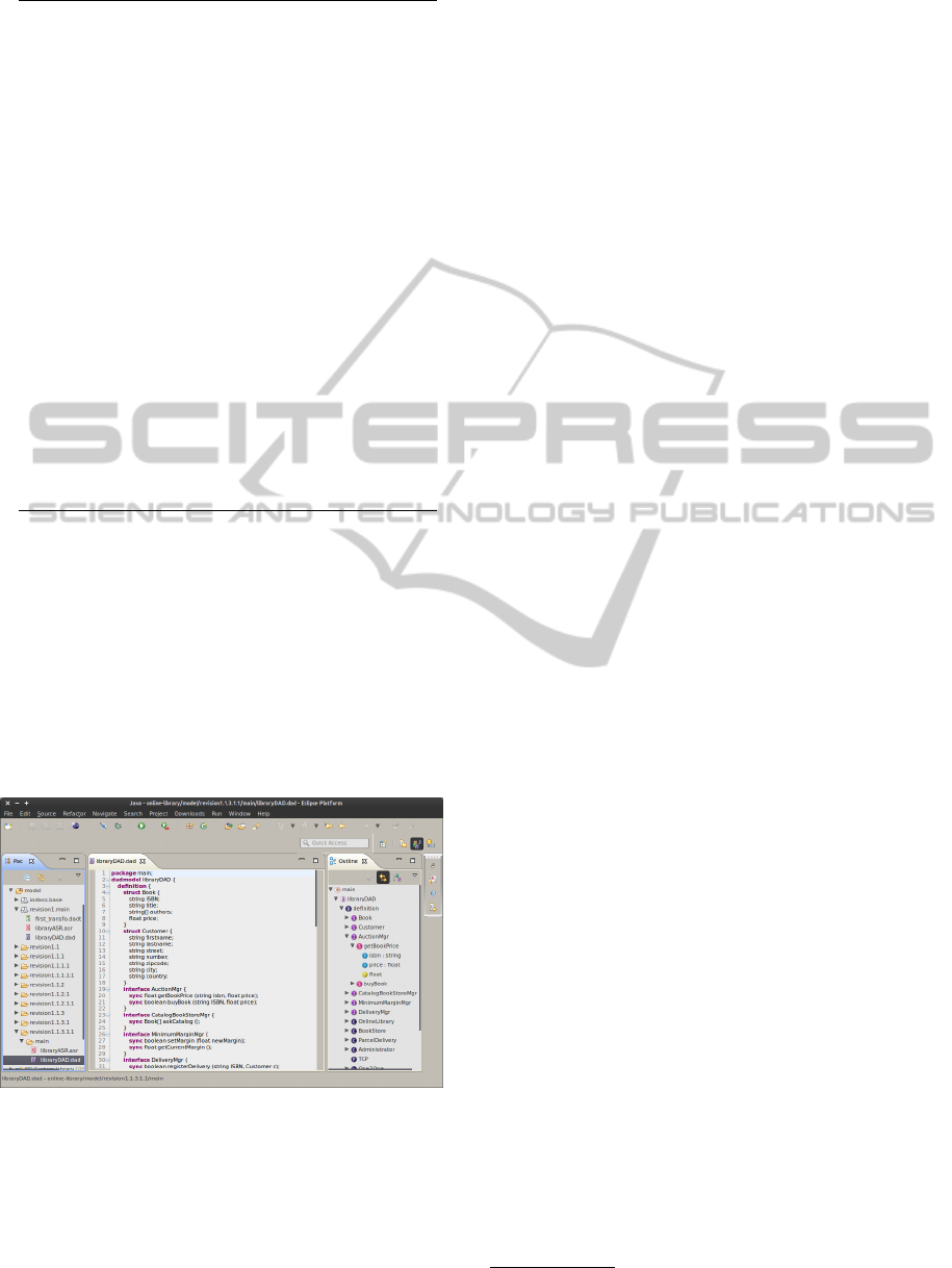
4.5 Decision and History Tracking
Coupled with the rationale and design decision trac-
ing in ASR files, as presented in Section 3.1, we im-
plemented a simple tree-based history tracing mecha-
nism. Figure 1 shows a screen capture of our Eclipse
plugin and illustrates a history tree in the package ex-
plorer (left-hand side of the picture).
Figure 1: Capture of the Eclipse plugin with history track-
ing in package explorer.
Every time a model is transformed, a new model
is created in a separate folder. By convention, we
start from a folder named revision1 and append .1
after a transformation is carried on a DAD model.
When backtracking to a previous model, a new branch
will be created by increasing the higher sub-branch
number. For example, after the model revision
1.1.1.1, we started back from the model at revision
1.1 so a new branch numbered 1.1.2 was created.
This simple mechanism keeps the history of all
created models and can be used to draw a graphi-
cal tree with models as nodes and transformations as
edges for more convenient history browsing.
We intend to review the iteration process in or-
der to define release points where a set of transforma-
tions are grouped to define coarse-grained evolutions
or patches, which make more readable models by hu-
mans and offers possibilities for software configura-
tion management.
Other avenues worth exploring would be to see
how task-oriented methods, like the MyLyn
5
project,
can be integrated into our framework, as well as col-
laborative model editing and versionning (Rutle et al.,
2009).
5 A COMPARATIVE CASE
STUDY
We experimented our approach with a comparative
case study on a fictitious online book store system.
We confronted our framework against SysML (Object
Management Group, 2010). In brief, a web-based on-
line library presents a catalog of books which is the
aggregation of the catalogs of a set of book stores.
When a customer purchases a book, the library starts
an auction between the book stores to buy the book at
the cheapest price. After, the library contacts a deliv-
ery system to pick up the book at the winning book
store and to deliver it to the customer.
The case study was conducted on a group of 24
master students at the University of Namur, all fa-
miliar with UML diagrams, but not with SysML, nei-
ther with our framework. We organized a preliminary
round to evaluate their system modeling competences.
During a lecture, the students were asked to draw a
class diagram based on a 12-pages requirement doc-
ument. The document contained a precise descrip-
tion of use cases for a simplified vehicle inspection
system. Three researchers, also familiar with soft-
ware modeling, classified the diagrams in four cate-
gories based on their syntactic and semantic correct-
ness. This way, we divided the students in two groups
of comparable competences and made teams of two
students for the remaining of the study, the first group
had to design the online library in SysML, the second
with our framework.
5
www.eclipse.org/mylyn/
ADomainSpecificLanguageforStepwiseDesignofSoftwareArchitectures
75

We presented separately the language artifacts and
the tool support to each group, so that the first group
knew only about SysML and the second only about
our languages. Both groups also received the same
description of the system-to-be and were asked to
build it (design and code) in two phases. For the first
phase, the requirements were clearly stated in the doc-
uments to let them getting familiar with the new lan-
guages. For the second phase, the descriptions were
more fuzzy and were related to the evolution of the
system.
After each phase, we evaluated the quality of the
models and the documentation created by the stu-
dents, as well as the functional correctness of the pro-
duced code. We verified to what extend they docu-
mented the decisions sustaining the produced archi-
tectures. Basically, we checked if all model elements
had at least one justification explaining why they were
created into the model.
After the second phase, students were asked to an-
swer to a questionnaire in classroom to evaluate the
expressiveness, the documentation and evolution fa-
cilities of the languages they used. The students also
formulated reviews and advices in a document where
they could express their feelings regarding the afore-
said criteria. In the questionnaire, we used a non-
graduated ruler going from “fully disagree” (0 value)
to “fully agree” (5 value) and measured the students
answers. We also dissimulated redundant questions
in order to double-check the given answers. On the
24 questionnaires, we discarded four of them for each
group because the gaps between the answers to these
control questions were too large.
We present in Table 1 part of the results regard-
ing expressiveness, evolution and documentation fa-
cilities. The second column (S) shows the aggregated
rating for SysML and the last column for our frame-
work (D).
As shown in the Table 1, our framework offers
a significant improvement regarding constructs ex-
pressiveness (question 1). Regarding documentation
(question 2), the difference is not significant enough
to state that our framework gives better results. Con-
cerning model evolution (question 3), the results of
our framework are slightly inferiors. Two aspects can
explain these last values. First, our framework re-
lies on textual models which are, by nature, less vi-
sual than graphical models. Second, during the ex-
periment, due to a bug, the comments present in the
DAD models were lost after a transformation, which
revealed to be a significant lack at participants eyes
when we analyzed their reviewing document.
In their reviews, most of the students noted the re-
quirement traceability improvements offered by our
Table 1: Sample questions and aggregated ratings.
Questions S D
1. The languages constructs allow to rep-
resent:
a. the functionalities of the system. 3.68 4.33
b. the technological and communication
constraints.
1.95 4.48
c. the non functional requirements 3.10 4.12
2. The written documentation allows to ef-
ficiently comprehend the system within the
framework of a modification of the system.
2.63 2.85
3. During the second phase:
a. a major work was necessary to com-
prehend again the architectural concepts of
the system.
0.97 1.21
b. the modeling languages eased the
structural changes linked to the new func-
tionalities to implement.
3.83 3.25
framework as well as the ease of justifying the de-
sign rationale and decisions compared to their experi-
ence (mainly with UML diagrams and text-based doc-
umentation).
6 DISCUSSION
AND LIMITATIONS
The ASR model covers a notable part of the project
backlog, as defined by Hofmeister et al. (Hofmeister
et al., 2007), which is a key document for system en-
gineering. Design rationale, decisions and structured
requirements are present in the model and related to
the modeling constructs that implement them. This
simple mechanism enhances the architectural knowl-
edge without asking much documentation effort. It
can be easily extended to add meta-information re-
garding the project itself, like requirement ordering
methods, standards and so forth.
In terms of the analyzing template for architec-
ture design methods presented by Hofmeister et al,
the proposed framework addresses the questions re-
lated to the produced artifacts and the tools support.
Regarding producing activities, the framework en-
forces documentation of design iterations and records
changes in the architecture model as explicit model
transformations.
The transformation inclusion mechanism offers
a lightweight way to define and re-use patterns in
a transformations set. Working on the concrete
syntax results in more concise rules and improves
the readability of such transformations comparing to
general-purpose transformation languages. However,
reusability of transformations is limited to concrete
syntax elements and patterns injections require to
MODELSWARD2014-InternationalConferenceonModel-DrivenEngineeringandSoftwareDevelopment
76

write mapping rules between pattern constructs and
the current model elements.
Coupled with the history mechanism, design or
technological alternatives can be explored and docu-
mented. Though, a proper graphical visualization fa-
cility should be provided to efficiently identify deltas
between models and to navigate easily between revi-
sions. This way, our framework can be used for soft-
ware configuration management where patches and
redeployment rules are expressed by model transfor-
mations.
Also, a couple of relations between design deci-
sions should be taken into account, like conflicts be-
tween requirements or other natures of impacts, in or-
der to enhance the decision-making process for de-
signers. Furthermore, we should evaluate how a struc-
tured formalism can be integrated into the require-
ment models to define constraints for validation and
simulation purposes.
At current point of development, models are ex-
pressed in textual syntax. Even if such representation
is very expressive, the analysis and communication of
textual models is often less natural for humans. The
underlying Xtext framework is compatible with EMF-
based graphical tools and allows to synchronize both
representations on the same model.
Last, a larger case study should be conducted in
order to evaluate if the transformation-centric method
coupled to a task-oriented approach scales to indus-
trial cases.
7 CONCLUSIONS AND FUTURE
WORK
We introduced a transformation-centric design frame-
work based on Domain Specific Languages. Archi-
tectural constructs are explicitly related to require-
ment specifications and implemented iteratively in the
architecture with model transformations. Every deci-
sion is recorded in the requirement model with its de-
sign rationale. A tool is provided for textual models,
as well as a transformation engine. We conducted a
comparative case study to partially validate our pro-
posal and evaluate its benefits.
In the future, we intend to add behavioral speci-
fications to component types, interfaces and commu-
nication protocols. As a first step, tag-based proper-
ties and logical constraints facilities will be added to
further specify modeling elements. With behavioral
properties, designers will be able to ensure a transfor-
mation does not break behavioral aspects of an exist-
ing architecture.
A Java code generator is under development. At
present time, Java classes and interfaces are generated
from DAD models with method signatures. Primitive
types can be mapped to existing Java types or gen-
erated as separate classes. We intend to maintain a
bi-directional link between architectural models and
Java code for co-evolution purpose.
A visual representation of the history tree with
model deltas should be integrated in the tool to facil-
itate further references to transformations outcomes,
design alternatives and system evolutions. Ideally, a
final goal would be to synchronize a graphical rep-
resentation on textual architecture models to benefit
from the advantages of both textual and graphical vi-
sualizations.
REFERENCES
Alexander, I. F. and Stevens, R. (2002). Writing Better Re-
quirements. Addison-Wesley.
Bosch, J. and Molin, P. (1999). Software architecture de-
sign: Evaluation and transformation. IEEE Int. Conf.
on the Engineering of Computer-based Systems, pages
4–10.
Clements, P. C. and Bass, L. (2010). Relating business
goals to architecturally significant requirements for
software systems. Technical Report CMU/SEI-2010-
TN-018, Soft. Eng. Institute, Carnegie Mellon Univer-
sity.
de Boer, R. C. and van Vliet, H. (2009). On the similarity
between requirements and architecture. J. Syst. Softw.,
82(3):544 – 550.
Gilson, F. and Englebert, V. (2011a). Rationale, decisions
and alternatives traceability for architecture design. In
Proc. of the 5th European Conf. on Software Architec-
ture, Companion Volume, page 4. ACM.
Gilson, F. and Englebert, V. (2011b). Towards handling
architecture design, variability and evolution with
model transformations. In Proc. of the 5th Work-
shop on Variability Modeling of Software-Intensive
Systems, pages 39–48. ACM.
Guerra, E., Lara, J., Kolovos, D. S., Paige, R. F., and Santos,
O. (2013). Engineering model transformations with
transml. Software & Systems Modeling, 12(3):555–
577.
Hofmeister, C., Kruchten, P., Nord, R. L., Obbink, H.,
Ran, A., and America, P. (2007). A general model
of software architecture design derived from five in-
dustrial approaches. Journal of Systems and Software,
80(1):106 – 126.
Jansen, A., Avgeriou, P., and van der Ven, J. S. (2009). En-
riching software architecture documentation. J. Syst.
Softw., 82:1232–1248.
Jansen, A. and Bosch, J. (2005). Software architecture as
a set of architectural design decisions. In Proc. of
the 5th Working IEEE/IFIP Conf. on Software Archi-
ADomainSpecificLanguageforStepwiseDesignofSoftwareArchitectures
77

tecture, pages 109–120, Washington, DC, USA. IEEE
Computer Society.
Kazman, R., Klein, M., and Clements, P. (2000). ATAM:
method for architecture evaluation. Technical Re-
port CMU/SEI-2000-TR-004, Soft. Eng. Institute,
Carnegie Mellon University.
Kruchten, P. (2004). Rational Unified Process: An Intro-
duction. Addison Wesley Professional, 3rd edition
edition.
Kruchten, P., Lago, P., and Vliet, H. V. (2006). Building
up and reasoning about architectural knowledge. In
Proc. of the 2nd Int. Conf. on the Quality if Software
Architectures, pages 43–58.
Malek, S., Medvidovic, N., and Mikic-Rakic, M. (2012).
An extensible framework for improving a distributed
software system’s deployment architecture. Software
Engineering, IEEE Transactions on, 38(1):73–100.
Matinlassi, M. (2006). Quality-driven software architecture
model transformation: Towards automation. PhD the-
sis, ESPOO: VTT technical Research Centre of Fin-
land. VTT Publications 608.
Mavin, A. and Wilkinson, P. (2010). Big ears (the return
of ”easy approach to requirements engineering”). In
Proc. of the 18th IEEE Int. Requirements Engineering
Conf., pages 277–282.
Object Management Group (2010). OMG Systems Model-
ing Language, version 1.2.
Perovich, D., Bastarr
´
ıca, M. C., and Rojas, C. (2009).
Model-driven approach to software architecture de-
sign. In ICSE Workshop on Sharing and Reusing Ar-
chitectural Knowledge, pages 1–8.
Potts, C. and Bruns, G. (1988). Recording the reasons for
design decisions. In Proc. of the 10th Int. Conf. on
Software Engineering, pages 418 –427.
Rutle, A., Rossini, A., Lamo, Y., and Wolter, U. (2009). A
category-theoretical approach to the formalisation of
version control in mde. In Fundamental Approaches
to Software Engineering, volume 5503 of Lecture
Notes in Computer Science, pages 64–78. Springer
Berlin Heidelberg.
Tang, A., Babar, M. A., Gorton, I., and Han, J. (2006). A
survey of architecture design rationale. J. Syst. Softw.,
79(12):1792 – 1804.
Tang, A., Jin, Y., and Han, J. (2007). A rationale-based ar-
chitecture model for design traceability and reasoning.
J. Syst. Softw., 80(6):918–934.
Tekinerdogan, B.,
¨
Ozturk, K., and Dogru, A. (2011). Mod-
eling and reasoning about design alternatives of soft-
ware as a service architectures. In Proc. of the 9th
Working IEEE/IFIP Conf. on Software Architecture,
pages 312–319.
Tyree, J. and Akerman, A. (2005). Architecture decisions:
Demystifying architecture. IEEE Software, 22:19–27.
Watkins, R. and Neal, M. (1994). Why and How of Re-
quirements Tracing. IEEE Software, 11:104–106.
Wojcik, R., Bachmann, F., Bass, L., Clements, P., Mer-
son, P., Nord, R., and Wood, B. (2006). Attribute-
driven design (ADD), version 2.0. Technical Re-
port CMU/SEI-2006-TR-023, Soft. Eng. Institute,
Carnegie Mellon University.
Zhang, Y., Luo, X., Li, J., and Buis, J. J. (2013). A semantic
representation model for design rationale of products.
Advanced Engineering Informatics, 27(1):13 – 26.
Zimmermann, O., Koehler, J., Leymann, F., Polley, R.,
and Schuster, N. (2009). Managing architectural de-
cision models with dependency relations, integrity
constraints, and production rules. J. Syst. Softw.,
82(8):1249–1267.
MODELSWARD2014-InternationalConferenceonModel-DrivenEngineeringandSoftwareDevelopment
78
