
LA6
Local Aggregation in the Internet of Things
Bruno Grac¸a Coelho
1
and Rui M. Rocha
2
1
Instituto Superior T
´
ecnico, Technical University of Lisbon, Av. Prof. Dr. Cavaco Silva, 2744-016 Porto Salvo, Portugal
2
Instituto de Telecomunicac¸
˜
oes, Instituto Superior T
´
ecnico, Technical University of Lisbon, Av. Prof. Dr. Cavaco Silva,
2744-016 Porto Salvo, Portugal
Keywords:
Local In-Network Data Aggregation, 6LoWPAN, Wireless Sensor Networks, Internet of Things, CTP.
Abstract:
The Internet of Things concept is leaving its toddler age where essentially it is a research issue and becoming
a key player in many current applications where Smart Cities are perhaps its greatest exponent. In such real-
world scenarios, efficient large scale machine-to-machine communication is of utmost importance. However,
the current 6LoWPAN standard, proposed by the IETF, has some efficiency problems which can make its
application to the Internet of Things very difficult to scale up. This work transforms the existent 6LoWPAN
implementation enabling a data-centric solution that will overcome the current viability issues of 6LoWPAN
in these networks through the integration of an in-network data processing aggregation mechanism. The pro-
posed data aggregation mechanism increases dramatically the sustainability and network lifetime of 6LoW-
PAN based sensor networks, contributing directly to the Internet of Things revolution.
1 INTRODUCTION
The IoT will connect objects of the world in both
a sensory and intelligent manner combining tech-
nological developments in item identification (”tag-
ging things”), sensors and Wireless Sensor Net-
works (WSN) (”feeling things”), embedded systems
(”thinking things”), and nanotechnology (”shrink-
ing things”)(Sundmaeker et al., 2010). This will
lead to a new model of human-computer interaction
in which information processing is thoroughly in-
tegrated into everyday objects and activities. This
paradigm can also be described as pervasive comput-
ing(Munir et al., 2007) where ”the things think”. Such
pervasive computing creates the need for convergence
between the actual WSNs(Hui and Culler, 2008) and
Internet. Wireless embedded devices have processor,
memory and energy consumption constraints, which
along with the short communication range and dy-
namic environment makes WSNs difficult to design
and maintain. WSNs are data-centric, i.e., a sensor
node does not need an identity (address) because the
communication is performed according to the infor-
mation conveyed. Traditional networks demand the
use of IP addresses, address-centric, and their opera-
tions are based on a point-to-point architecture versus
the many-to-one paradigm, typical of WSNs.
6LoWPAN(Shelby and Bormann, 2009) can guaran-
tee interoperability between WSNs and Internet, due
to IPv6. Nevertheless, this interoperability can hardly
be absolute, because Internet is based on the tra-
ditional IP protocol that is application-independent,
address-centric, with one-to-one communications,
high data-rates, and with almost no resource con-
straints. On the other hand, WSNs are application-
specific, data and location centric, with typical data
flows one-to-many and many-to-one, supporting low
data-rates, and are resources constrained(Z and Kr-
ishnamachari, 2004). In this context, to be viable,
6LoWPAN can benefit from the improvement of some
of its features, such as data aggregation mechanisms,
which will favour robustness, scalability and energy
sustainability.
Data aggregation is the process of aggregating data
from multiple sensors in order to avoid redundant
transmissions and assure compressed information to
the data repository. Aggregation functions are mech-
anisms that optimize wired or wireless sensor com-
munications according to information gathered by the
sensor nodes. Such mechanisms have been studied
since the beginning of WSNs research and its use
can improve the WSN objectivity, reducing the en-
ergy consumption in order to better satisfy the user’s
application(Krishnamachari et al., 2002).
103
Graça Coelho B. and M. Rocha R..
LA6 - Local Aggregation in the Internet of Things.
DOI: 10.5220/0004710401030110
In Proceedings of the 3rd International Conference on Sensor Networks (SENSORNETS-2014), pages 103-110
ISBN: 978-989-758-001-7
Copyright
c
2014 SCITEPRESS (Science and Technology Publications, Lda.)

Currently there are several solutions within traditional
WSN, such as LEACH, CTP(Gnawali et al., 2009),
PEGASIS(Raghavendra et al., 2001), Directed Diffu-
sion(Estrin, 2000) etc. However for 6LoWPAN there
are no solutions developed, deployed, and properly
tested.
A survey regarding current data aggregation so-
lutions in 6LoWPAN shown that no deployed solu-
tion did exist and, furthermore, a great deal of imple-
mentation strategies favoured a service or application
level approach. However, this approach is potentially
less efficient creating additional obstacles to applica-
tions development. For instance, with this approach
the use of automatic code generation frameworks will
become impossible and the coexistence of different
applications will imply the existence of different data
aggregation instances. Regarding the existent data
aggregation mechanisms, the best well suited solu-
tion to fit into a 6LoWPAN is CTP. Despite of being
address-free, the tree-based network topology and its
auxiliary mechanisms contribute directly to enable the
6LoWPAN communication paradigm. Although hav-
ing some issues identified, CTP has the advantage of
being a well-tested routing protocol with embedded
aggregation.
This work aims to implement a data aggregation
mechanism over 6LoWPANs based on CTP without
affecting 6LoWPANs functionalities and thus, con-
tributing to make 6LoWPAN more adequate to the
WSN reality.
The remaining of the paper is organized as fol-
lows. In section section 1, the proposed 6LoWPAN
In-Network Data Aggregation Mechanism architec-
ture along with its corresponding implementation.
Next, we present, in section 3, the tests made to prove
the added value of LA6 solution. Finally, some con-
clusions are drawn.
2 6LoWPAN IN-NETWORK DATA
AGGREGATION MECHANISM
2.1 LA6 Architecture
Berkeley Low-ower IP stack (BLIP)(Dawson-
haggerty, 2010) implements 6LoWPAN stack over
TinyOS through the instantiation of the architecture
composed by IPDispatch, IPRouting, IPAddress and
IPExtensions components. Its architecture organiza-
tion implements a central component, IPDispatch,
supported by the remaining modules, each one
responsible for different operations, complementing
IPDispatch in its functionalities. The LA6 solution
architecture, to be viable, cannot be defined without
IPDispatch. Therefore LA6 In-Network Data Aggre-
gation must intercept every data message to decide
whether to aggregate or to forward the data message.
To do so, we have created a procedure, in the IPDis-
patch component, responsible for intercepting and
decide whether to perform data aggregation.
Data aggregation mechanism should be based on
a tree-based routing protocol in order to create, and
take advantage of the data aggregation opportunities.
Therefore, in order to meet the solution requirements,
some functionalities of CTP were incorporated in the
data aggregation solution. Analysing CTP it was
concluded that to ensure a tree-based routing proto-
col, the following three components: LinkEstimator,
CtpRoutingEngine, CtpForwardingEngine are neces-
sary.
In Figure 1 is shown how these components are
integrated in the proposed in-network data aggrega-
tion solution. Despite taking advantage of CTP, this
solution is designed to avoid being dependent of CTP
to perform data aggregation. To ensure this, an ad-
ditional component, AggregationEngine was devel-
oped. This component is responsible for perform-
ing data aggregation regardless of the routing proto-
col used in the aggregation process. In other words,
this solution takes advantage of CTP tree-based rout-
ing to create data aggregation opportunities that will
be used by the AggregationEngine to realize data ag-
gregation. For this reason, this design approach is ex-
tremely flexible and adaptive because it ensures data
aggregation independence from the routing protocol
or the routing approaches used, namely Mesh-Under
and Router-over(Chowdhury et al., 2008). Since the
AggregationEngine was developed to perform data
aggregation regardless of the packet routing imple-
mentation, it will handle and manage data aggrega-
tion configurations using the traditional default rout-
ing mechanism implemented in IPRouting.
The interactions with AggregationEngine compo-
nent are only realized from the Intercept interface.
This interface implements the same functionalities
that it had in the old CtpRoutingEngine. Since ev-
ery data message traffic flows through IPDispatch, all
data messages will be intercepted and analysed by
the Intercept and according to the AggregationEngine
configurations is realized, or not data aggregation ac-
cording to message data content and the information
pigged-back in the additional CTP header decides
whether to aggregate or to forward data messages.
Therefore, the additional header inherited from
CTP gives the possibility of analysing each packet.
The encapsulation of BLIP messages by the CTP
header is necessary; because it is based on the ag-
SENSORNETS2014-InternationalConferenceonSensorNetworks
104
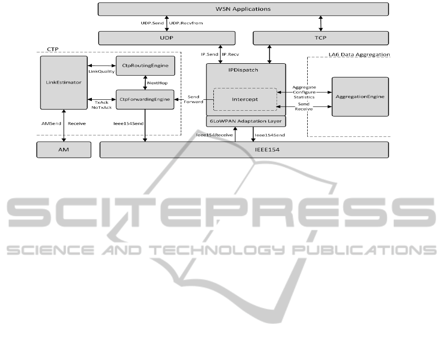
Figure 1: LA6 In-Network Data Aggregation Architecture.
gregation identifier conveyed by this header that the
aggregation process decision is made. Addition-
ally, the AggregationEngine will also be responsi-
ble for performing statistics of the execution process.
The present data aggregation mechanism maintains
the tree-based architecture and performs aggregation
based on the CTP data header conveyed in data mes-
sages.
To integrate the modules comprising this solution,
some significant changes were made in this compo-
nent. Namely, the creation of the interface Intercept
to intercept all aggregated data messages received or
produced locally. For that, an additional CTP header
is added to every aggregation message. As can be
seen in Figure 2, the Intercept interface will evaluate
all received packets interacting with the Aggregatio-
nEngine and with the CtpForwardingEngine accord-
ingly. The Intercept interface will analyse every frame
verifying if it possesses the additional header. If so, it
will redirect the CTP header to CtpForwardingEngine
to preserve and maintain the CTP tree-based routing
and it will redirect the packet content to the Aggre-
gationEngine. The AggregationEngine will perform
data aggregation according to the aggregation iden-
tifier conveyed in the header. All possible cases are
shown in Figure 2. The LA6 data aggregation so-
lution will have six possible cases. If the Aggrega-
tionEngine is performing any kind of data aggrega-
tion, at some point the AggregationEngine will de-
liver the aggregated information to the WSN applica-
tions. That case is visible in Figure 2, and is the first
case enumerated in the figure caption. On the con-
trary, the opposite situation can also happen, when
the WSN application is producing some type of in-
formation that is redirected to IPDispatch for trans-
mission but is intercepted and routed to Aggregatio-
nEngine where is aggregated (highlighted in green). It
can also occur that the information sent by the WSN
applications is not susceptible of being aggregated. In
this case the messages are immediately forwarded by
the CtpForwardingEngine (highlighted in red). The
other case of information being forwarded is the case
where a mote receives an aggregated message, or a
message that is not susceptible of being aggregated in
the present sensor. In this case, the message is im-
mediately forwarded (highlighted in orange). Finally,
when performing data aggregation the Aggregatio-
nEngine sends a message at the end of every aggre-
gation interval. These aggregated messages are pro-
duced at the AggregationEngine and forwarded by the
CtpForwardingEngine (highlighted in light green).
The AggregationEngie component is invoked in
IPDispatch by the Intercept interface. The Aggre-
gationEngine is also a critical component because it
manages the aggregation configuration and according
to it decides whether to aggregate or to forward the
intercepted messages. The data packets susceptible
of being aggregated are different from the others be-
cause they possess an additional CTP Header that en-
capsulates the data packets susceptible of being ag-
gregated. The resulting encapsulation can be seen in
Figure 3. Thus, the CTP header will encapsulate the
message content, the compressed IPv6 header (OSI
layer 3) and the UDP / TCP (OSI layer 4) header. LA6
architecture takes advantage of the code organization
to perform data aggregation based on the information
conveyed at the link layer level header. This approach
will theoretically avoid unnecessary IPv6 decapsula-
tion and data processing.
In fact, the AggreggationEngine intends to be an
independent module that can be used through a prede-
fined interface independently of the circumstances of
its invocation. This characteristic enables its invoca-
tion regardless of the routing approach. This modular
approach allows the use of this component to perform
aggregation even if CTP is not being used because it
LA6-LocalAggregationintheInternetofThings
105
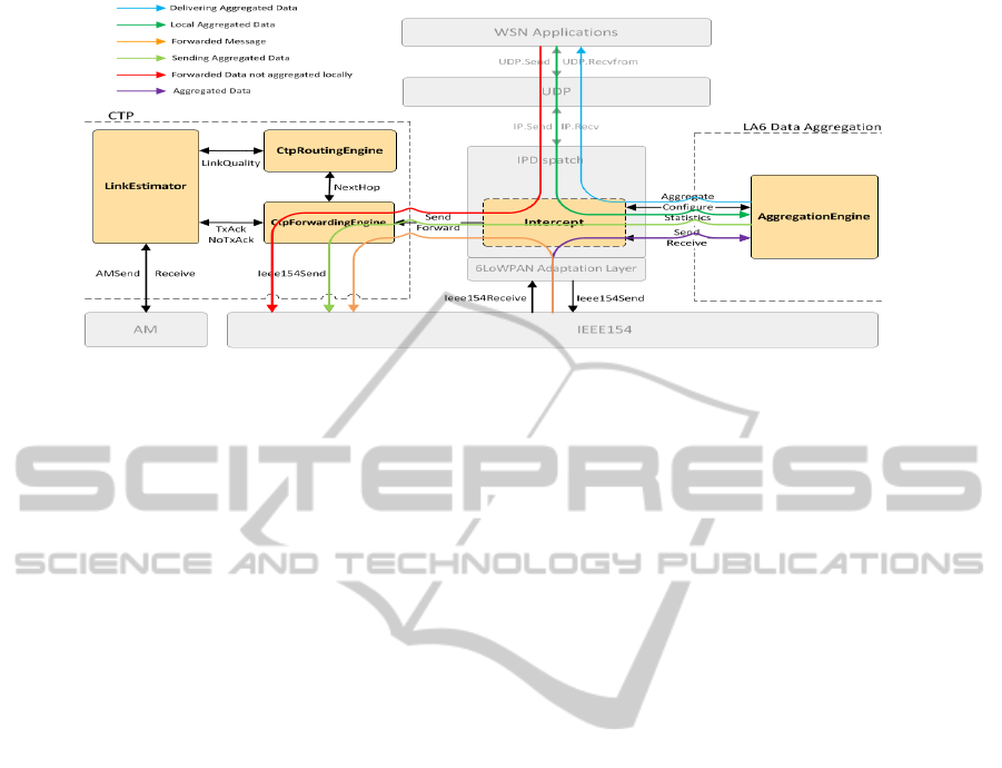
Figure 2: In-Network Data Aggregation invocations process.
only needs an aggregation identifier to perform it.
Due to its independence the AggregationEngine
will also be responsible for managing the aggregation
configuration options, as well as additional statistics
functionality. These functionalities shall be borne by
AggregationEngine because these operations should
be independent of the routing mechanism being used.
2.2 LA6 Implementation
In order to take advantage of the existent BLIP im-
plementation some interfaces were developed linking
BLIP components with the new LA6 modules. Ad-
ditionally, LA6 uses compilation flags to separate the
new functionalities from the existent BLIP features.
This conditional deployment allows the use of LA6
as an add-on solution. Therefore, the implemented
solution favours the deployment flexibility of using,
or not, the LA6 In-Network Data Aggregation mech-
anism.
After ensuring that the CTP key components are
loaded, these must be linked with the existent BLIP
core components, namely IPDispatch. To ensure total
interoperability, the interfaces CtpRoutingEngine and
CtpForwardingExtension were developed along with
the adaptation of the interfaces RootControl, CtpInfo,
CtpCongestion, UnicastNameFreeRouting and Inter-
cept, inherited from CTP. All these interfaces will
only be invoked within CTP flags context assuring
that if these flags are not active, the existent BLIP so-
lution would operate flawlessly.
This implementation approach can, however, in-
troduce some drawbacks or limitations. Firstly, it
needs much more memory. Secondly, to operate prop-
erly, the LA6 solution must use a dual stack. This is
a consequence of using CTP as our tree-based routing
mechanism to perform Data Aggregation.
2.2.1 RoutingEngine
The routing mechanism implemented is based in
CTP tree-based routing (Fonseca et al., 2006). The
developed solution incorporated CtpRoutingEngine
and LinkEstimator in BLIP. This approach separates
the IPv6 traffic from the data aggregated traffic be-
cause the data aggregated traffic is sent according
to a tree-based routing implemented by CtpRoutin-
gEngine while the traditional IPv6 traffic will flow
according to the existent routing implementation of
IPRouting. To link the CtpRoutingEngine with IPDis-
patch, the CtpRoutingEngine interface was devel-
oped. This interface is composed by the procedures:
• CtpRoutingEngine.start()
This procedure was implemented to start the ex-
ecution of the CtpRoutingEngine when the mote
running BLIP system starts.
• CtpRoutingEngine.stop()
On the other hand, the procedure stop() was im-
plemented to do the opposite.
In order to use UnicastNameFreeRouting, CtpInfo
and CtpCongestion interfaces some modifications
were made. Regarding the UnicastNameFreeRout-
ing interface, in LA6 implementation this interface
is responsible for passing the best next-hop (parent)
address from CtpRoutingEngine to CtpForwardin-
gEngine converting AM addresses used in CTP in
short IEEE154 identifiers. Those addresses will be
used by the ForwardingEngine as IEEE154 addresses
for the aggregated messages transmission, enabling a
mesh-under routing approach. CtpInfo and CtpCon-
gestion interfaces are important in the CTP header
manipulation. Since the CTP data packet was mod-
ified to be incorporated in IEEE154 frames, the pro-
SENSORNETS2014-InternationalConferenceonSensorNetworks
106

cedures of this interface were reimplemented in order
to keep its functionality.
2.2.2 ForwardingEngine
Considering that the routing approach used in the
LA6 solution shall implement a forwarding tool for
sending and forwarding messages using link layer
IEEE154 addresses given by the RoutingEngine, the
ForwardingEngine implementation is based on the
CtpForwardingEngine from CTP. However, since the
transmission stack used is the IEEE154(IETF, 2007),
some modifications were made. To incorporate Ctp-
ForwardingEngine in BLIP, the interface CtpFor-
wardingExtension was developed and, according to
the necessity, the following procedures were created:
• CtpForwardingExtension.send()
This procedure is used for sending aggregated
data messages produced locally. The Routin-
gEngine invokes it in the IPDispatch component
to send aggregated data messages according to the
best next hop determined.
• CtpForwardingExtension.forward()
This procedure is used for forwarding aggregated
messages that are not produced locally. These
messages will be forwarded to the best next hop
according to the RoutingEngine. In this case, the
only operations made are the CTP header manip-
ulation and message forwarding.
Figure 3: LA6 data aggregation message format.
The adaptation of AggregationEngine, inherited
from CTP to IEEE154 context, caused CTP data
packet modifications. This new CTP header main-
tains its functionalities, but is smaller. It does not
have the origin AM address of the data packet (can
be avoided because IEEE154 frames already convey
that information), regard Figure 3. Thus, this removal
reduced the overhead in 2 bytes.
2.2.3 Queueing, Congestion Control and
Duplicate Message Detection
The LA6 Forwarding component keeps all CTP func-
tionalities despite the modifications realized. The
CTP queuing system is composed by a per-client
(WSN applications running on each mote) queue, and
by a hybrid send queue. In the LA6 solution, the For-
wardingEngine lost its relation with the WSN applica-
tions. The LA6 Queueing system reimplemented the
client queues using the application port as the identi-
fier of the WSN application. Therefore, this adapta-
tion will unequivocally identify the WSN application
sending each data message.
Additionally, the Queue (FIFO) and Pool struc-
tures used in CTP, IPDispatch and ForwardingEngine
are the same and operate over two different stack im-
plementations: AM and IEEE154. In this implemen-
tation both stacks process messages to transmit in a
round-robin fashion, keeping the fairness of the FIFO
implementation of the up layers. Therefore, despite
of changing the MAC layer below the CtpForwardin-
gEngine, this modification does not affect the fairness
of the new AggregationEngine, maintaining CtpFor-
wardingEngine intact for this subject.
The congestion control functionality was pre-
served, after being adapted to the new CTP data
packet format, see Figure 3. Thus, the Forwardin-
gEngine can detect traffic congestion, viewing the
congested bit, C, or analysing the pull bit, P. With the
previous flags the ForwardingEngine module will be
capable of adapting the transmission timers accord-
ing to the congestion state or link quality information,
piggy-backed in the new aggregated message.
Finally, the issue of duplicate messages transmis-
sion is addressed by LA6 with the use of a cache that
stores the last messages sent, and so, verify if any of
the aggregated messages received is duplicate. If so, it
is dropped. As stated previously, the aggregated mes-
sages convey an additional CTP header that contains
a sequence number and THL. The ForwardingEngine
implementation of LA6 detects duplicate messages
verifying these two values and the IEEE154 source
address carried in the IEEE154 frame.
2.2.4 Aggregation Engine
The AggregationEngine will only be accessible from
the IPDispatch. Its invocation is done at the Intercept
interface. This ensures that all received packets will,
at some point, be analysed in order to verify if it is
eligible of being aggregated or not. This evaluation is
performed using the Aggregation interface called Ag-
gregator. This interface is implemented by Aggrega-
tionEngine and invoked in IPDispatch. It is composed
by the following procedures:
• Aggregator.aggregate()
This procedure is invoked by the IPDispatch Inter-
cept interface and returning the data aggregation
LA6-LocalAggregationintheInternetofThings
107

result. It is this procedure that decides if the in-
tercepted information is aggregated locally or not.
The decision process is realized using a crucial
element the aggregation identifier that identifies
unequivocally the information conveyed and the
operation requested.
• Aggregator.receive()
This procedure is used to deliver the aggregated
information to the WSN applications, or to the
sink node that receives all aggregated data.
• Aggregator.configure()
Aiming to implement control and configuration
functionality for the LA6 In-Network Data Ag-
gregation features the present procedure was de-
veloped.
2.2.5 IPDispatch
Concerning the existent BLIP implementation shall
be stated that the changes realized in BLIP implemen-
tation are minimal. In order to integrate the data ag-
gregation mechanism, the Intercept interface was re-
implemented in IPDispatch. This interface was mi-
grated from CtpForwardingEngine to the IPDispatch
component.
• Intercept.forward()
The IPDispatch component is linked with the
6LoWPAN adaptation layer implementation through
the procedures getNextFrag and unpackHeaders.
These procedures are used for encapsulation and de-
capsulation respectively. Through these procedures
BLIP enables the 6LoWPAN adaptation layer and its
functionalities, such as header compression. With
the LA6 Data Aggregation solution this procedures
will keep its function, but with the additional func-
tionality. They will encapsulate and decapsulate the
ctp data header as well. The implementation of this
functionality does not interfere with the normal IPv6
traffic. Concerning IPDispatch, despite using the ag-
gregation identifier to separate IPv6 traffic from the
aggregated messages, it does not, in any circum-
stance, change the essential interfaces used in BLIP
implementation. These interfaces (IP, UDP) are re-
sponsible for linking layer 3, layer 4 and the appli-
cation level implementations; they represent the OSI
model in BLIP and were preserved intact.
3 TESTS AND EVALUATION
To assess the LA6 In-Network Data Aggregation
Mechanism effectiveness, a test application was de-
veloped to work with a data gathering application that
was developed to operate with the developed solu-
tion in a real environment. The deployed test-bed
was built to reproduce real-life WSN conditions very
closely and, as such, simulates multiple nodes ar-
ranged according to a specific topology. The deploy-
ment infrastructure has an interface to provide infor-
mation regarding the node’s capabilities to the user
through which he has the possibility of configuring
the gathering of environmental conditions measure-
ments. A data sensing application was deployed to
sense and transmit the results over the air in every
minute. This experience was realized in 6LoWPAN
Tagus-SensorNet Test-bed(Pedrosa and Melo, 2009).
In this scenario the 6LoWPAN nodes are organized in
chain, please regard Figure 4. Considering that every
node in the 6LoWPAN performs data aggregation this
network architecture will represent an optimal sce-
nario.
3.1 Overhead Expenditure Analysis
Regarding Figure 5, in terms of overhead traffic the
LA6 In-Network Data Aggregation is worse than the
existent 6LoWPAN implementation.
Figure 5: Overhead number of bytes comparison between
LA6 In-Network Processing Mechanism and traditional
6LoWPAN.
This results from the fact that, LA6 In-Network
Data Aggregation solution needs to maintain the tree-
based routing protocol, and to do so, it will need more
control messages than the traditional 6LoWPAN im-
plementation that does not implement any concrete
routing strategy.
3.2 Energy Consumption Analysis
However, the chain architecture increases the aggre-
gation delay. Due to the aggregation interval defined
of five minutes, the transmission of an aggregated
message will only be realized every five minutes. In
this test case are transmitted only eight data aggre-
gation messages per aggregation interval. In a tradi-
tional 6LoWPAN deployment each node would send
a packet according to the sensing rate.
SENSORNETS2014-InternationalConferenceonSensorNetworks
108
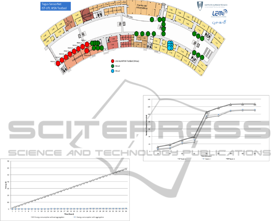
Figure 4: Testbed deployment scenario.
To enable data aggregation along the chain, all
nodes must be synchronized to avoid loosing any ag-
gregated message.
As is visible in Figure 6 the improvement ob-
tained with the developed solution is substantial. This
is an optimal situation for a data aggregation mecha-
nism, because it enables data aggregation in every hop
reducing message transmission dramatically. The en-
Figure 6: Energy consumption comparison between LA6
In-Network Processing Mechanism and traditional 6LoW-
PAN.
ergy consumption cost estimation was realized taking
in consideration the MicaZ nodes used in the 6LoW-
PAN Tagus-SensorNet Test-bed.
3.3 Adaptive Control Traffic
In this test was analysed the behaviour of the WSN
when a new node enters. In this situation all nodes
started transmitting beacons to accommodate the new
node. With this mechanism the developed LA6 in-
network data aggregation took advantage of the func-
tionalities inherited from CTP to adapt its tree-based
routing topology to perform data aggregation. So, re-
garding Figure 7, there is an increase of the messages
transmitted by the neighbours nodes. This is caused
by the auxiliary modules RoutingEngine and LinkEs-
timator. Thus, is possible to conclude that the inte-
gration of CTP functionalities is was achieved with
success.
Figure 7: Number of beacons transmitted when detected a
new node appears.
4 CONCLUSIONS
The traditional WSNs are data-centric networks used
mainly for sensing the environment and transmit col-
lected information cooperatively using a multi-hop
communication paradigm. The WSNs implement a
multi-point to point network, where all nodes sense
the environment and communicate the information
until the sink node that passes the information to a
central repository.
In 6LoWPAN solutions an address-centric point-
to-point network is implemented instead of a more
suitable point-to-multipoint data-centric paradigm,
which has consensual advantages as to what concerns
most of the WSN application scenarios.
Considering the existent state-of-the-art, until now
there was no in-network data processing mechanism
solution designed or implemented for 6LoWPAN ex-
cept those that are integrated right into the applica-
tions itself and therefore not benefiting of a more gen-
eralized and optimized approach.
As a result of the necessity of improving 6LoW-
PAN implementations this paper proposes the LA6
In-Network Data Aggregation Mechanism capable
of creating opportunities to perform data process-
ing within a 6LoWPAN. To do so, adaptations to
the existing 6LoWPAN BLIP implementation (for
tinyOS) were done, which took advantage of CTP
LA6-LocalAggregationintheInternetofThings
109

typical components to support a solution capable of
aggregate data throughout an entire WSN. The LA6
solution not only implements data aggregation, but
also creates the conditions to accommodate other in-
network processing mechanisms. This flexible mod-
ule based implementation was used to implement data
aggregation, aggregation configuration and statistics.
Finally, considering the observed performance of
a WSN testbed running our LA6 solution, one could
confirm the predictable overhead traffic due to the
CTP approach used, when compared with the default
6LoWPAN routing implemented in BLIP. However,
this is a small price to pay when the significant energy
savings obtained using the implemented LA6 data ag-
gregation are taken into account. Indeed, the advan-
tages of using a in-network data aggregation mecha-
nism as the one LA6 can offer, are beneficial for most
of the application running on WSNs.
REFERENCES
Chowdhury, A. H., Ikram, M., Cha, H.-s., Redwan, H.,
Shams, S. M. S., Kim, K.-h., and Yoo, S.-w. (2008).
Route-over vs Mesh-under Routing in 6LoWPAN.
Dawson-haggerty, S. (2010). Design, Implementation, and
Evaluation of an Embedded IPv6 Stack. PhD thesis,
University of California, Berkeley.
Estrin, D. (2000). Directed Diffusion : A Scalable and Ro-
bust Communication Paradigm for Sensor Networks-.
Networks, pages 56–67.
Fonseca, R., Gnawali, O., Jamieson, K., Levis, P., and Woo,
A. (2006). The Collection Tree Protocol ( CTP ). De-
sign.
Gnawali, O., Fonseca, R., Jamieson, K., Moss, D., and
Levis, P. (2009). Collection Tree Protocol. Design,
pages 1–14.
Hui, J. W. and Culler, D. E. (2008). IP is dead, long live IP
for wireless sensor networks. Proceedings of the 6th
ACM conference on Embedded network sensor sys-
tems - SenSys ’08, page 15.
IETF (2007). RFC 4944, Transmission of IPv6 Packets over
IEEE 802.15.4 Networks.
Krishnamachari, B., Estrin, D., and Wicker, S. (2002). The
Impact of Data Aggregation in Wireless Sensor Net-
works. International Workshop on Distributed Event-
Based Systems.
Munir, S. A., Ren, B., Jiao, W., Wang, B., Xie, D., and
Ma, J. (2007). Mobile Wireless Sensor Network : Ar-
chitecture and Enabling Technologies for Ubiquitous
Computing. IEEE Computer Society, (Advanved In-
formation Networking and Applications).
Pedrosa, L. D. and Melo, P. (2009). A Flexible Approach to
WSN Development and Deployment. Networks, x:1–
12.
Raghavendra, C. S., Lindsey, S., and Lindsey, S. (2001).
PEGASIS : Power-Efficient Gathering in Sensor In-
formation Systems Stephanie Lindsey. Systems Re-
search.
Shelby, Z. and Bormann, C. (2009). 6LoWPAN : The Wire-
less Embedded Internet. First edit edition.
Sundmaeker, H., Guillemin, P., Friess, P., and Woelffl
´
ee, S.
(2010). Vision and Challenges for Realising the In-
ternet of Things. Number March. Cluster of European
Research Projects on the Internet of Things, Brussels
- Belgium.
Z, M. and Krishnamachari, B. (2004). Integrating Future
Large-scale Wireless Sensor Networks with the Inter-
net.
SENSORNETS2014-InternationalConferenceonSensorNetworks
110
