
A Formal Semantics for Sequence Diagrams and a Strategy for System
Analysis
Lucas Lima, Juliano Iyoda and Augusto Sampaio
Centro de Inform
´
atica, Universidade Federal de Pernambuco, Recife, Brazil
Keywords:
Sequence Diagrams, SysML, Semantics, CML.
Abstract:
We propose a semantics for Sequence Diagrams based on the COMPASS Modelling Language (CML): a
formal specification language to model systems of systems. A distinguishing feature of our semantics is that
it is defined as part of a larger effort to define the semantics of several diagrams of SysML, a UML profile
for systems engineering. We have defined a fairly comprehensive semantics for Sequence Diagrams, which
comprises sequential and parallel constructors, loops, breaks, alternatives, synchronous and asynchronous
messages. We illustrate our semantics with a scenario of a case study of a system of systems. We also discuss
an analysis strategy which involves an integrated view of several diagrams.
1 INTRODUCTION
During the last decade, a variety of semantics for Se-
quence Diagrams (SD) were proposed (Cavarra and
K
¨
uster-Filipe, 2005; Eichner et al., 2005; Haugen
et al., 2005; Storrle, 2004). This shows their impor-
tance and application in both academia and industry.
Some new operators like parallel composition,
loops and breaks have made the language much more
expressive than the previous versions. The use of
these new constructs makes the interpretation of this
diagram a much more complex task. There are many
possible meanings to Sequence Diagrams. Explicit
semantic variation points described in the OMG stan-
dard (Object Management Group, 2012) and lack of
meaning for specific cases make the task of defining
a unique and definitive formal semantics nearly im-
possible (Micskei and Waeselynck, 2011). A more
reasonable approach is to define a semantics accord-
ing to the purpose the Sequence Diagrams are used
for. An even greater challenge is to define compatible
semantics with other diagrams.
The goal of this work is to define a formal se-
mantics for Sequence Diagrams which is amenable
to automatic verification and which is compatible
with the semantics of other behavioural and struc-
tural SysML Diagrams. SysML (Object Management
Group, 2012) is a UML 2 profile developed for sys-
tems engineering and which has an established indus-
trial support and tool mechanisation. As it is a lan-
guage derived from UML, SysML and UML share
several features. In particular, the SysML Sequence
Diagram differs from its UML counterpart only con-
cerning a few syntactic constructs.
We have defined a fairly comprehensive seman-
tics for Sequence Diagrams, which comprises se-
quential and parallel constructors, loops, breaks, al-
ternatives, synchronous and asynchronous messages.
Our semantics allows us to verify the consistency of
an entire collection of SysML diagrams. Although
our focus here is on the semantics of Sequence Di-
agrams (SD), the semantics of Activity Diagrams
(AD), State Machine Diagrams (STM), Block Defi-
nition Diagrams (BDD) and Internal Block Diagrams
(IBD) are being defined in the context of the COM-
PASS project
1
: a research project on model-based
techniques for developing, analysing and maintaining
systems of systems (Jamshidi and Jamshidi, 2009).
The semantic domain we use is the COMPASS
Modelling Language (CML) (Woodcock et al., 2012):
a formal specification language that integrates a
state based notation similar to VDM++ (Fitzger-
ald and Larsen, 2009), a process algebraic notation
like CSP (Hoare, 1985) and Dijkstra’s language of
guarded commands. It supports the specification and
analysis of state-rich distributed specifications. Ad-
ditionally, CML supports step-wise development by
means of algebraic refinement laws.
Figure 1 displays an overview of our approach.
1
Comprehensive Modelling for Advanced Systems-of-
Systems. http://www.compass-research.eu
317
Lima L., Iyoda J. and Sampaio A..
A Formal Semantics for Sequence Diagrams and a Strategy for System Analysis.
DOI: 10.5220/0004711603170324
In Proceedings of the 2nd International Conference on Model-Driven Engineering and Software Development (MODELSWARD-2014), pages 317-324
ISBN: 978-989-758-007-9
Copyright
c
2014 SCITEPRESS (Science and Technology Publications, Lda.)
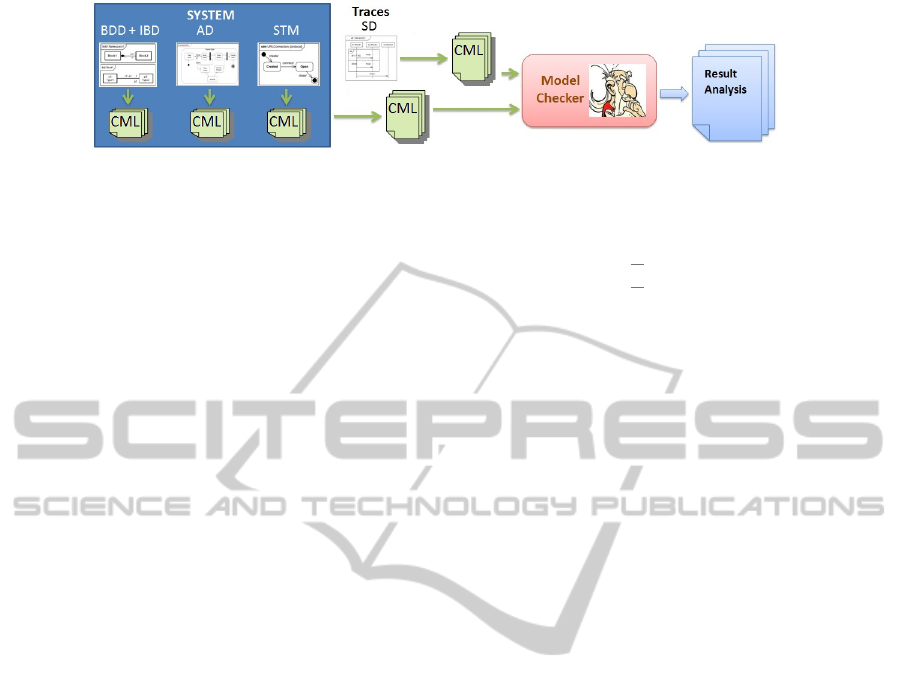
Figure 1: Approach for an integrated model analysis.
All diagrams have a semantics defined in CML.
Sequence Diagrams are used to validate the model of
the system, which comprises all the other diagrams.
The system is modelled as a set of diagrams like
BDDs, IBDs, ADs, STMs and SDs. Each of these
diagrams is translated into a CML specification. A
model checker then takes as input the corresponding
CML models of each diagram and verifies whether
there is any inconsistency with respect to the traces
defined by the Sequence Diagram.
The remainder of the paper is organised as fol-
lows. We introduce CML in Section 2. Section 3 de-
tails our semantics for Sequence Diagrams. An appli-
cation of our semantics to an example is developed in
Section 4. In Section 5 we consider related work. Fi-
nally, our conclusions and future work are presented
in Section 6.
2 CML
This section provides an example to give an intuition
of how CML looks. Figure 2 presents part of a speci-
fication of a Producer-Consumer problem. It declares
two channels put and get that communicate natural
numbers (nat), and four processes. Processes are the
main elements of a CML specification; systems and
their components are both specified by processes that
encapsulate some state and communicate with each
other and the external environment through channels.
A process may declare any number of actions, and
must contain an anonymous main action, which spec-
ifies the behaviour of the process. An action is the
basic behavioural unit in CML. It specifies a flow of
events using communication patterns combined via
CSP-like operators.
Process Buffer has as state a sequence of ele-
ments and it is composed of two actions, ADD and
REM. The former receives an item through the channel
put?x to be added to the buffer, which is performed
by concatenating to the sequence the element just re-
ceived. However, this only happens in case the guard
[len b < 5] is true, assuming that the buffer has at
most 5 elements. The latter action sends through the
get! channel the head of the sequence only if there
channels
put, get: nat
process Producer = ...
process Consumer = ...
process Buffer = begin
state b: seq of nat
actions
ADD = [len b < 5] & put?x -> b := bˆ[x]
REM = [len b > 0] & get!(hd b) -> b := tl b
@ mu X @ (ADD [] REM); X
end
process System = (Buffer [|{|put,get|}|]
(Producer ||| Consumer))\{|put,get|}
Figure 2: CML excerpt.
is some item in the buffer state. The main action
recursively yields a choice ([]) of these two other
actions. We omit processes Producer (which adds
some item to the buffer using the put! channel) and
Consumer (which removes some item of the buffer
using the get? channel) for simplification. Finally,
the System process represents the overall specifica-
tion, which composes the Producer, Consumer and
Buffer processes. As the Producer and Consumer
do not communicate with each other they are inter-
leaved (|||), and their composition is put in parallel
([|{|put,get|}|]) with Buffer synchronising on
the channels put and get. These channels are made
internal using the hiding operator (\).
3 A SEMANTICS FOR
SEQUENCE DIAGRAMS
This section introduces our semantics as a mapping
from SysML Sequence Diagrams to CML. This map-
ping is written in the form of translation rules. The
translation is defined as a recursive function that takes
as input elements of a Sequence Diagram and yields
as output its corresponding semantics in CML. Each
rule has the form LHS → RHS, where the LHS is
a piece of a Sequence Diagram and RHS is the cor-
responding semantics in CML. Although we have a
set of rules covering a large set of elements, due to
MODELSWARD2014-InternationalConferenceonModel-DrivenEngineeringandSoftwareDevelopment
318

space limitations we present only a subset of these
rules. The complete set of rules comprise mes-
sages (synchronous, asynchronous and reply), mes-
sage arguments, local attributes of an interaction,
combined fragments (i.e. the composite constructions
PAR, STRICT, SEQ, ALT, OPT, BREAK, LOOP, and
CRITICAL), guards, state invariant, interaction use
and gates (see (Miyazawa et al., 2013) for the com-
plete set). The CML code contains underlined terms
to indicate that such terms are not CML but are part
of the translation metalanguage. They may represent:
i) elements that are not explicit in the Sequence Dia-
gram (for instance, a unique identifier of a message);
ii) recursive function calls to the translation rule; or
iii) ellipsis omitting elements that repeat. We use rect-
angles enclosing the separator character of a list. For
example,
.
{1,2,3} produces the list 1.2.3.
3.1 Sequence Diagram
Rule 3.1 is the top-level translation of an arbitrary Se-
quence Diagram A into CML. It basically composes
all lifelines A1, A2, . . ., An in parallel and hides con-
trol events. In this work, the semantics of Sequence
Diagrams makes use of the behaviour part (CSP style)
of CML only.
Rule 3.1 Translation rule for a Sequence Diagram.
A1 A2 An
...
sd
A
↓
chanset
Hidden = {|join,break,...,endInteraction|}
process A = A_ID, A1_ID, A2_ID,..., An_ID:ID
@ begin
actions
A1_def = T(A1)
A2_def = T(A2)
...
An_def = T(An)
@ let Lifelines =
{|( A1_def, α(A1 def)),
( A2_def, α(A2 def)), ...,
( An_def, α(An def))|}
within (|| (A, CS) : Lifelines @ [CS] A);
endInteraction.A_ID \ Hidden
end
The declaration chanset Hidden = ... defines
a set of control events (channels) that are hidden in the
translation. These events are introduced by other rules
and are explained below. The declaration process
A = A ID, A1 ID, A2 ID, ..., An ID:ID defines
the signature of the process A, where A1 ID, A2 ID,
..., An ID are the identifiers of the blocks A1, A2, ...,
An, respectively. The actions A1 def, A2 def, . . .,
An def are defined as the translation of each lifeline
to CML. We assume that the translation rule is carried
out by a function called T(). Therefore, T(A1), T(A2),
. . ., T(An) are recursive calls to rules 3.2–3.7.
The main behaviour of the Sequence Diagram is
defined in terms of a let-within construction, which
is similar to let-in expressions of functional pro-
grams. The variable Lifelines stores a set of pairs,
where the first element of the pair is the CML trans-
lation of a lifeline, and the second element of the
pair is the alphabet of the lifeline. The function
α(P) yields the alphabet of P. The expression (||(A,
CS): Lifelines @ [CS] A) combines in parallel
(||) all actions from Lifelines, where (A,CS)
ranges over the elements of Lifeline, and [CS] A
declares all events (channels) used by A. The parallel
composition of the lifelines is followed in sequence
by the event endInteracton.A
ID to signal the end
of the execution of the diagram. This is particularly
useful when we compose the CML of a Sequence Di-
agram with the CML of other diagrams. Finally, we
hide the control channels stored in Hidden.
3.2 Sequential Composition
Rule 3.2 shows how fragments of a lifeline in sequen-
tial composition are translated.
Rule 3.2 Sequential composition.
...
...
X1
X2
Xn
...
→
(T(X1);T(X2);...;T(Xn))
[|break.i|> Skip
Note that there is no explicit constructor for se-
quential composition in a Sequence Diagram as it is
the default operator applied along a lifeline. X1, X2,
. . ., Xn are the sub-diagrams of the lifeline that are
executed in sequence. Note that these sub-diagrams
can be anything like a message being sent or a com-
bined fragment like the parallel composition. The
dashed rounded boxes in Rule 3.2 are not part of the
syntax of Sequence Diagrams. They only help us
in defining the top-level sub-diagrams that are run-
ning in sequence. The semantics of sequential com-
position is defined as a call to the translation func-
AFormalSemanticsforSequenceDiagramsandaStrategyforSystemAnalysis
319
tion T() for each sub-diagram in sequence. The ac-
tion P;Q denotes sequential composition of P and Q
in CML. BREAK is an exception handling facility
similar to the break command in C. The exception
operator [|break.i|> Skip is a syntactic sugar for
a mechanism to interrupt actions in CML according
to a trigger event. It catches any BREAK exception
raised inside X1, X2, . . ., or Xn. The meta-variable i
uniquely identifies which BREAK has been handled.
If a BREAK is raised, the sequential composition is
interrupted and finishes succesfully (Skip). The de-
tails on how BREAK works is described in Rule 3.6.
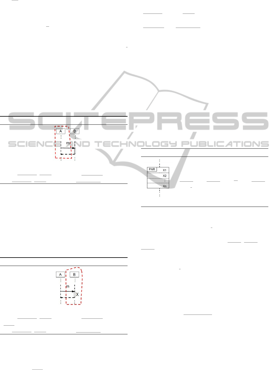
3.3 Messages
Rules 3.3 and 3.4 show the translations of syn-
chronous message calls with a reply message.
Rule 3.3 Sending a synchronous message.
↓
startname(m).id(m).A_ID.B_ID.argsIn(m) ->
endname(m).id(m).A_ID.B_ID.argsOut(m) -> Skip
A synchronous message exchanged between two
blocks is translated into two channels in CML, rep-
resenting the dispatch of a message (start) and the
arrival of its acknowledgement (end). Rule 3.3 shows
how the sender lifeline is translated to CML: it blocks
other activities until it receives an acknowledgement
from the receiver lifeline. The dashed line on the top-
side of Rule 3.3 emphasises the fact that this rule is
about the sender lifeline.
Rule 3.4 Receiving a synchronous message.
↓
startname(m).id(m).A_ID.B_ID.argsIn(m) -> Skip;
T(X);
endname(m).id(m).A_ID.B_ID.argsOut(m) -> Skip
Rule 3.4 translates to CML the receiver lifeline,
which receives a message and may itself perform ad-
ditional tasks X before replying to the sender. That is
why we have T(X) between the two events in Rule 3.4.
Events like start and end carry information
about the message. Every message has a name
(name(m)), an id (id(m)), and knows who is the sender
(A_ID), the receiver (B_ID) and what its arguments are
(argsIn(m) and argsOut(m)).
In Rule 3.3, the fact that the sender of a syn-
chronous message is blocked (until the reply is re-
ceived) is captured in CML by a single action that en-
forces the uninterrupted sequence of these two chan-
nel events. On the other hand, in Rule 3.4 these chan-
nel events are captured by another CML action that
can have other events between them.
The next rules detail the behaviour of parallel
composition, break, and loop. These combined frag-
ments are also composite constructors like sequential
composition, and are also recursively defined.
3.4 Parallel Composition
Rule 3.5 shows the translation to CML of a parallel
composition.
Rule 3.5 PAR combined fragment.
→
(T(X1) ||| T(X2) ||| ... ||| T(Xn));
join.i -> Skip
We assume that each PAR of the Sequence Dia-
gram has a unique identifier i. Let X1, X2, . . ., Xn be
operands running in parallel. Then, the parallel com-
position is the action that composes T(X1)
, T(X2), . . .,
T(Xn) in interleaving (|||). The parallel composition
ends when every operand ends in all lifelines com-
posed in parallel. This synchronised end happens at
the event join.i.
3.5 Break
Rule 3.6 captures the BREAK combined fragment,
where C is a Boolean expression and X is an operand.
The function stateCopy(C) gets the values of the
lifeline attributes needed to evaluate the constraint C.
The evaluation of C is performed in a synchronised
way with all the lifelines included in the BREAK. If
lifelines evaluate guards at different times, the value
of C could change in the meantime, thus producing
inconsistencies.
BREAK is denoted by a particular if-then-else
command in CML. If the condition C evaluates to true,
MODELSWARD2014-InternationalConferenceonModel-DrivenEngineeringandSoftwareDevelopment
320
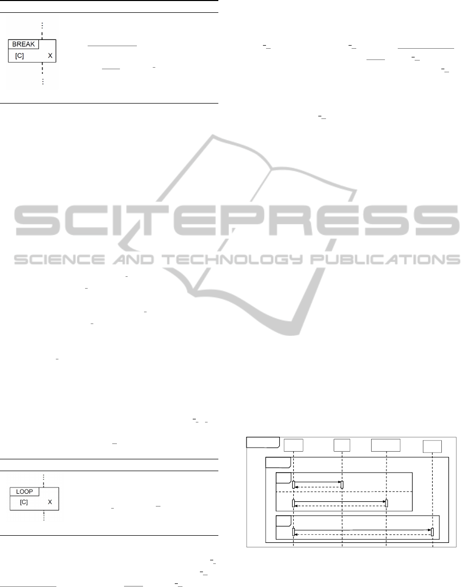
Rule 3.6 Rule for BREAK.
→
stateCopy(C);
if C then
T(X);break.i -> Skip
else Skip
then X is performed and the remainder of the con-
text of the BREAK is discarded. Otherwise, X is not
executed and the control goes to the context outside
the BREAK. However, when BREAK is used inside
the context of another combined fragment, only the
remainder of the operand that encloses the BREAK
is discarded instead of the entire diagram. Another
distinguishing characteristic of its semantics states
that a BREAK fragment should always cover all life-
lines that attend the enclosing context (for instance,
a BREAK inside a PAR should cover all lifelines in-
volved in the parallel composition). We introduced
the auxiliary channel break.i to signal the end of
the BREAK, where i uniquely identifies a particular
BREAK. Outside the scope of the BREAK there are
exception handlers like [|break.i|> Skip: when-
ever the event break.i happens, the diagram behaves
like Skip and ends the execution of that context (see
Rule 3.2). As a BREAK spans over all lifelines, the
event break.i belongs to the alphabet of all lifelines.
3.6 Loop
Rule 3.7 describes the behaviour of the LOOP, which
is denoted by the CML recursive action LOOP j (j is
the unique identifier for the loop) together with the
BREAK handler [|break.k|> Skip .
Rule 3.7 Rule for LOOP.
→
LOOP_j [|break.k|> Skip
The standard LOOP fragment, denoted LOOP j,
is defined as the recursive action LOOP j =
stateCopy(C); if C then (T(X); LOOP j) else
Skip, where C is a Boolean expression and X is the
body of the loop. If either C is evaluated to false or
X raises a BREAK, then the loop stops. The LOOP
combined fragment also allows some variations.
For instance, it accepts arguments that determine
the maximum number of iterations. For example,
LOOP:(3) states that the corresponding fragment
should execute at most three times. In this case,
LOOP j is defined as LOOP j(3,i) = stateCopy(C);
if (i <= 3 and C) then (T(X);LOOP j(3,
i+1)) else Skip. The first argument of LOOP j is
the number of iterations and the second argument is
a counter for the iterations (always initialised with
value 1 in the invocation of such an action). Rule 4.6
assumes that LOOP j produces all possible variations
of the LOOP.
4 CASE STUDY
In this section, we illustrate the application of the
rules presented in Section 3. We also give a flavour of
how the CML translation of a Sequence Diagram can
be combined with the translations of other diagrams.
In our example, we consider a scenario based on an
emergency response system of systems composed of
the Police, the Ambulance and the Fire Department
working together. We describe the scenario in which
the Police sends a press release to the media about the
casualties of a fire incident. This particular scenario
illustrates the use of loops, breaks, and the sequen-
tial and the parallel operators. The Sequence Diagram
depicted in Figure 3 shows that the Police collects in-
formation on casualties in parallel with both the Fire
Department and the Ambulance. If the data are cor-
rect (i.e. Police.checked evaluates to true), then the
Police sends a press release to the Media and the ex-
ecution finishes by breaking the loop. Otherwise, the
Police tries to communicate with the Fire Department
and the Ambulance a few other times (5 at most).
Police Fire Ambulance
Media
loop:(5)
break
par
sd fireIncident
[Police.checked]
2. collectCasualties()
1. collectCasualties()
3. pressRelease()
Figure 3: Emergency Response Scenario.
In order to translate this diagram into CML, we
first apply Rule 3.1, which gives us the following
CML process.
chanset
Hidden = {|join,break,endInteraction|}
AFormalSemanticsforSequenceDiagramsandaStrategyforSystemAnalysis
321

process fireIncident = sd_ID, pol_ID, fire_ID,
amb_ID, media_ID : ID @ begin
actions
Police_def = T(Police)
Fire_def = T(Fire)
Ambulance_def = T(Ambulance)
Media_def = T(Media)
@ let Lifelines =
{|(Police_def, α(Police def)),
(Fire_def, α(Fire def)),
(Ambulance_def, α(Ambulance def)),
(Media_def, α(Media def))|}
within (|| (A,CS): Lifelines @ [CS] A);
endInteraction.sd_ID \ Hidden
end
We now translate each lifeline. For this translation,
we have assigned arbitrary numbers for the identi-
fiers of the messages and the combined fragments: the
messages are identified as 1, 2 and 3 (see Figure 3),
while the identifiers for the LOOP, the PAR, and the
BREAK are assigned numbers 4, 5, and 6, respec-
tively. Regarding the blocks, we assigned the identi-
fiers pol ID, amb ID, fire ID, and media ID for the
Police, Ambulance, Fire, and Media, respectively.
Let us start by translating the Police lifeline. At
the top-level, the Police lifeline matches the rule for
a LOOP (Rule 3.7).
Police_def = LOOP_POL(5,1) [|break.6|> Skip
LOOP_POL(m,i) =
if (i <= m) then
(T(LOOP BODY POL);LOOP_POL(m,i+1))
else Skip
The recursive function LOOP_j in Rule 3.7 is in-
stantiated as LOOP POL, while X is being called
LOOP BODY POL. As the body of the loop runs a
PAR and a BREAK in sequence, the translation of
LOOP BODY POL results from the application of the
rules for sequential composition (Rule 3.2), parallel
composition (Rule 3.5), BREAK (Rule 3.6), and
synchronous message sending (Rule 3.3).
LOOP_BODY_POL = (((
(startCollectCasualties.1.pol_ID.fire_ID ->
endCollectCasualties.1.pol_ID.fire_ID -> Skip)
|||
(startCollectCasualties.2.pol_ID.amb_ID ->
endCollectCasualties.2.pol_ID.amb_ID -> Skip)
); join.5 -> Skip);
(getPolice.checked.pol_ID?checked -> Skip);
if checked then
((startPressRelease.3.pol_ID.media_ID ->
endPressRelease.3.pol_ID.media_ID -> Skip);
break.6 -> Skip)
else Skip)
The communications occur with pairs of messages
(the message itself followed by its acknowledge-
ment). The first pair refers to the communication
from the Police with the Fire Department. It is
exchanged in parallel with the communication
between the Police and the Ambulance. Once
these communications take place, the Police checks
if the data are correct. As we have a guard, we
need to collect the value that will be verified
in the constraint (function stateCopy(C) becomes
getPolice.checked.pol_ID?checked -> Skip,
which means getting the value from attribute checked
of the block Police whose instance is pol_ID). If
the guard is true, then the Police sends the press
release to the media, waits for its acknowledgement
and breaks the loop.
The Fire and the Ambulance lifelines are trans-
lated to a loop specification similar to LOOP POL
above. However, the body of their loop is slightly
different from LOOP BODY POL. The body of the loop
of Fire is shown below.
LOOP_BODY_FIRE =
(((startCollectCasualties.1.pol_ID.fire_ID ->
endCollectCasualties.1.pol_ID.fire_ID ->
Skip); join.5 -> Skip);
(getPolice.checked.pol_ID?checked -> Skip);
if checked then
break.6 -> Skip
else Skip)
We omit the body of the loop of Ambulance as it is
similar to LOOP BODY FIRE.
The Media lifeline runs a loop whose body is
a BREAK. As the loop has a structure similar to
LOOP POL, we omit its specification. The body of the
loop of MEDIA is shown below.
LOOP_MEDIA_BODY =
(getPolice.checked.pol_ID?checked -> Skip);
if checked then
((startPressRelease.3.pol_ID.media_ID ->
endPressRelease.3.pol_ID.media_ID -> Skip);
break.6 -> Skip)
else Skip
Once the complete CML has been produced, we
can animate it, or perform a formal verification anal-
ysis using its traces. Such analysis aims at using Se-
quence Diagrams to describe valid scenarios (traces)
that should be possible to happen in the other SysML
diagrams, as illustrated by Figure 1.
In what follows, we show two traces generated
from the Sequence Diagram in Figure 3. For con-
ciseness, we replace the messages by startN or endN,
where N is the message identifier.
• hstart1, start2, end2, end1, start2, end2, start1,
end1, start3, end3i
• hstart2, end2, start1, end1, start3, end3i
We can verify if these traces are consistent with the
ones generated by other diagrams. If the traces of the
SD cannot be exercised in the other diagrams, there is
an inconsistency in the SysML model.
MODELSWARD2014-InternationalConferenceonModel-DrivenEngineeringandSoftwareDevelopment
322

Thus, the designer may use Block, State Machine
and Activity Diagrams to model the overall behaviour
of the system. We call this set of models the sys-
tem design. Sequence Diagrams are used to model
correct flows of events in the system, and we can
call them valid traces. Once we have the CML pro-
cesses from both the system design (SYS) and valid
traces (TRC), we can verify that both are deadlock
free using the CML model checker. After deadlock
freedom is verified separately for SYS and TRC, we
can combine both SYS and TRC in parallel and syn-
chronise them in the visible channel events of the Se-
quence Diagram: SYS [|α(TRC)|] TRC. We can now
run a deadlock-freedom verification in order to check
the consistency of the system design with respect to
its traces. If a deadlock happens, a trace of the se-
quence diagram cannot be reproduced by the system
design. Moreover, the counter-example produced by
the model checker can be presented as a Sequence Di-
agram by simply transforming a trace into a diagram.
This series of verifications can uncover many design
problems earlier in the development life cycle.
5 RELATED WORK
In this section, we describe some previous works con-
cerning the formal semantics of Sequence Diagrams.
Storrle (Storrle, 2004) presents an exhaustive
work on formalising Sequence Diagrams using trace
semantics. Many constructs used in UML 2, includ-
ing combined fragments, are covered. Storrle’s se-
mantics allows one to reason about refinement, con-
currency and time restrictions. Haugen et al. (Haugen
et al., 2005) propose an approach based on a trace
semantics in which refinement is used as a founda-
tion for compositional analysis. Lund (Lund, 2007)
gives an operational semantics for the Haugen’s de-
notational semantics. In both semantics, loop with
constraint and the BREAK fragment are not covered.
Cavarra (Cavarra and K
¨
uster-Filipe, 2005) proposed
a technique using templates to express liveness prop-
erties in UML Sequence Diagrams and showed that
some of them cannot be expressed with assert or
negate combined fragments. Abstract state machines
are used to enrich the sequence diagram in order to
express such properties. Dan and Danning (Dan and
Danning, 2010) present an approach to semantic map-
ping specified using QVT (OMG, 2005) relations to
CSP (Hoare, 1985). In their work, very few con-
structs of UML 2 are covered. Cengarle (Cengarle
and Knapp, 2005) gives an operational semantics for
Sequence Diagrams focusing on negative and positive
fragments. Rules are given for each of the operators
specifying whether a trace positively or negatively
satisfies a fragment with that operator. Knapp and
Wuttke (Knapp and Wuttke, 2007) provide an oper-
ational semantics based on automata, while Eicher et
al. (Eichner et al., 2005) use multivalued nets, which
are a specific kind of Petri nets that allow parametri-
sation of messages and Interactions. Most of their for-
malisations are described textually.
Most of these works differ among themselves with
respect to the number of constructions covered, the
semantics of constructions whose official meaning is
vaguely defined, and the semantic domain used in
the formalisations. Micksei and Waeselynck (Micskei
and Waeselynck, 2011) have provided an excellent
survey on existing semantics and their decisions. Ta-
ble 1 presents a comparison of the coverage of our
formalisation with related work in the available liter-
ature. The top row contains all the features that we
cover: InteractionUse (IU), Guards (GD), the Com-
binedFragments for parallel (PA), strict sequencing
(ST), alternatives (AL), option (OP), loop (LP), break
(BK), critical region (CR), state invariant (SI), asyn-
chronous message (As) and gates (Gt). The X indi-
cates that the feature is covered by the work, and ×
indicates it is not.
None of the related works aim to perform consis-
tency verification among SysML structural and be-
havioural diagrams. Some approaches try to check
consistency of a maximum of two types of UML dia-
grams (Gongzheng and Guangquan, 2010; Rasch and
Wehrheim, 2003).
6 CONCLUSIONS
We proposed a formal semantics for SysML Sequence
Diagrams. This semantics is built on translation rules
from Sequence Diagrams to the Compass Modelling
Language (CML). It covers sophisticated elements of
Sequence Diagrams like parallel composition, break,
and loop, which are not completely addressed by most
existing approaches. We have actually defined the se-
mantics of a larger set of constructions, described in
more detail elsewhere (Miyazawa et al., 2013).
The main aim of our semantics is the verification
of traces of the whole system modelled by a repre-
sentative set of diagrams. The semantics of these di-
agrams is currently under development. This cross-
diagram verification provides a consistency check of
a model from the structural and the behavioural per-
spectives simultaneously.
We presented a case study that uses elaborated
constructions like loops, breaks and parallel compo-
sition and that captures the interaction among differ-
AFormalSemanticsforSequenceDiagramsandaStrategyforSystemAnalysis
323
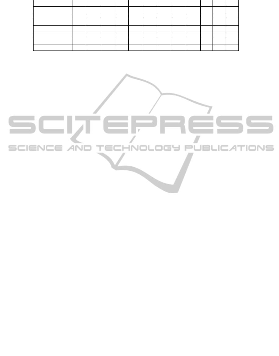
Table 1: Coverage comparison.
IU GD PA ST AL OP LP BK CR SI As Gt
Storrle X × X X X X X X X × X ×
Haugen et al. X X X X X X X × × X X X
Cavarra et al. × X X X X × × × × X X ×
Dan et al. × X × X X X X × × × X ×
Cengarle et al. × × X X X X X × × × X ×
Knapp et al. × X X X X X X × × X X ×
Eichner et al. X X X X X X X X X X X X
ent entities. Although our focus is on system of sys-
tems modelling, we believe our semantics can be gen-
eralised to other domains, as the UML and SysML
semantics for Sequence Diagrams are the same.
Regarding future work, we plan to implement our
translation rules in the Artisan Studio tool
2
, which is a
tool-set for UML/SysML Modelling. We also plan to
develop more elaborate case studies in order to check
consistency across several diagrams in SysML.
ACKNOWLEDGEMENTS
This work was supported by the EU FP7 project
COMPASS and the National Institute of Science
and Technology for Software Engineering (INES)
3
,
funded by CNPq and FACEPE (grants 573964/2008-
4 and APQ-1037-1.03/08).
REFERENCES
Cavarra, A. and K
¨
uster-Filipe, J. (2005). Combining se-
quence diagrams and ocl for liveness. Electron. Notes
Theor. Comput. Sci., 115:19–38.
Cengarle, M. V. and Knapp, A. (2005). Operational seman-
tics of UML 2.0 interactions. Technical report, Tech-
nische Universitt Mnchen and Ludwig-Maximilians
Universitt Mnchen.
Dan, L. and Danning, L. (2010). Towards a formal behav-
ioral semantics for UML interactions. In Proceedings
of the 2010 Third International Symposium on Infor-
mation Science and Engineering, ISISE ’10, pages
213–218. IEEE.
Eichner, C., Fleischhack, H., Meyer, R., Schrimpf, U., and
Stehno, C. (2005). Compositional semantics for UML
2.0 sequence diagrams using Petri Nets. In SDL Fo-
rum, volume 3530 of LNCS, pages 133–148. Springer.
Fitzgerald, J. and Larsen, P. G. (2009). Modelling Systems:
Practical Tools and Techniques in Software Develop-
ment. Cambridge University Press.
Gongzheng, L. and Guangquan, Z. (2010). An approach to
check the consistency between the UML 2.0 dynamic
2
Artisan Studio at http://www.atego.com/products/artisan-
studio/
3
http://www.ines.org.br
diagrams. In 5th International Conference on Com-
puter Science and Education (ICCSE), 2010, pages
1913 –1917.
Haugen, O., Husa, K. E., Runde, R. K., and Stolen, K.
(2005). Stairs towards formal design with sequence
diagrams. Software and System Modeling, 4(4):355–
367.
Hoare, C. A. R. (1985). Communicating and Sequential
Processes. Prentice Hall.
Jamshidi, M. and Jamshidi, M. (2009). Systems of Sys-
tems Engineering: Principles and Applications. CRC
PressINC.
Knapp, A. and Wuttke, J. (2007). Model checking of UML
2.0 interactions. In Models in Software Engineering,
volume 4364 of LNCS, pages 42–51. Springer Berlin
Heidelberg.
Lund, M. S. (2007). Operational analysis of sequence dia-
gram specifications. Ph.D. Thesis, University of Oslo.
Micskei, Z. and Waeselynck, H. (2011). The many mean-
ings of uml 2 sequence diagrams: a survey. Softw.
Syst. Model., 10(4):489–514.
Miyazawa, A., Lima, L., Cornelio, M., Iyoda, J., and Caval-
canti, A. (2013). Final Report on Combining SysML
and CML. Technical Report D22.4, COMPASS De-
liverable.
Object Management Group (2012). OMG Systems Mod-
eling Language (OMG SysML
T M
). Technical report,
Object Management Group. OMG Document Num-
ber: formal/12-06-02.
OMG (2005). MOF QVT Final Adopted Specification.
OMG.
Rasch, H. and Wehrheim, H. (2003). Checking consistency
in UML diagrams: Classes and state machines. In For-
mal Methods for Open Object-Based Distributed Sys-
tems, volume 2884 of LNCS, pages 229–243. Springer
Berlin / Heidelberg.
Storrle, H. (2004). Trace semantics of interactions in uml
2.0. Technical report, Institut fr Informatik, Ludwig-
Maximilians-Universitt Mnchen.
Woodcock, J., Cavalcanti, A., Coleman, J., Didier, A.,
Larsen, P. G., Miyazawa, A., and Oliveira, M. (2012).
CML Definition 0. Technical Report D23.1, COM-
PASS Deliverable.
MODELSWARD2014-InternationalConferenceonModel-DrivenEngineeringandSoftwareDevelopment
324
