
Portable OCT and its Industrial Application
Simple OCT for Industrial Use and Basic Health Care
Tatsuo Shiina
Graduate School of Advanced Integration Science, Chiba University,1-33 Yayoi-cho, Inage-ku, Chiba, Japan
Keywords: OCT (Optical Coherence Tomography), Industry, Health Care, Dentistry, Skin.
Abstract: Portable OCT; Optical Coherence Tomography has been developed for industrial use. This portable OCT is
time-domain type and it is evolved independently from the medical OCT in terms of product cost, system
size, flexibility, and its concept. To realize the unique concept, the new scanning mechanism was devised,
which is consisted of a rotating corner-reflector and a fixed mirror. Its scanning rate is not so high
(<200scan/s), while its measurement range can be enlarged easily. The Spectra-domain OCTs such as
Fourier-domain and Swept-source OCTs needs signal processing to obtain the information in the depth
direction. Their resolution depends on the scanning range and the sampling-rate. The time-domain OCT has
the feature that the resolution only depends on the spectrum width of the incident beam in isolation from the
measurement range. The depth information can be derived from the measured data easily and directly. The
system structure of the portable OCT is elastic in viewpoints of design of the optical prove and the
measurement range, and it is applied in various fields to date. Industrial use, educational aim, and basic
health care are its applications. In this report, the concept and the technical feature of the portable OCT are
mentioned. The concrete applications are introduced to represent the flexibility of the portable OCT, too.
1 INTRODUCTION
The optical sensors has been utilized for a long time
to measure and to diagnose the condition and the
appropriate structures of industrial materials. Here,
the optical sensors are interferometer, optical
displacement meter, moire inspection, stereoscopy,
holography, and so on. Especially, after the
innovation of laser, these devices and methods have
an advantage of high resolution in comparison with
the other sensing methods such as ultrasonic or
electrical measuring methods. The interior
monitoring of targets or materials is no less
important than the external form. The interior
structure measurement is fundamental. Clack,
bubble and uneven concentration can be visualized
by the interior monitoring of the optical sensors.
OCT, optical coherence tomography, is a low
coherence interferometer. (Huang 1991; Schmitt,
1999) The principle of measurement is the same
with white light interferometer. The white light
interferometer, however, mainly measures the
external form and displacement of the sample, while
OCT obtains the cross-sectional image. OCT
progressed in ophthalmology field. Its development
is started in the 2000s. Its technology and product’s
value are sufficiently matured.(Jiao, 2005; Rosa,
2007))
This ophthalmologic OCT, however, cannot
dominate to the industrial applications up to now.
The industrial OCT has large needs. (Goode, 2009;
Merken, 2011; Song, 2012; Wurm, 2007) Though it
is too expensive to install into industrial fields, it is
not only the reason to prevent its prevalence. The
ophthalmologic target, that is human eye, has the
typical size and features, and the manufacturer can
fix the specification of ophthalmologic OCT. In
other words, the system specification of
ophthalmologic OCT is optimized due to the human
eye. By this consideration, the high speed and the
high resolution are current trends of the
ophthalmologic OCT development. In the industrial
fields, there are various kinds of targets. Its size,
material, structure and measurement point are
different individually. The optical probe, which
throws the incident beam to the target, should be
changed due to the target, too. There are many
restrictions to adapt the ophthalmologic OCT to the
industrial fields. It will be better that the system is
simple, compact, robust and low cost. To apply the
83
Shiina T..
Portable OCT and its Industrial Application - Simple OCT for Industrial Use and Basic Health Care.
DOI: 10.5220/0004712200830090
In Proceedings of 2nd International Conference on Photonics, Optics and Laser Technology (PHOTOPTICS-2014), pages 83-90
ISBN: 978-989-758-008-6
Copyright
c
2014 SCITEPRESS (Science and Technology Publications, Lda.)

OCT technology to the industrial use, the system
should have flexibility to the various kinds of
targets. Its approach was started from the different
viewpoint with the development of the
ophthalmologic OCT.
The authors fixed such a concept of the industrial
OCT by 2000, and its portable one was developed in
2009. The system has a unique feature to meet the
industrial needs. The targets of an early date of the
industrial OCT are interior monitoring of industrial
materials, that is, glass, plastic, polymeric films. In a
half-decade, the targets spread not only in industrial
fields, but also expands to plant/food fields and basic
health care fields. In this report, the concept of the
portable OCT is explained and its actual applications
are introduced.
2 CONCEPT
The current OCT has some variations for the interior
diagnosis. Spectral domain OCTs including Fourier
domain OCT and swept source OCT is a technical
method to abandon the scanning in the depth
direction. They become high-speed and high-
resolution. These methods, however, fix their
measurement range and resolution due to the
characteristics of the light source, and it is hard to
change them for the targets. The high-resolution
needs the optical probe to be solid. The flexibility of
the measurement will be lower. The ophthalmologic
OCT is specialized for the human eye, while the
flexibility of the system configuration and the
measurement will be essential for the industrial
application, in which the targets will change its size
and specification.
The portable OCT for industrial use should cover
the various kinds of targets. It is different viewpoint
from the ophthalmologic OCT. The system is
desirable to change the following terms due to the
target.
Measurement range
Working distance of the optical probe
Scanning speed and repetition rate
Measurement range should be enlarged or be shorten
due to the target. The working distance of the optical
probe is better to have redundancy to expand or to
shorten it owing to the measurement target, too. The
scanning speed will be changed by the observation
method whether it is fixed-point measurement or
cross-sectional imaging. The former gives the
information of length (depth), while the latter is an
imager. The targets of industrial application are from
transparent materials such as glass, plastic and
polymeric film to scattering or absorbing materials
such as paper, paint, semi-conductor material and
biological tissue. The sensitivity of OCT
measurement will be sometimes too high, and the
strong reflection from the target may lower or
influence dynamic range of a detector. The
sensitivity should be changed due to the target, too.
The background optical noise, which does not
contribute to the interference, is also reflected by the
target surface. It should be removed.
At the viewpoint of redundancy, compactness
and low cost, we have developed the time-domain
type OCT (TD-OCT). Its resolution of the
measurement is uniquely decided by the spectrum
width of the low-coherent light source. The
measurement range and the working distance can be
fixed without relying on the resolution. As the
measurement data directly reflects the interior
structure, it makes the ensuring judgment easy.
3 PORTABLE OCT SCANNER
TD-OCT needs the mechanical scanning to move the
interference point in the depth direction. Typical
TD-OCT utilizes the piezoelectric transducer to
generate beat frequency of the interferogram. The
scan in the depth direction is conducted by another
scanning stage. This method is hard to speed up with
stable scanning. The stability of scanning depends
on the stage accuracy. In consequence, the long-path
scanning stage has the solid platform to keep the
accuracy. For the industrial use, the measurement
sample is often hard to fix its position precisely. It is
also difficult to shorten the distance between the
sample and the measurement probe. As a result, the
industrial OCT should have the flexibility in the
working distance and the measurement range
designs. The probe design and the scanning speed
should be optimized for each target.
The repetitive scanning motion should be stable,
too. In this study, the long optical path scanning
mechanism was developed as shown in Fig. 1. It
consists of a rotating corner reflector and a fixed
mirror. The scanning range depends on the rotation
radius of the reflector. The scanning speed
(repetition rate) is variable due to the rotation speed
of the reflector. The optical path length is derived by
the following equations.(Shiina, 2003)
Calculation examples of the optical path change
and the beat frequency of the interferogram are
shown in Fig. 2. The rotating radius and speed of the
reflector are 10mm and 50rps (= 3000rpm),
PHOTOPTICS2014-InternationalConferenceonPhotonics,OpticsandLaserTechnology
84
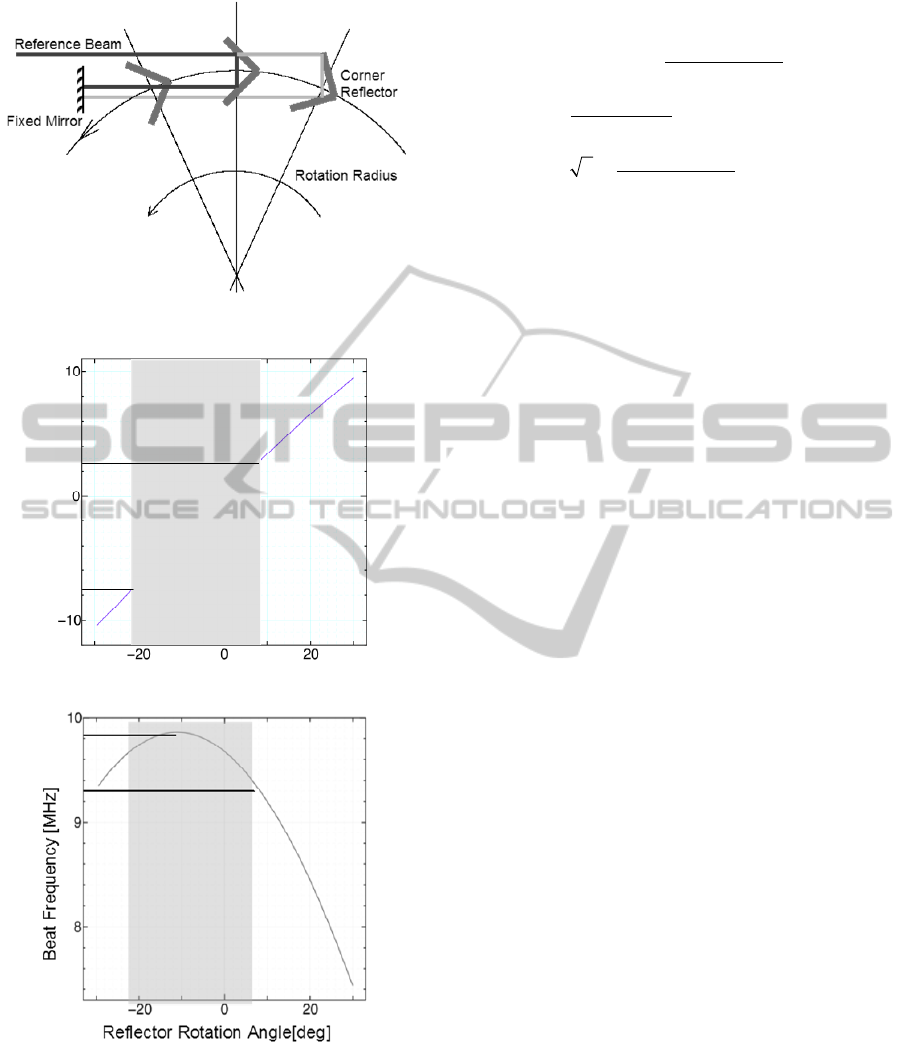
Figure 1: Long path scanning algorism.
(a) Optical path difference
(b) Beat frequency shift
Figure 2: Optical characteristics of scanning algorism.
respectively. The gray area in each graph indicates
the optical path difference of 10mm. The rotating
corner reflector generates the quasi-linear motion.
The divergence from the linear motion is 1-3%
within the rotation angle of +/-20 degrees. The
(1)
interferogram changes its frequency about 1MHz
within the above rotation range.
The portable OCT scanner is composed of SLD
light source module, optical fiber unit, motor unit for
optical path change and detector circuit as shown in
Fig. 3. The SLD light source is with a fiber optical
pigtail, witch is specially fabricated by Anristu Co.
Ltd. Its power is 3mW [max]. Its wavelength is
0.8m or 1.3m and its spectrum width is <60nm.
The resolution of TD-OCT is defined with the
spectrum width of the light source, and it became 6-
8m for the portable OCT. This SLD light source
does not have a cooler. A radiator can be stable
when the output of the optical power is refrained. A
radiator cooling fun is used for long time operation
when the output closes to the maximum (a few
milliwatt). The fiber assembly is specially
developed, too. It consists of a 2x2 fiber coupler and
two collimators, for fundamental structure. Optical
probe and reference ports have collimators. The
optical probe has the other lens optics due to the
target or optical arrangement. The detector circuit
catches the interference signal with a detector. It
outputs the interferogram signal and its envelope
signal through an electrical filter and an amplifier.
The digitized signals are gathered in PC via an
oscilloscope or an A/D interface card. The example
of the concrete setup is summarized in Table 1. The
scanning range is about 12mm when a reflector
rotates at the radius of 10mm. The scanning speed is
25scan/s. Position accuracy is <1m. The
divergence from the linear motion is able to correct
by using the equation (1). Figure 4 shows the
snapshot of the portable OCT scanner. Its size is
120mm x 70mm x 160mm. It can drive with a DC
power supply or a battery.
The wavelength, measurement range, and
scanning speed are fixed due to the target, while the
optical probe should be also designed individually.
The optical probe arranges the working distance
between the probe edge and the target. It receives
the backscattering light from the target with the
adequate numerical aperture (N.A.). It is designed
from 0 (parallel beam) to 0.3 due to the target. The
plate-like target is measured with narrow
Reflector Rotation Angle[deg.]
Optical Path Difference[mm]
Path _ Di f f er ence
2l
1
l
2
(1 sin 2
)
l
1
(r s)sin
(1 r )(1 cos
)
tan(
/4
)
l
2
l
3
cos(
/4
)
l
3
2s
(1 r )(1 cos
)
sin(
/4
)
PortableOCTanditsIndustrialApplication-SimpleOCTforIndustrialUseandBasicHealthCare
85
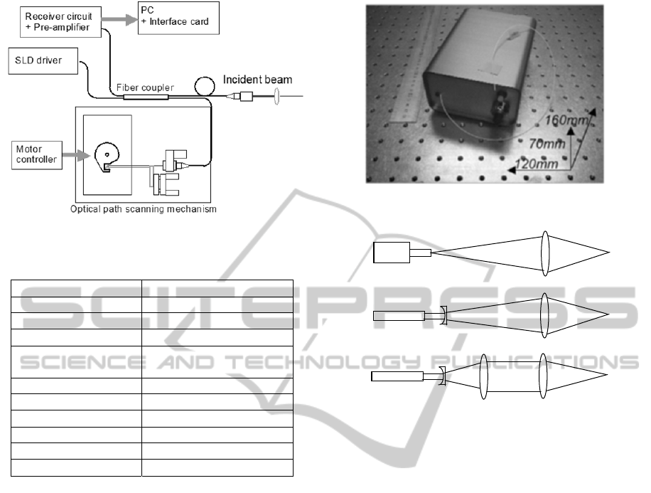
Figure 3: Portable OCT scanner.
Table 1: Portable OCT scanner.
SLD light module Anritsu Co. LTD
Powe
r
3mW [max]
Wavelen
g
th 1.3
m
Spectral width 61.2n
m
Fiber module
Tatsuta Electric wire &
cable Co., LTD
Scannin
g
Mechanism Maxon DC Servo moto
r
Rotation 25 scan/s (1500rpm)
Rotation Radius 10m
m
Resolution 7
m
Position accurac
y
<1
m
Scanning Range 12m
m
N.A., while the high-scattered target such as a
biological tissue is observed with wide N.A. The
spot size of the incident beam becomes 0.5mm
(N.A.=0) and 5m (N.A.=0.3). The measurement
data will be obtained by the combination between
the measurement range due to the reflector and the
depth of field on the optical probe. The design of the
optical probe has several assemblies of lenses as
shown in Fig.5. The differences among them comes
from ease of optical arraignment, simpleness, and
probe size.
4 APPLICATIONS
4.1 Industrial Use
The portable OCT can be installed into a factory as
an embedded equipment of production line. The
targets are the interior monitoring such as clack or
air bubble detection of plastic products, uneven
fluctuation of material or paint, and precision
evaluation of casting. For the industrial use, the
cross-sectional image is not always essential. The
Figure 4: Portable OCT scanner.
Figure 5: Optical probe assembly.
fixed-point measurement and its multi-channel
measurement will accommodate the demands of
industrial use.
Figure 6 shows one of the measurement result,
which is the evaluation of laser fusion on the plastic
plates. (Shiina 2009) The cross sectional image is
obtained by moving the probe in perpendicular
direction against the optical axis (depth direction).
When the laser fusion is conducted perfectly, the
boundary surface between the upper and bottom
plastic plates is disappeared (left image). Then the
scanner does not receive any signal from the fusion
part. The gradations of the reflected interferogram
intensities are observed in the edges of the fusion
part (circle mark in left image). It is dependent on
the spot profile of the laser fusion. On the other
hand, when the fusion is incomplete, the scanner
receives the reflected interferogram signals from the
boundary surface (right image). The obtained OCT
image clearly shows the difference.
Figure 7 shows the measurement result of a
transparent laminated tube (mayonnaise tube). 6-7
layers thin films are layered. Because the differences
between the refractive indices are small, the
interference intensities inside the tube were small.
The layer structure is clearly distinguished. The
thickness of each layer is different from point to
FC Connector
Fiver Collimator
Fiver Collimator
PHOTOPTICS2014-InternationalConferenceonPhotonics,OpticsandLaserTechnology
86
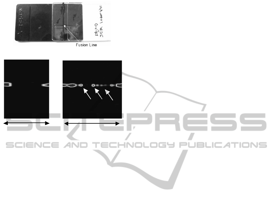
Figure 6: Evaluation of laser fusion on plastic plates.
point of the laminate tube. The individual difference
among products can become a target of portable
OCT, too.
There is a great demand for thickness
measurements of glass, polymeric film, plastic, and
so on. Thickness fluctuation, precision and layer
structures are targets of industrial OCT measure-
ment. Tablet coating (wafer) of medicine was
observed as shown in Fig.8. The merit of portable
OCT is not only direct measurement of the tablet on
a factory line, but also follow-up measurement
through a package because the measurement range is
enough wide. There is no need of the precise
positioning of the target. The wavelength of portable
OCT is near infrared light (0.8 – 1.6 m), and the
influence of color is little. The industrial materials
have wide variety of size (thickness). The portable
OCT can adjust its measurement range to the target
size easily. The flexibility of the portable OCT is
suitable for the industrial use.
The portable OCT is expanded to add the new
function for the industrial demands. In a factory, a
certain procedure will separate on plural lines with
the same routine. In such case, the portable OCT can
separate the optical probe up to the number of the
lines. To make it realize, the optical switch is
installed into a portable OCT. The optical switch
produced by LEONI Co Ltd. was so small that it
could be installed into the case of a portable OCT.
The optical switch changes its channel at every
reflector rotation. When all of the plural probes have
the optical fibers with same lengths, each channel
will conduct the same measurement on plural lines.
When the probes have the different lengths, each
probe has a different task in a line.
The large targets such as combination lens,
crystal block, and liquid tank needs long
measurement range, while the traditional optical
sensor uses a long linear stage to scan the long
range. Such a sensor becomes large, heavy and high
cost. The portable OCT can expand the
measurement range by enlarging the radius of the
rotating reflector. The radius of 60mm, which is the
same size with a compact disc, has the measurement
range of more than 100mm. When the 3 x 3 fiber
coupler can add the reference port and these two
reference ports have different lengths, the
measurement range can enlarge twice as long as a
single reference port.(PCT 2010)
4.2 Basic Health Care
Medical OCTs including ophthalmology, internal
medicine, dentistry and dermatology are productive
applications.(Colston 1998, Leung 2011, Shimada
2012, Todea 2010) The ophthalmologic OCT is
success case to install it into a hospital. On contrary,
the other medical fields are in study phase. The main
impediment is a cost. The introduction of such a
OCT system needs space, cost and a specialist. The
portable OCT started to apply such fields, while it is
not the same direction as medical OCTs. The basic
health care is our purpose.
The portable OCT for dentistry is specialized its
optical probe, which is a stick-like body of the
diameter of 10mm with one-directional auto-stage.
N.A. was controlled to 0.14. The depth of field
becomes 5mm. The caries check is demonstrated
with this portable OCT as shown in Fig.11. The
caries occurs just under the surface of teeth. The
caries of CO could be easily monitored its depth and
area, while the optical probe does not reach to the
intricate position of a teeth at the adequate angle.
Another measurement of dentistry is the boundary
layer detection. The boundary layer between enamel
and dentin is called EDJ (Enamel-Dentin Junction)
and its recognition is important for artificial tooth
and implant placement. The depth of EDJ is about 2
– 3 mm. The portable OCT can visualize it with a
long measurement range as shown in Fig.12.
The human tissue such as skin is a scattering
material for the visible to infrared light. The
propagation depth to obtain the interference signal is
about 0.7 mm for medical OCT. The cross-sectional
image is often reported by medical OCT in
6mm
2.4mm
Complete Fusion
Incom p lete Fusion
Upper plate Upper plate
Lower plate Lower plate
OCT target (Laser-fused plastic plate)
PortableOCTanditsIndustrialApplication-SimpleOCTforIndustrialUseandBasicHealthCare
87
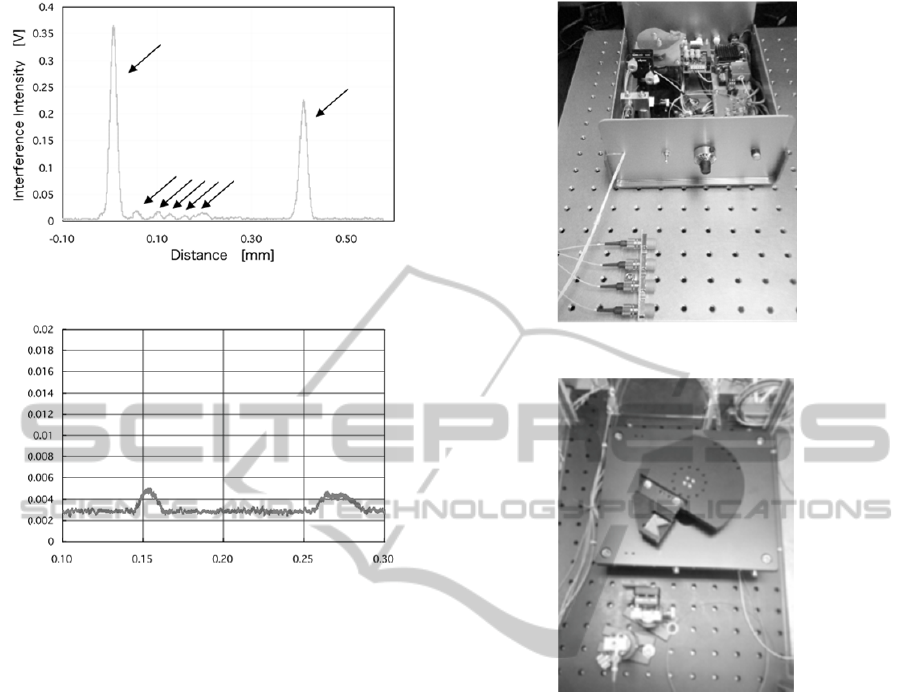
Figure 7: Transparent laminated tube (Mayonnaise tube).
Figure 8: Tablet coating (Thickness measurement).
viewpoint of dermatology.( Koenig 2012, Korde
2007, Mogensen 2009) On another front, the
application for skin measurement is unique for the
portable OCT. The basic health care and cosmetic
perspective are main targets for the portable OCT.
As the portable OCT can be compact and low cost, it
is easy to install it into a cosmetics counter and a
medical interview scene. To adapt the portable OCT
to the skin measurement, the optical probe had high
N.A. of 0.3. The depth of the field becomes about
1mm. The accumulation of about 1,000 times was
conducted for the stable evaluation. The
measurement depth became about 0.5 – 0.6 mm.
Figure 13 shows that the effect of cosmetics for
skin care is visualized by the portable OCT. The
interference intensity was corrected by multiplying
the square of distance. The vertical axis was
represented by log-scale. The normal skin of arm
has two peaks, of which the first is epidermal layer
and the second is dermal layer. The normal thickness
of the epidermal layer is about 0.2 mm. The patient
of Fig.13 had a dry skin. The second layer was not
clear. After the cosmetic care by applying a
foundation and a lotion to the skin, the second peak
from the dermal layer becomes clear. The water
retentivity of the lotion is more effective than that of
Figure 9: Multi-channel probes on a portable OCT.
Figure 10: Long-path scanning reflector on a portable
OCT.
the foundation.
The atopic dermatitis causes the severe damage
on the skin structure. Its damage is not only
exclusive to the epidermal layer, but it also rumbles
into the dermal layer. Figure 14 represents such
damage of the atomic dermatitis. The second peak of
the dermal layer was spoiled. It is clear as compared
with the normal skin. The epidermal layer was
subject to influence, too. It may be no need to be
visualized such skin conditions with a cross-
sectional image. The fixed-point observation such a
stethoscope is useful for a medical interview scene.
The other application is in ophthalmologic field.
Here, the direction of the portable OCT is the basic
health care, too. The fitting of the contact lens and
the combination of the optical power between the
naked eye and the contact lens are the targets for the
portable OCT. Off course, the traditional
ophthalmologic OCT is possible to evaluate such
targets. The current sophisticated OCT, however,
has a firm and big optical probe. To measure the
Distance [mm]
Interference Intensity [V]
PHOTOPTICS2014-InternationalConferenceonPhotonics,OpticsandLaserTechnology
88
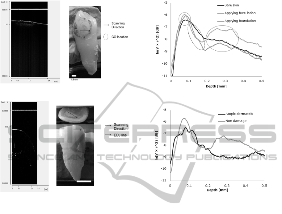
Figure 11: Caries monitoring.
Figure 12: EDJ monitoring.
optical power, the eye should be unblocked to focus
an image. The portable OCT has the flexibility to
design the optical probe because the design of the
optical probe is separated from the resolution factor
and it is designed to unblock the eye.
The some applications mentioned above are now
in clinical practice. To install the portable OCT into
the clinical use as basic health care or cosmetics, the
usability will be pursued. It is because the users will
be not professionals. From this perspective, the
simple structure of the device and the direct
manifestation of the observed information are
important on medical care, especially basic health
care. The portable OCT can be operated with a
buttery. It is useful on rural clinics and developing
countries.
5 CONCLUSIONS
The portable OCT is time-domain type OCT. It is
not latest technology in comparison with the
ophthalmologic OCT. Especially its scanning speed
is much slower than the current ophthalmologic
Figure 13: Skin measurement through cosmetics.
Figure 14: Atopic dermatitis measurement.
OCT. The high scanning speed of the
ophthalmologic OCT, however, is for the real time
observation of the three-dimension or four-
dimension. The high speed signal processing is also
needed to calculate the huge memorized data. The
portable OCT is simple to analyze the obtained data
because the obtained interferogram directly
represents the condition of the interior structure of
the target. The scanning speed is not so high, but it is
enough for most of the industrial applications.
Instead the portable OCT has a feature of wide
flexibility for the designs of the optical probe and
the measurement range. It is adequate for the variety
of the industrial targets.
The applications of the portable OCT for medical
use are the direction to the basic health care and
cosmetics. At viewpoint of the simple operation,
small apparatus and low cost, the portable OCT will
be easily installed into such fields. The cross-
sectional image of teeth is useful to check the caries
and EDJ, while the skin condition can be evaluated
by the fixed-point observations. Easy to use
approach and direct representation of the desired
information are important for the medical interview
scene and formulation of cosmetics.
PortableOCTanditsIndustrialApplication-SimpleOCTforIndustrialUseandBasicHealthCare
89

Up to now, the wide variety of targets were
evaluated by the portable OCT. Their directions are
summarized in Table 2. It shows the targets’
directions with some categories. Now plural
Japanese companies produce the commercial
products of the portable OCT. They are evolved as
built-in system, stand-alone apparatus, and custom-
made device.
Table 2: OCT applications of industrial use.
Industrial use
Displacement, Thickness, Reflective index,
Solution concentration, Crack check, Volume
change, Time response, Vibration, …
Plant and Food processing
Plant Factory, Growth monitoring, Food
processing, Freshness check, Seal check, …
Basic health care and Cosmetics
Ophthalmology, Internal medicine, Visceral
Examination, Dentistry, Dermatology, Cosmetics,
…
REFERENCES
Colston B. W., Evertt Jr, M. J., Silva L. B. D., Otis L. L.,
Stroeve P., and Nathel H., 1998, “Imaging of Hard-
and Soft-Tissue Structure in the Oral Cavity by
Optical Coherence Tomography”, Appl. Opt., 37,
3582-3585.
Goode B. G., 2009, “OCT aims for industrial application,”
Laser Focus World, 45, 41–45.
Grulkowski I., Gora M., Szkulmowski M., Gorczynska I.,
Szlag D., Marcos S., Kowalczyk A, Wojtkowski M.,
2009, “Anterior segment imaging with Spectral OCT
system using a high-speed CMOS camera”, Optics
Express, 17, 4842-4858.
Huang D., Swanson E. A., Lin C. P., Schuman J. S.,
Stinson W. G., Chang W., Hee M. R., Flotte T.,
Gregory K., Puliafito C. A., Fujimoto J. G., 1991,
“Optical coherence tomography”, Science, 254, 1178-
1181.
Jiao S., Knighton R., Huang X., Gregori G., and Puliafito
C., 2005, “Simultaneous acquisition of sectional and
fundus ophthalmic images with spectral-domain
optical cohrence tomography”, Opt. Exp., 13, 444-452.
Koenig K., 2012, “Hybrid Multiphoton Multimodal
Tomography of in vivo human skin”, IntraVital, 1, 11-
26.
Korde V. R., Bonnema G. T., Xu W., Krishnamurthy C.,
Moore J. R., Saboda K., Slayton L. D., Salasche S.J.,
Warneke J. A., Alberts D. S., Barton J. K., 2007,
“Using Optical Coherence Tomography to Evaluate
Skin Sun Damage and Precancer”, Lasers in Surgery
and Medicine, 39, 687-695.
Leung C. K. S., Weinreb R. N., 2011, “Anterior chamber
angle imaging with optical coherence tomography”,
Eye (Lond), 25, 261-267.
Merken P., Vandersmissen R., Yurtsever G., 2011,
“Optical Coherence Tomography: OCT supports
Industrial Nondestructive Depth Analysis”, 47, 2-8.
Mogensen M. and Thrane L., 2009, “OCT imaging of skin
cancer and other dermatological disease”,
Biophotonics, 2, 442-451.
PCT/JP2010/070844.
Rosa C. C., Rogers J., Pedro J., Rosen R., and Podoleanu
A., 2007, “Multiscan time-domain optical coherence
tomography for retina imaging”, Appl. Opt., 46, 1795-
1808.
Schmitt J. M., 1999, “Optical coherence tomography
(OCT): A Review”, IEEE J. Quantum Electron., 5,
1205-1215.
Shiina T., Moritani Y., Ito M., and Okamura Y., 2003,
”Long optical path scanning mechanism for optical
coherence tomography”, Appl. Opt., 42, 3795-3799.
Shiina T., Satoshi M., and Honda T., 2009, “Factory Built-
in Type Simplified OCT System for Industrial
Application”, IEEJ Trans. EIS, 129, pp.1276-1281
(written in Japanese).
Shimada Y., Sadr A., Nazari A., Nakagawa H., Otsuki M.,
Tagami J., Sumi Y., 2012, “3D evaluation of
composite resin restoration at practical training using
swept-source optical coherence tomography (SS-
OCT)”, Dental Material Journals, 31, 409-417.
Song G., Harding K., 2012, “OCT for Industrial
Applications”, SPIE Proceedings, 8563, -
Steiner R., Kunzi-rapp K., and Scharffetter-Kochanek K.,
2003, “Optical Coherence Tomography: Clinical
Applications in Dermatology”, Med. Laser Appl., 18,
2459-259.
Todea C., Negrutiu M. L., Balabuc C., Sinescu C., Topala
F. I., Marcauteanu C., Canjau S., Semez G., Podoleanu
A. G. 2010, “Optical Coherence Tomography
Applications in Dentistry”, TMJ, 60, 5-17.
Wurm M., Wiesauer K., Nagel K., Pircher M., Götzinger
E., Hitzenberger C. K., Stifter D., 2007, “Spectral-
Domain Optical Coherence Tomography: A Novel and
Fast Tool for NDT”, IVth NDT in progress, 225-232.
PHOTOPTICS2014-InternationalConferenceonPhotonics,OpticsandLaserTechnology
90
