
A Pattern Language for Use Case Modeling
António Miguel Rosado da Cruz
Escola Superior de Tecnologia e Gestão, Instituto Politécnico de Viana do Castelo,
Av. Do Atlântico, s/n, Viana do Castelo, Portugal
Keywords: Model-Driven Software Engineering, Use Case Modeling.
Abstract: Use case driven software development typically starts with abstract problem domain descriptions of how the
users see themselves using the system being developed, and entails a series of iterative refinement steps that
incrementally detail the user stories/use case model, in order to bring those descriptions to the solution
domain. This process tends to produce overcrowded detailed use case models that are difficult to read, but
that are essential to maintain a use case driven approach, during software construction/coding activities.
Business applications typically comprise a set of functions that the users can make on the system. When a
use case driven approach is used to develop business applications those typical business applications’
functions pop-up as use case patterns. This paper presents a set of use case patterns that can be found in
data-centered business applications, and proposes a use case pattern language that can be used together with
standard UML use case language to facilitate the understanding of detailed use case models.
1 INTRODUCTION
Use case driven software development impels
software engineers to follow an approach that is
guided by the system functionality. This approach,
typically starts with high-level problem domain
descriptions of how the users see themselves using
the system being developed, and entails a series of
iterative refinement steps that incrementally detail
the user stories/use case model, in order to bring
those descriptions to the solution domain (Jacobson
et al., 1998). These refinement steps comprise the
simultaneous development of a domain model,
which models the domain entities and the structural
relations between them (Frankel, 2003).
Such a process produces increasingly detailed
use case models and domain entity models that must
be kept consistent with each other (Cruz and Faria,
2009). This process, however, tends to produce
overcrowded detailed use case models that are
difficult to read, but that are essential to maintain a
use case driven approach, during software
construction/coding activities.
On the other hand, data-centered systems, which
constitute the vast majority of business applications,
comprise a set of typical functions that the users can
make on the system. When a use case driven
approach is used to develop business applications
those typical business applications’ functions pop-up
as use case patterns.
Another point to acknowledge is that a use case,
at design level, entails system behavior that is
expected to happen when the use case is performed.
That behavior usually starts to be described in
human language, for each use case. But, as the use
case model becomes more concrete, use cases
become more obvious, and each use case
description/behavior may be inferred from a short
description or from the use case name itself. This
use case behavior acts on a system domain entity
instance or instances (its collaborative entity
classes), so the use case model needs to be closely
related to the system's structural domain model. This
proximity, in the sense that the use case model refers
entities from the domain model, by identifying each
use case main collaborative entity class and other
secondary collaborative classes, demands and
reinforces the need for full consistency between the
two models. Indeed, use case and domain models are
two sub-models of one and the same system model.
The first models a vision of the system functionality,
and the latter models a vision of its structural
features. The vision of the system behavior is, in this
approach, divided between invariant constraints in
the domain model and implicit short “standard”
behaviors in patterns in the use case model (Cruz,
408
Rosado da Cruz A..
A Pattern Language for Use Case Modeling.
DOI: 10.5220/0004720204080414
In Proceedings of the 2nd International Conference on Model-Driven Engineering and Software Development (MODELSWARD-2014), pages 408-414
ISBN: 978-989-758-007-9
Copyright
c
2014 SCITEPRESS (Science and Technology Publications, Lda.)
2010).
This paper identifies the most common use case
patterns found on design-level use case models, and
proposes a pattern language for facilitating design-
level use case modeling.
2 DATA-CENTERED USE CASE
PATTERNS
Use case models must be constructed in close
connection with the system domain model, referring
to its classes and operations. A system use case
model complements the system domain model by
identifying the available system functionality, that is
the CRUD (create/retrieve/update/delete), user-
defined or navigational operations over domain
entities that are available within each use case, and
by identifying the actors (user roles) that have access
to each use case functionality. The data manipulated
in each use case is determined by the domain entity
and/or operation associated with it. In order to
ensure model consistency, several constraints are
posed on the types of use cases and use case
relationships that can be defined (Cruz and Faria,
2009). These constraints define a set of use case
patterns that are typically found in data oriented
(data management) applications.
Two categories of use cases can be distinguished
in the patterns presented in the next subsections
(Cruz and Faria, 2009; Cruz and Faria, 2010):
Independent use cases, can be initiated directly,
and so can be linked directly to actors, which
initiate them;
Dependent use cases, can only be initiated from
within other use cases, called source use cases,
because they depend on the context set by these;
the dependent use cases extend or are included by
the source ones, according to their optional or
mandatory nature, respectively.
2.1 Use Case Patterns
Data oriented applications have as main
functionality the management of stored entities’
information. Operations in such applications
typically include listing the (possibly filtered)
instances of an entity, editing entity properties,
defining or modifying entities’ relationships, etc.,
and may be grouped in the following use case
patterns:
Manage an entity instance;
Manage dependent related entity instances;
Manage independent related entity instances;
Manage dependent related entity collections;
Manage independent related entity collections.
This section presents these typical functionality
patterns, modeled as use case diagrams, taking the
form of use case patterns that can be used in
constructing a system’s use case model.
2.1.1 Manage an Entity Instance
Managing an entity instance typically involves
listing all or some of the existing instances, and
selecting one of those instances for editing
(retrieving its information for visualizing, updating
or deleting it), or creating a new instance.
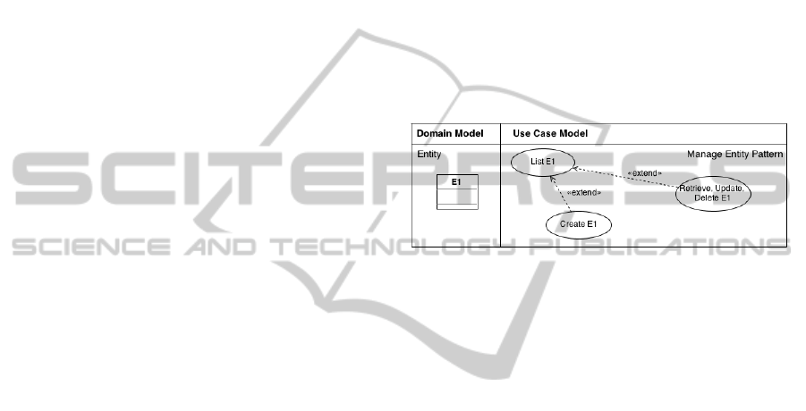
Figure 1: “Manage an entity instance” use case pattern.
“Manage an entity instance” is, thus, a use case
pattern comprising three use cases where use cases
for creating an entity instance (Create E1, in Figure
1) and editing an existing instance (Retrieve,
Update, Delete E1) are dependent of, and extend, the
use case for listing existing instances (List E1).
List E1 may also be extended with a use case for
defining filtering criteria. And, of course, Create E1
might also be directly accessed by actors.
We assume that, as specified in (Cruz and Faria,
2009; Cruz and Faria, 2010), each use case
references an entity through a tagged value, for
consistency between models. All use cases of this
pattern refer to the same entity in the domain model
(E1).
At the end of this section a small example will
illustrate the use of this and other patterns.
2.1.2 Manage Dependent Related Entity
Instances
A dependent related entity instance is an instance of
an entity E2 that has a “one to one” or a “zero-or-
one to one” association with E1 (refer to figure 2).
Managing the instance of E2 associated to a
given instance of E1 typically involves creating a
new related instance (Create Related E2, in Figure
2), or editing the existing related instance (Retrieve,
Update, Delete Related E2).
These two use cases are available from within
APatternLanguageforUseCaseModeling
409
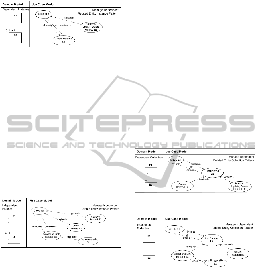
Figure 2: “Manage dependent related entity instance” use
case pattern.
the use case that allows to create or edit the instance
of E1 (CRUD E1, in Figure 2).
“Manage dependent related entity instance” is,
therefore, a use case pattern comprising the three use
cases referred to above, where CRUD E1 references
instance E1, in the case of a “zero-or-one to one”
association between E2 and E1, and it needs to
reference E1 and E2, in the case of a “one to one”
association between the two instances.
The other two use cases need to reference both
instance E1 and E2, because, creating or updating
E2 always demands a related E1.
2.1.3 Manage Independent Related Entity
Instances
An independent related entity instance is an instance
of an entity E2 that has a “one to many” or a “zero-
or-one to many” association with E1.
Figure 3: “Manage independent related entity instance”
use case pattern.
Managing the instance of E2 associated to a given
instance of E1 typically involves linking (Select and
Link Related E2, in Figure 3) or unlinking (Unlink
Related E2) an existing instance of E2, or simply
retrieving its information (Retrieve Related E2).
These three use cases are available from within the
use case that allows creating or editing the instance
of E1 (CRUD E1, in Figure 3).
Use case “Select and Link Related E2” includes
a use case for listing existing instances of E2 not
related to the instance of E1 being managed (List
Unrelated E2).
As a result, “Manage independent related entity
instance” is a use case pattern comprising the five
use cases referred to above, where CRUD E1
references instance E1, in the case of a “zero-or-one
to many” association between E2 and E1, and it
needs to reference E1 and E2, in the case of a “one
to many” association between the two instances.
The other use cases need to reference both
instance E1 and E2, because, creating or updating
E2 may imply a related instance of E1.
2.1.4 Manage Dependent Related Entity
Collections
Dependent related entities are the instances of an
entity E2 that have a mandatory “to one” association
to E1. Managing the collection of instances of E2
associated to a given instance of E1 typically
involves listing all or some of the existing related
instances, and selecting one of those instances for
editing (retrieving its information for visualising,
updating or deleting it), or creating a new related
instance.
Figure 4: “Manage dependent related entity collection”
use case pattern.
Figure 5: “Manage independent related entity collection”
use case pattern.
“Manage dependent related entity collection” is,
hence, a use case pattern comprising four use cases
where use cases for creating a new related instance
(Create Related E2, in figure 4) and editing existing
related instances (Retrieve, Update, Delete Related
E2) extend the use case for listing existing related
instances (List Related E2), which in turn extends or
is included in a use case where E1 is managed
(CRUD E1).
MODELSWARD2014-InternationalConferenceonModel-DrivenEngineeringandSoftwareDevelopment
410
2.1.5 Manage Independent Related Entity
Collections
Independent related entities are the instances of an
entity E2 that have an optional shared “to one” or
“to many” association with E1. Managing the
collection of instances of E2 associated to a given
instance of E1 typically involves listing all or some
of the existing related instances, and selecting one of
those instances for editing (retrieving its information
for visualizing, updating or unlinking it), or selecting
an existing unrelated instance of E2 and link it to E1.
“Manage independent related entity collections”
is, so, a use case pattern comprising five use cases
where use cases for selecting and linking a related
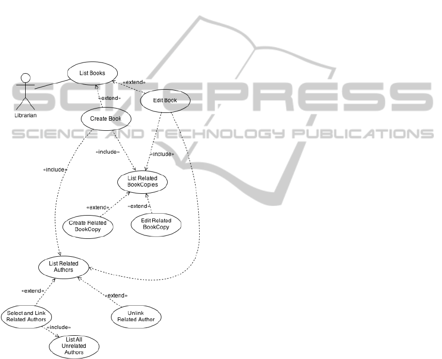
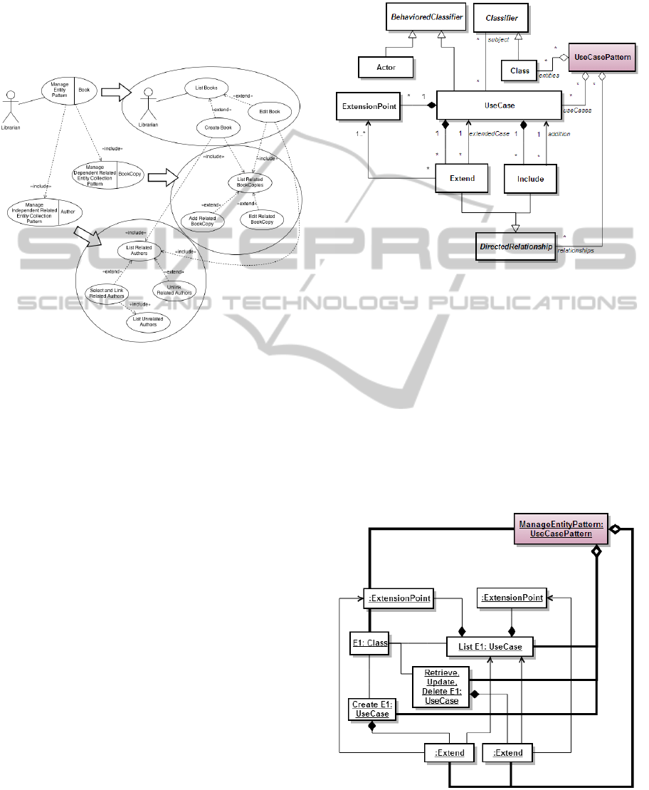
Figure 6: Example of a subset of a librarian’s use cases in
a Library System.
instance (Select and Link Related E2, in figure 5)
and unlinking existing related instances (Unlink
Related E2) extend the use case for listing existing
related instances (List Related E2), which in turn
extends or is included in a use case where E1 is
managed (CRUD E1). Also, use case “Select and
Link Related E2” includes a use case for listing
existing instances of E2 not related to the instance of
E1 being managed (List Unrelated E2).
2.2 Example
Figure 6 shows a small example of a set of use cases
associated to a Librarian actor, from a partial library
system use case model. The librarian is able to list
the library books and, from there, a book may be
selected for edition (Edit Book use case in the
figure) or a new book may be created (Create Book).
Both these use cases include a list of the related
book copies. Of course, use case “Create Book” will
present an empty list, but in both use cases the
librarian will be able to create a new related
bookcopy (Create Related Bookcopy) or edit an
existing one (Edit Related Bookcopy).
When creating or editing a book, the librarian is
also able to list the book’s authors (use case List
Related Authors), and from that list he may select an
existing unrelated author and link it to the book in
question. He may also unlink a currently related
author from the book, making it unrelated.
So, in this example, we can find three of the
previously presented use case patterns, namely:
“Manage Entity” pattern, which refers to entity
Book in the domain model, and addresses listing,
creating and editing Book instances;
“Manage Dependent Related Entity Collection”,
which refers to entity BookCopy, which has a
“many to one” dependent relationship with Book.
This use case pattern addresses listing the
BookCopies related to a selected book, creating a
new BookCopy associated to a book and editing an
existing BookCopy;
“Manage Independent Related Entity Collection”,
which refers to entity Author in the domain model,
which has a “many to many” independent relation
with Book. This use case pattern addresses listing
the authors associated to a selected book, selecting
and linking existing unrelated authors to a book,
and also unlinking authors from a book.
The latter two use case patterns are both included
in the “Manage Entity” pattern.
In the next section we will define a pattern
language that will ease the process of constructing
the use case model, without losing information.
Indeed, it even clarifies some issues by putting in the
diagram the association of each pattern to classes in
the domain model.
APatternLanguageforUseCaseModeling
411
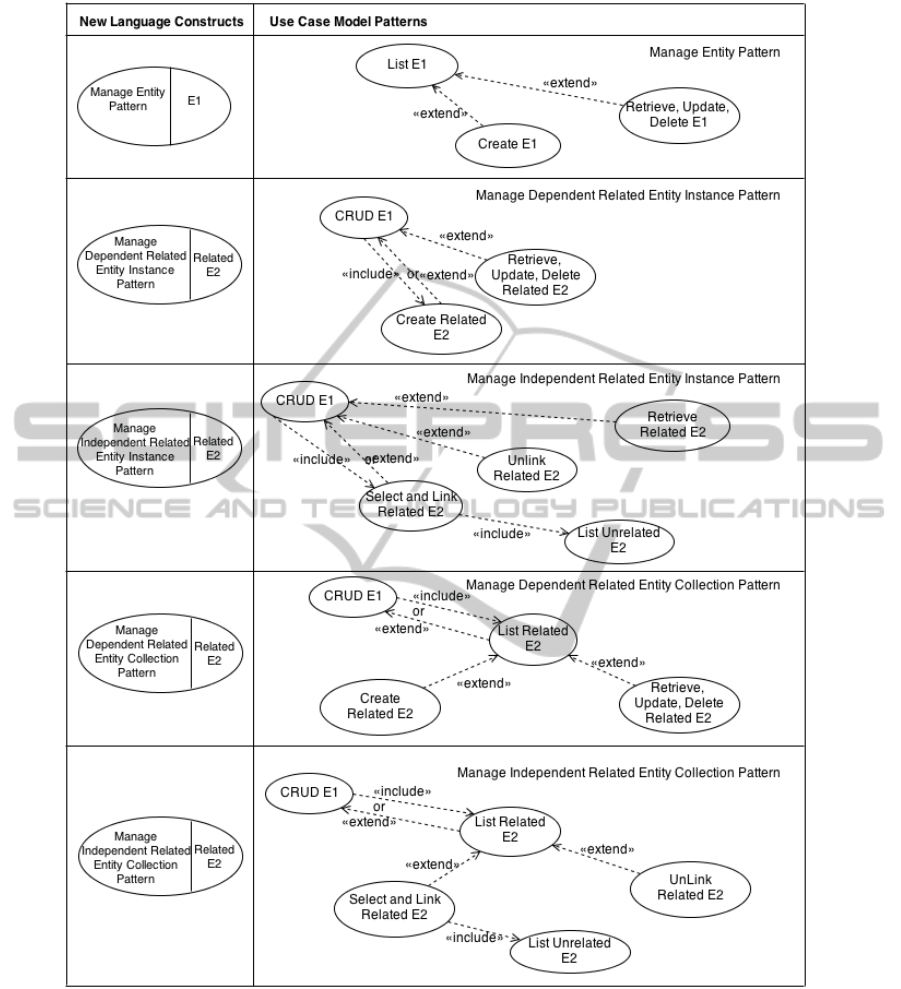
Figure 7: New language constructs and the corresponding use case patterns.
3 A PATTERN LANGUAGE
FOR USE CASE MODELS
A pattern language is a collection of patterns that
build on each other to create a system (Vlissides et
al., 1996; Winn and Calder, 2006). In this section a
modeling language based on the use case patterns
presented above is proposed.
For each one of the five previously identified use
case patterns typically found in data-centered
systems, a new model construct is defined, as
depicted in the table in Figure 7.
Each of these new language constructs identifies
a use case pattern and reveals, in a use case pattern
diagram, the previously hidden associated domain
MODELSWARD2014-InternationalConferenceonModel-DrivenEngineeringandSoftwareDevelopment
412
model entities that were only visible by consulting
the corresponding tagged values in each use case.
Through this new language, use case pattern
models can be constructed. Furthermore, use case
models can include the new constructs because they
have a well defined semantics in terms of standard
use cases.
Figure 8: Comparison between the proposed pattern
language constructs and the traditional use case model, for
the partial Library System example.
Recalling the example in section 2.2, we can now
rewrite the use case model in figure 6, by making
use of the new constructs. This is depicted in figure
8, which also illustrates the correspondence between
the new use case pattern model and the traditional
use case model presented before.
The model in the proposed use case pattern
language can be read as: the librarian actor is able to
manage the library books and, from there, a book’s
bookcopies can be managed in a dependent manner
(every bookcopy must be associated to a book).
Also, the book’s authors may be managed in an
independent manner (authors may not be associated
to a book, or they may be associated to several
books).
4 EXTENDING THE UML
METAMODEL
This section addresses the way the UML metamodel
may be extended, in order to formally include the
concept of a Use Case Pattern. This allows to
formally integrating the previously defined
constructs into use case diagrams, and the
conversion back and forth between use case patterns
and their constituents.
Figure 9: Extending the UML metamodel for use cases
with UseCasePattern.
Figure 9 partially illustrates the concepts used for
modeling use cases, and thus the partial UML
metamodel for use cases, as defined in the UML
2.4.1 superstructure (OMG, 2011). In gray, the
UseCasePattern class and its relations to UseCase,
Class and DirectedRelationship, represent the new
added concept.
The generic Manage Entity Pattern, introduced in
section 3 (refer to Figure 7), would have the aspect
depicted in Figure 10, if represented as an instance
of the extended metamodel.
Figure 10: The generic Manage Entity Pattern as instance
of the extended metamodel.
APatternLanguageforUseCaseModeling
413

The Manage Entity Pattern is composed of three
use cases, two extension relations and references the
classes referenced by the aggregated use cases. And,
as its instance has a concrete graphical symbol, that
may be used as a construct in the use case model
with the same semantics as the aggregated elements
(use cases, use case relations, and referenced
classes). As mentioned before, this allows
substituting one by the others, in a use case model,
simplifying the model by eliminating elements and
substituting them by one, with the same semantics,
which can be understood as being at a higher
abstraction level. This rationale is applicable to all
the other patterns introduced in section 3.
The only constraint that must be observed by
every use case pattern is that the classes (entities)
referenced by the use case pattern must be the ones
referenced by the use cases in the pattern. In OCL,
this could be stated as:
Context UseCasePattern inv:
self.entities->asSet() ==
(self.useCases->collect(subject))
->flatten()
->asSet()
5 CONCLUSIONS
In order to ease the construction of detailed fine
grained use case models, this paper proposes a new
use case pattern language.
The proposed use case pattern language allows
the modeling of fine grained use cases, without
overcrowding the model with use cases and without
losing the relation to the standard UML use case
language. This enables using the proposed use case
pattern language constructs intermingled with the
standard UML use case notation, as every construct
can be converted to a standard UML use case
pattern, and vice-versa.
Notice that the need for a consistent
corresponding domain model is not changed.
However, the proposed language emphasizes the
association between use cases and the corresponding
domain model entities, by stressing each use case
pattern collaborating entity in the graphical
construct.
Future work will further formalize the new
pattern language by addressing the forth and
backwards transformation between models in the
proposed pattern language and standard UML use
case models. Another goal for future work is the
development of a modeling tool that enables use
case modeling, and pattern identification and
substitution in the model.
REFERENCES
Cruz, A. M. R., Faria, J. P., 2009. Automatic generation of
user interface models and prototypes from domain and
use case models. In Proceedings of the ICSoft 2009,
Sofia, Bulgaria, vol. 1, pp. 169–176. INSTICC Press.
Cruz, A. M. R., Faria, J.P., 2010. A Metamodel-based
Approach For Automatic User Interface Generation.
In Proceedings of the 13
th
ACM/IEEE International
Conference on Model Driven Engineering Languages
and Systems (Models 2010), Part 1, LNCS 6394,
pp.256-270, Oslo, Norway. Springer-Verlag Berlin
Heidelberg.
Cruz, A. M. R., 2010. Automatic generation of user
interfaces from rigorous domain and use case models.
PhD dissertation. FEUP, University of Porto, Portugal.
Frankel, D. S., 2003. Model Driven Architecture -
Applying MDA to Enterprise Computing. Wiley
Publishing, Inc., Indianapolis.
Jacobson, I., Booch, G., Rumbaugh, J., 1998. The Unified
Software Development Process. Addison Wesley,
Reading.
OMG, 2011. OMG Unified Modeling Language (OMG
UML), Superstructure. Version 2.4.1. Available in
http://www.omg.org/spec/UML/2.4.1/Superstructure/
Vlissides, J., Coplien, J. and Kerth, N. (editors), 1996.
Pattern Languages of Program Design, Volume 2,
Addison Wesley, Pearson Education, Boston.
Winn, T. and Calder, P., 2006. A Language Designer’s
Pattern Language. Chapter in book Pattern Languages
of Program Design 5. Volume 5, Addison Wesley,
Pearson Education, Boston.
MODELSWARD2014-InternationalConferenceonModel-DrivenEngineeringandSoftwareDevelopment
414
