
Self-learning Voxel-based Multi-camera Occlusion Maps for 3D
Reconstruction
Maarten Slembrouck, Dimitri Van Cauwelaert, David Van Hamme, Dirk Van Haerenborgh,
Peter Van Hese, Peter Veelaert and Wilfried Philips
Ghent University, TELIN dept. IPI/iMinds, Ghent, Belgium
Keywords:
Multi-camera, Occlusion Detection, Self-learning, Visual Hull.
Abstract:
The quality of a shape-from-silhouettes 3D reconstruction technique strongly depends on the completeness
of the silhouettes from each of the cameras. Static occlusion, due to e.g. furniture, makes reconstruction
difficult, as we assume no prior knowledge concerning shape and size of occluding objects in the scene. In
this paper we present a self-learning algorithm that is able to build an occlusion map for each camera from
a voxel perspective. This information is then used to determine which cameras need to be evaluated when
reconstructing the 3D model at every voxel in the scene. We show promising results in a multi-camera setup
with seven cameras where the object is significantly better reconstructed compared to the state of the art
methods, despite the occluding object in the center of the room.
1 INTRODUCTION
Occlusion is undesirable for computer vision appli-
cations such as 3D reconstruction based on shape-
from-silhouettes (Laurentini, 1994; Corazza et al.,
2006; Corazza et al., 2010; Grauman et al., 2003) be-
cause parts of the object disappear in the foreground-
background segmentation. However, in real-world
applications occlusion is unavoidable. In order to
handle occlusion, we propose a self-learning algo-
rithm that determines occlusion for every voxel in the
scene. We focus on occlusion as a result of static ob-
jects between the object and the camera.
Algorithms to detect partial occlusion are pre-
sented in (Guan et al., 2006; Favaro et al., 2003;
Apostoloff and Fitzgibbon, 2005; Brostow and Essa,
1999). However, in these papers occlusion is de-
tected from the camera view itself by keeping an
occlusion map which is a binary decision for each
of its pixels. An OR-operation between the fore-
ground/background mask and the occlusion mask, re-
sults in the input masks for the visual hull algorithm.
The major drawback to this approach is that occlusion
is in fact voxel-related, rather than pixel-related: the
same pixel in an image is occluded when the occlud-
*This research was made possible through iMinds, an
independent research institute founded by the Flemish gov-
ernment.
ing object is located between the object and the cam-
era, but not if the object is placed between the camera
and the occluding object. Pixel-based occlusion de-
tection results in a 3D model which consists of far
more voxels not belonging to the 3D model because
the occluder is also reconstructed and depending on
the position of the person, parts of the occluder are
still left over after subtracting the visual hull of the
occluder (we will show this in Section 5).
Therefore, we propose an occlusion map (one for
each camera) from a voxel perspective, in order to
evaluate each voxel separately. After the occlusion
maps are built, we can use this information and only
evaluate the camera views which are not occluded and
therefore contribute to the 3D model.
We determine occlusion and non-occlusion based
on a fast algorithm of the visual hull concept. In or-
der for the system to work, the occlusion algorithm
requires someone walking in the scene to make oc-
cluded regions appear. Subsets of the different camera
views are used to increase the votes for either occlu-
sion or non-occlusion for each voxel. A majority vote
decides about the final classification.
We also assign a quality factor to the subset of
chosen cameras because the volume of the visual hull
strongly depends on the camera positions. Instead of
counting integer votes, we increment by the quality
factor which depends both on the combined cameras
and the voxel position.
502
Slembrouck M., Van Cauwelaert D., Van Hamme D., Van Haerenborgh D., Van Hese P., Veelaert P. and Philips W..
Self-learning Voxel-based Multi-camera Occlusion Maps for 3D Reconstruction.
DOI: 10.5220/0004723305020509
In Proceedings of the 9th International Conference on Computer Vision Theory and Applications (VISAPP-2014), pages 502-509
ISBN: 978-989-758-004-8
Copyright
c
2014 SCITEPRESS (Science and Technology Publications, Lda.)

In Section 2 we explain the fast visual hull algo-
rithm. Section 3 proposes the self-learning occlusion
algorithm. We determine the quality factor for a cam-
era combination which is used for voting in Section 4.
In Section 5 we show the promising results of our test
setup.
2 FAST VISUAL HULL
COMPUTATION
The visual hull of an object is determined by its sil-
houettes as a result of the foreground-background
segmentation (Kim et al., 2006; Zivkovic, 2004) and
the intrinsically and extrinsically camera calibration
parameters. We use a voxel representation for the vi-
sual hull to reduce computation time. It is required
that all cameras face the same area, called the over-
lapping area, because that is the only area where a 3D
model can be built using all cameras with this imple-
mentation.
2.1 Fast Visual Hull Algorithm
Our fast visual hull algorithm loops over all voxels in
a bounded area. For each voxel, the foreground masks
are evaluated at its projected image coordinates for
each camera. A voxel is part of the visual hull, only if
all projections are classified as foreground. Algorithm
1 shows our fast visual hull implementation.
Algorithm 1: Fast visual hull algorithm.
input: camera calibration, FG/BG-masks, bounded area
output: voxelated visual hull
for all voxel in voxel space do
while voxel occupied and not all camera views evalu-
ated do
lookup the voxel’s projection on next camera view
if projection is foreground then
classify voxel as occupied
else
classify voxel as unoccupied
end if
end while
end for
2.2 Optimization
Within a particular multi-camera setup, the projec-
tions of the voxels are always the same as long as
the cameras do not move. Therefore, we calculate the
image coordinates corresponding to each voxel cen-
ter in the scene in the precomputation phase of our
visual hull algorithm and use a lookup table to deter-
mine the image coordinates. Equation 1 shows how
the voxel center (X,Y, Z) is projected onto the image
sensor, resulting in pixel coordinates (x, y). The pro-
jection matrix P is the product of the intrinsic camera
matrix and the transformation matrix (R|T ).
x
y
1
=
P
z }| {
f
x
0 c
x
0 f
y
c
y
0 0 1
r
11
r
12
r
13
t
1
r
21
r
22
r
23
t
2
r
31
r
32
r
33
t
3
X
Y
Z
1
(1)
Note that this does not lead to an exact reconstruc-
tion because only the center of each voxel is evaluated
making it suitable for solid objects but not for objects
with holes. For each camera the traditional implemen-
tation projects eight points (voxel corners) and eval-
uates all pixels within their convex hull whereas we
only project a single point (voxel center) and evaluate
this pixel value. The major advantage of our approach
is that it increases the speed significantly (more than
8 times faster).
3 SELF-LEARNING OCCLUSION
ALGORITHM
Visual hull algorithms are inherently sensitive to mis-
classified pixels in the foreground-background seg-
mentation, the presence of which is to be expected
when camera views are occluded by one or more ob-
jects. Therefore we propose a self-learning algorithm
which determines for every voxel if it is occluded for
any of the cameras. Hence, the number of occlusion
maps equals the number of cameras in the room.
3.1 Deciding if a Voxel is Occluded
Deciding whether a voxel is occluded or not does not
seem to be an easy task. In previous research, occlu-
sion was determined from pixel perspective but this is
not sufficient because of the following reason. Con-
sider a piece of furniture in the middle of the scene
(e.g. a closet). From the perspective of a particular
camera, a person can stand in front of the furniture
or behind it, resulting in occlusion by the closet in
the latter case. But if we look at the occluding pix-
els from the camera view, we see the pixels are only
occluded when the person stands behind the closet.
When the person stands in front of it, those same pix-
els should not be considered as occluded pixels be-
cause they hold relevant information. Since standard
Self-learningVoxel-basedMulti-cameraOcclusionMapsfor3DReconstruction
503
cameras do not have depth information it is not suf-
ficient to keep track of occluded pixels, therefore we
use occluded voxels.
To decide if there is occlusion, we make some as-
sumptions. One of these assumptions is that there
needs to be a consensus about the occupation of a
voxel in the space. This consensus is only possible
if a minimum number of cameras agree that a voxel
at a certain place in space is occupied. If there are
for example three cameras agreeing there is an ob-
ject at a certain position in space, but the fourth cam-
era does not detect anything there, then we can quite
safely assume that those unseen voxels are occluded
for the fourth camera. However, it is not clear how
many cameras need to agree about this visibility. One
could expect as much as possible, but this will fail if
there is a lot of occlusion because the consensus will
be lacking.
Since it is hard to decide whether a voxel is oc-
cluded for a certain camera, we count votes for both
cases: occluded and non-occluded. Every voxel has
a separate count for each camera for both classes.
The only requirement is that a person needs to walk
around in the scene to make occluded regions appear.
Voxels outside the field of view of the cameras are
directly classified as occluded because these voxels
are out of sight. In the following sections we explain
our detection mechanism for both occlusion and non-
occlusion in detail.
3.1.1 Visible
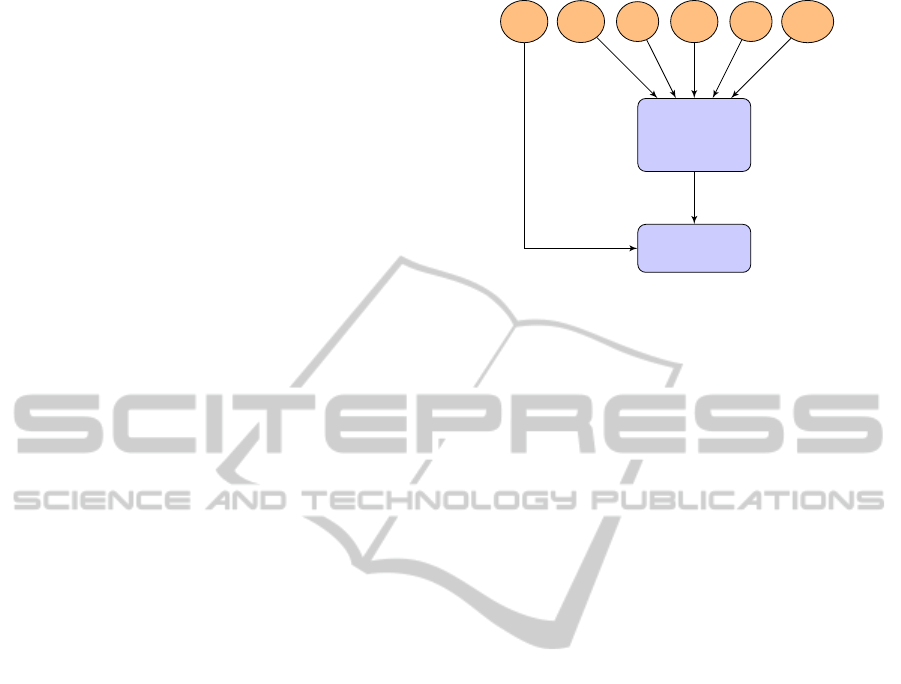
Figure 1 shows a flowchart explaining how we deter-
mine the absence of occlusion for camera C
0
. Basi-
cally, we randomly pick two other cameras and gen-
erate the visual hull from the masks of camera C
0
and
these two cameras C
a
and C
b
. The voxels defining this
visual hull are the ones who are not occluded for all
these cameras, otherwise they should be carved out of
the visual hull.
3.1.2 Occluded
One could think that no absence of occlusion means
occlusion but that would be wrong because we can
only determine occlusion in the zone where the per-
son is walking and it strongly depends on the chosen
cameras. Determining occlusion is much more com-
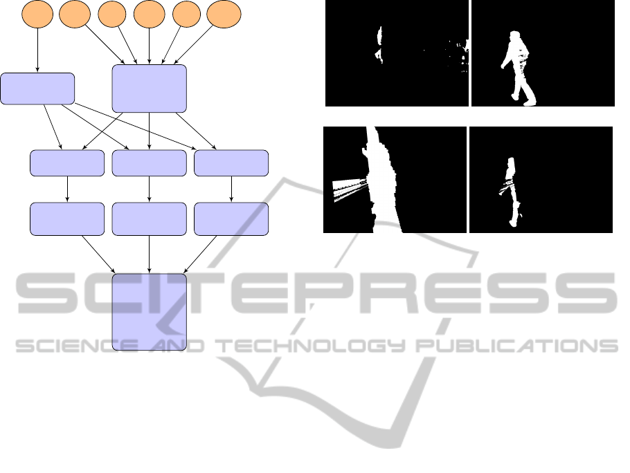
plicated. Figure 2 shows the flowchart to understand
the algorithm. We first generate the visual hull with
only the camera of which we want to determine oc-
clusion, camera C
0
. We randomly pick three cameras
and reproject the generalized cone of C
0
back on each
of the camera image planes of these cameras: C
a
, C
b
pick 2
random
cameras
C
n
...
C
1
...
C
N
generate
visual hull
C
0
C
a
,C
b
Figure 1: Flowchart to determine which voxels are not oc-
cluded for camera C
0
. Two cameras are randomly picked
from the list and we calculate the visual hull from their
masks together with the mask of camera C
0
from which we
try to determine the occlusion map. Since camera C
0
con-
tributes to the visual hull the result is a shape which is not
occluded for these cameras.
and C
c
. This reprojection results in a different mask
for each camera mask
repr,C
x
with x = a, b or c.
An example is shown in Figure 3. In Figure 3(a)
we see the mask of camera C
0
. If we look closely we
see that only half of the person is visible in this mask
which means there is occlusion. Figure 3(b) shows
the mask from another camera (mask
f gbg,C
a
) which
sees the entire person. We compare mask
f gbg,C
a
with
mask
repr,C
a
(Figure 3(c)), which is the reprojected vi-
sual hull from camera C
0
onto this other camera, ac-
cording to (FG = foreground and BG = background):
mask
occl,C
x
(x, y) = mask
repr,C
a
(x, y) = BG
∧ mask
f gbg,C
x
(x, y) = FG
(2)
The result (mask
occl,C
a
) is shown in Figure 3(d)
which indicates the invisible parts for camera C
0
in
white. The same calculations are made for the two
other randomly chosen cameras. These three masks,
in respect to the correct camera viewpoints, produce
a visual hull which consists mostly of occluded vox-
els for camera C
0
. Due to the visual hull algorithm,
we cannot guarantee that all of its voxels are really
occluded, hence the voting framework.
Notice that the self-learning occlusion algorithm
also solves another problem. Namely, when the
foreground-background segmentation continuously
fails to classify certain pixels as foreground, the votes
for occlusion will increase and the system will eventu-
ally ignore that camera for those pixels which offers a
great advantage since it would otherwise degrade the
3D model as well.
VISAPP2014-InternationalConferenceonComputerVisionTheoryandApplications
504
pick 3
random
cameras
generate
visual hull
C
n
...
C
1
...
C
N
reproject reproject reproject
determine
occlusion
determine
occlusion
determine
occlusion
generate
visual
hull with
occlusion
masks
C
0
C
a
C
b
C
c
mask
occl,C
a
mask
occl,C
b
mask
occl,C
c
mask
repr,C
a
mask
repr,C
b
mask
repr,C
c
Figure 2: Flowchart to determine occlusion for camera C
0
.
First we pick three random cameras from the list (C
1
−C
N
)
and also calculate the visual hull for C
0
only (in a bounded
area). Next, we reproject that visual hull on each of the sen-
sors of the chosen cameras. We then compare this repro-
jected mask with the original mask of the respective camera
(using formula 2). This results in occlusion masks for the
three randomly picked cameras. The visual hull generated
by these occlusion masks determines the occluded voxels
for camera C
0
in that time frame. In case of static occlusion
the complete occlusion map will be built over time.
4 QUALITY FACTOR VOTING
In a multi-camera setup not all cameras are equally
relevant to a certain voxel in space. Not only the dis-
tance to the camera, but also the angles between the
cameras (with the voxel as center) determine the rele-
vance of the information added by each camera. The
self-learning occlusion algorithm takes this into ac-
count: we add this relevance as a quality factor to
the framework. Rather than counting the number of
votes, we count these quality factors Q (0 ≤ Q ≤ 1).
The count for both cases, t
occluded
and t
visible
are kept:
t
occluded
= t
occluded
+ Q
t
visible
= t
visible
+ Q
(3)
The visual hull provides a qualitative tool for mea-
suring the relevance of a camera. For every camera we
add to the scene, the resulting 3D model is composed
by the same or less voxels, since every new camera
carves away zero or more voxels. In the next sec-
(a) mask
f gbg,C
0
(b) mask
f gbg,C
a
(c) mask
repr,C
a
(d) mask
occl,C
a
Figure 3: (3(a)) The mask of the camera C
0
for which oc-
clusion is checked. (3(b)) The mask of one of the randomly
chosen camera views C
a
(3(c)). The reprojected image of
the visual hull generated only by mask (3(a)). (3(d)) The
occluded part shown in white, which is combined with two
other cameras to calculate a visual hull and update the oc-
clusion map.
tion we investigate the influence of angle differences
between given cameras with respect to the resulting
visual hull.
4.1 Quality Factor for Two Cameras
We first consider the two-dimensional problem. In
case of two cameras we can visualize the influence
of the angle variation by keeping both cameras at the
same distance of the object. Because the overlapping
area equals infinity for small angles, we decided to re-
strict the overlapping space in a well defined circular
area. Figure 4 shows three different angles: 20
◦
, 90
◦
and 180
◦
. For an aperture angle of 20
◦
they result in
a visual hull of 2.99%, 0.75% and 4.08% respectively
of the space described by the circle through C1 and
C2, and the voxel as its center. In Figure 5 we see
the overlapping area as a function of the angle (range
from 0
◦
till 180
◦
.
We distinguish three different zones: 0 − 20
◦
,
20 − 160
◦
and 160 − 180
◦
. In the first part, the over-
lapping area is equal to infinity because the overlap-
ping area is not bounded, both cameras are looking in
the same direction from the same position. In the sec-
ond part, we find a more or less symmetrical course
with 90
◦
corresponding to the minimum overlapping
area. The third part results in a constant overlapping
area because both cameras are then facing each other.
The quality factors need to show the same trend.
Self-learningVoxel-basedMulti-cameraOcclusionMapsfor3DReconstruction
505
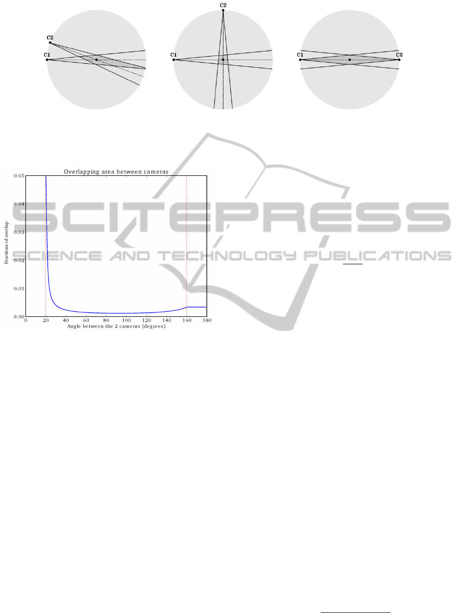
(a) (b) (c)
Figure 4: Overlapping area for an angle of 20
◦
, 90
◦
and 180
◦
between camera C1 and C2 for a certain voxel in space. We
see that the overlapping area (dark gray area) presents respectively 2.99%, 0.75% and 4.08% of the marked space (lightgray
area). We notice an angle of 90
◦
reduces the overlapping area significantly.
Figure 5: The fraction of overlap between views of two
cameras equidistant from a certain voxel, both having a
viewing angle of 20
◦
, as a function of the angle between
the cameras. The graph between 180
◦
and 360
◦
is a hori-
zontally mirrored version of this first part.
4.2 Proposed Quality Calculation or
Multiple Cameras
In case of more cameras, we determine the quality
factor of the chosen cameras with a practical ap-
proach. Since we have a fully calibrated camera
setup, we are able to determine the visual hull of vir-
tual objects with a number of cameras in this space
and because we know the virtual object, we are able
to compare the volume of the visual hull with the vol-
ume of the original object. Because voxels are cubes,
we opted for this shape. Each cube has the center of
a voxel as its own center. In order to reconstruct the
cube, the corners of the cubes are projected on each
of the image planes (equation 1). The convex hull of
these image coordinates represents the projection of
the virtual cube on the image plane. Consequently,
the visual hull of the cube is build from these projec-
tions.
From the previous section we know that the vol-
ume of the visual hull V
V H
strongly depends on po-
sition of the cameras, hence we use V
V H
to calculate
the quality factor Q. The combination of cameras that
has the smallest visual hull needs to be granted the
highest quality. Therefore we calculate the ratio of
the volume of the original cube V
cube
and the volume
of this visual hull V
V H
and use this as quality factor Q
(equation 4).
Q =
V
cube
V
V H
(4)
From the properties of a visual hull, we know that
V
V H
≥ V
cube
. Therefore Q always satisfies 0 ≤ Q ≤ 1.
The most accurate results are obtained by using the
voxels as cubes to calculate the visual hull. However,
in that case, we need subvoxel precision, which would
increase the memory usage significantly. Therefore,
we chose to use the same voxel resolution (2 cm
3
)
as the voxel resolution we use for the visual hull algo-
rithm and we use cubes with edges equal to a multiple
of the voxel resolution (e.g. 20 cm
3
).
In the pre-computation phase we calculate the
quality factors for all possible combinations of three
cameras. In case of seven cameras, that means
7
3
=
35 unique combinations for every voxel. To reduce
computation time we opt to calculate the aforemen-
tioned quality factors for an oversampled voxel space
(every 10cm in each direction). The quality factors of
the intermediary voxels are calculated from its eight
nearest neighbours in this oversampled voxel space
using weighted averaging (Figure 7). Equation 5 cal-
culates this weighted average. We define P
cube,i
as
one of the eight nearest corners from the oversampled
voxel space. The weights are equal to the euclidean
distance between such a corner point P
cube,i
and the
point P we want to calculate the interpolated quality
factor for. Q
i
represents the quality factor of the voxel
at P
cube,i
.
Q
P
=
8
∑
i=1
d(P
cube,i
, P)Q
i
8
∑
i=1
d(P
cube,i
, P)
(5)
VISAPP2014-InternationalConferenceonComputerVisionTheoryandApplications
506
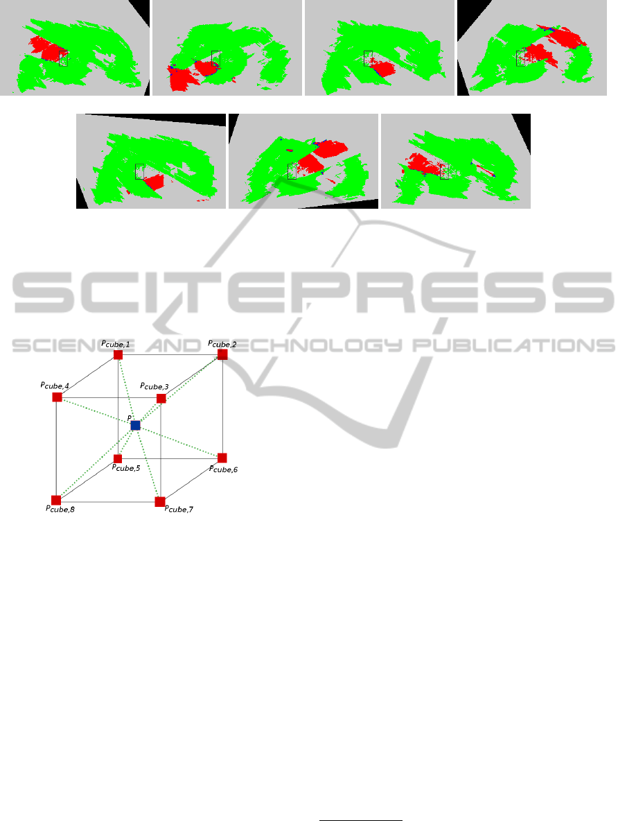
(a) (b) (c) (d)
(e) (f) (g)
Figure 6: One horizontal layer (1.20 m above ground level) of the occlusion maps of all cameras. (6(a)) bottom right corner,
(6(b)) upper right corner, (6(c)) upper left corner, (6(d)) lower left corner, (6(e)) upper left corner, (6(f)) lower left corner and
(6(g)) lower right corner. The top row shows the occlusion maps from cameras at 3.5 m from the ground, the bottom row
from the cameras 1.2 m from the ground. The black rectangle represents the occlusion object. We distinguish five classes:
occluded (red), non-occluded (green), undecided (blue), unknown (gray) and out of sight (black). Errors in the occlusion map
are due to noise in the foreground-background images.
Figure 7: Interpolation of intermediary voxels. Red filled
squares represent voxels from the oversampled voxel space
while the blue squares inside the cube represents a voxel
from the normal voxel space. Green dashed lines represent
the distance from the center of the voxel P to one of the
cube corner voxels.
5 RESULTS
5.1 Test Setup
We made a test setup of 8m×4m×3.5m (w × l × h)
with seven cameras, four of them placed in the top
four corners and three others about 1.2 m from the
ground on the vertical edges. In the middle of the
room we placed an occluding object (Figure 8). All
cameras have 780 × 580 px image resolution. We cal-
ibrated all cameras intrinsically and extrinsically. In
the next phase we asked a person to walk through the
room. The aim is to visit each voxel near occluding
objects at least once. However, the more often the per-
son visits a certain voxel, the more certain the system
becomes about occlusion or no-occlusion at that cer-
tain voxel. Because we only take into account static
occlusion for the moment, we can run the occlusion
detection once and use the results later on. In case
of random camera combinations, we need to compute
three visual hulls per camera per frame, hence 21 vi-
sual hulls (with seven cameras). This roughly results
in 0.5 frames per second.
5.2 Classification
In Figure 6 we see the results of the algorithm.
1
The visited voxels have been classified into five
classes: occluded (red), non-occluded (green), unde-
cided (blue), unknown (gray) and out of sight (black).
The voxels are classified by the votes t
occluded
, t
visible
and whether the voxel is visible by the camera:
Class =
occluded if t
occluded
> t
visible
non-occluded if t
occluded
< t
visible
undecided if t
occluded
= t
visible
unknown if t
occluded
= t
visible
= 0
out of sight if voxel not in field of view
(6)
Note that in the final occlusion map we assume
undecided and out of sight as occluded and un-
known as non-occluded and hence distinguish only
two classes: occluded and non-occluded.
1
More results of the occlusion maps of these se-
quences can be found at http://telin.ugent.be/∼mslembro/
?q=node/14
Self-learningVoxel-basedMulti-cameraOcclusionMapsfor3DReconstruction
507
(a) (b)
(c) (d)
(e) (f)
(g)
(h) Damaged
3D model due to
ignoring occlusion
(i) State of the art (j) Recognizable 3D
model thanks to oc-
clusion maps
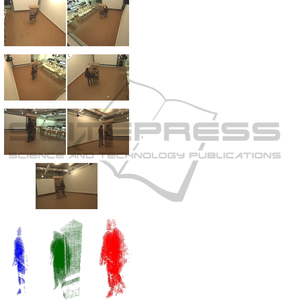
Figure 8: 8(a)) - (8(g)) Input images of all camera views. In
(8(h)) we ignore the occlusion information leading to an in-
correct 3D shape. () shows the state of the art method where
we see a lot of extra voxels which should not belong to the
3D model. In (8(j)) on the other hand we still recognise a
person in the 3D model because the cameras responsible for
degrading the 3D shape are ignored.
5.3 Visual Hull Results
Using the generated occlusion maps we are now able
to reconstruct a person, walking trough the room,
without losing occluded parts. The occlusion maps of
all cameras are evaluated to determine for each voxel
separately which cameras are relevant to build the 3D
model. Only cameras classified as non-occluded for
a voxel are taken into account. In Figure 8 we see
the visual hull constructed with and without occlusion
mapping. The 3D model of the person is significantly
more recognizable in Figure 8(j) which takes the oc-
clusion into account.
6 CONCLUSIONS
In this paper we presented a self-learning occlusion
map algorithm derived from the voxel perspective to
improve the 3D reconstruction of an object in a scene
with static occlusion. The method is based on the vi-
sual hull concept and builds a separate occlusion map
for each camera. We designed a voting framework in
order to classify voxels as occluded or non-occluded.
We showed promising results from our test setup with
seven cameras and one occluding object.
7 FUTURE WORK
As a first step we chose to only allow purely static
occlusion. It is however also possible to have objects
which are moved around in the scene e.g. chairs. The
occlusion maps could be continuously updated in a
parallel process. We could also estimate the shape of
the occluding objects in the scene. If the camera po-
sitions and orientations are then changed. New occlu-
sion maps could be automatically generated from the
old ones without having to run the occlusion detection
again.
REFERENCES
Apostoloff, N. and Fitzgibbon, A. (2005). Learning spa-
tiotemporal t-junctions for occlusion detection. In
Computer Vision and Pattern Recognition, 2005.
CVPR 2005. IEEE Computer Society Conference on,
volume 2, pages 553–559. IEEE.
Brostow, G. J. and Essa, I. A. (1999). Motion based de-
compositing of video. In Computer Vision, 1999. The
Proceedings of the Seventh IEEE International Con-
ference on, volume 1, pages 8–13. IEEE.
VISAPP2014-InternationalConferenceonComputerVisionTheoryandApplications
508

Corazza, S., M
¨
undermann, L., Chaudhari, A., Demattio,
T., Cobelli, C., and Andriacchi, T. (2006). A mark-
erless motion capture system to study musculoskele-
tal biomechanics: Visual hull and simulated anneal-
ing approach. Annals of Biomedical Engineering,
34(6):1019–1029.
Corazza, S., M
¨
undermann, L., Gambaretto, E., Ferrigno,
G., and Andriacchi, T. P. (2010). Markerless motion
capture through visual hull, articulated icp and sub-
ject specific model generation. International journal
of computer vision, 87(1-2):156–169.
Favaro, P., Duci, A., Ma, Y., and Soatto, S. (2003). On
exploiting occlusions in multiple-view geometry. In
Computer Vision, 2003. Proceedings. Ninth IEEE In-
ternational Conference on, pages 479–486. IEEE.
Grauman, K., Shakhnarovich, G., and Darrell, T. (2003). A
bayesian approach to image-based visual hull recon-
struction. In Computer Vision and Pattern Recogni-
tion, 2003. Proceedings. 2003 IEEE Computer Society
Conference on, volume 1, pages I–187. IEEE.
Guan, L., Sinha, S., Franco, J.-S., and Pollefeys, M. (2006).
Visual hull construction in the presence of partial
occlusion. In 3D Data Processing, Visualization,
and Transmission, Third International Symposium on,
pages 413–420. IEEE.
Kim, H., Sakamoto, R., Kitahara, I., Toriyama, T., and
Kogure, K. (2006). Robust foreground segmentation
from color video sequences using background sub-
traction with multiple thresholds. Proc. KJPR, pages
188–193.
Laurentini, A. (1994). The visual hull concept for
silhouette-based image understanding. Pattern Anal-
ysis and Machine Intelligence, IEEE Transactions on,
16(2):150–162.
Zivkovic, Z. (2004). Improved adaptive gaussian mixture
model for background subtraction. In Pattern Recog-
nition, 2004. ICPR 2004. Proceedings of the 17th In-
ternational Conference on, volume 2, pages 28–31
Vol.2.
Self-learningVoxel-basedMulti-cameraOcclusionMapsfor3DReconstruction
509
