
Virtual Touch Screen “VIRTOS”
Implementing Virtual Touch Buttons and Virtual Sliders
using a Projector and Camera
Takashi Homma and Katsuto Nakajima
Department of Information Systems and Multimedia Design, Tokyo Denki University, Tokyo, Japan
Keywords: Projector-camera Systems, Projector-based Display, Touch Detection, Virtual Touch Screen.
Abstract: We propose a large interactive display with virtual touch buttons and sliders on a pale-colored flat wall. Our
easy-to-install system consists of a front projector and a single commodity camera. A button touch is
detected based on the area of the shadow cast by the user’s hand; this shadow becomes very small when the
button is touched. The shadow area is segmented by a brief change of the button to a different color when a
large foreground (i.e., the hand and its shadow) covers the button region. Therefore, no time consuming
operations, such as morphing or shape analysis, are required. Background subtraction is used to extract the
foreground region. The reference image for the background is continuously adjusted to match the ambient
light. Our virtual slider is based on this touch-button mechanism. When tested, our scheme proved robust to
differences in illumination. The response time for touch detection was about 150 ms. Our virtual slider has a
quick response and proved suitable as a controller for a Breakout-style game.
1 INTRODUCTION
As consumer-grade digital projectors and cameras
have become less expensive, many interactive
projector-camera systems have been proposed. In
particular, since ordinary flat walls can be used as
the screen, large interactive displays can be used for
digital signage and information boards in public
spaces without the need for expensive touch panels.
There are two types of user interaction under a
projector-lighted environment. One is gesture based
(primarily hand gestures) (Licsar, 2004; Sato, 2004;
Winkler, 2007; Lech, 2010; Fujiwara, 2011; Shah,
2011), and the other is touchscreen based (Kjeldsen,
2002; Pinhanez, 2003; Borkowski, 2004; Borkowski
2006; Kale, 2010; Wilson, 2005; Song, 2007; Kim,
2010; Park, 2010; Audet, 2012; Dai, 2012). For a
gesture interface, users must learn the gestures
corresponding to defined functions and may need
training. On the other hand, touching the screen is
intuitive and increasingly popular due to the recent
spread of touch-based devices such as smartphones.
Various methods for touch detection on a
projector-lighted screen have been proposed. The
methods described in the next section include (a)
measuring the position and distance of the
hand/finger from the screen by using multiple
cameras or depth sensors such as the one used in
Microsoft Kinect (Microsoft, 2010), (b) observing
size changes in the shadow cast by a hand/finger
approaching the screen (Pinhanez, 2003; Kale, 2010;
Wilson, 2005; Song, 2007), and (c) tracing the tip of
the hand/finger until the tip stops on some
predefined touch area (Kjeldsen et al., 2002;
Borkowski, 2004; Borkowski 2006; Audet, 2012).
Our aim is to make large, easy-to-install,
economical interactive displays; therefore, we use a
front projector and a nearby camera. A hand touch
on the screen is detected by the area of the shadow
cast by the user’s hand. The key idea is that the
shadow color does not depend on the projected color.
The issue is when and how to alter the button color
to capitalize on this idea without sacrificing usability.
Our virtual touchscreen system, called VIRTOS,
is designed to function in a space where ambient
light conditions may change. VIRTOS continually
monitors the touch area (the "button" or "touch
button"), and when a large foreground (non-
background, a hand or its shadow) covers and stops
on the button, the color of the projected touch button
is altered briefly in order to distinguish the shadow
from the hand. If the shadow area, the color of
which is not changed, is very small, then the system
34
Homma T. and Nakajima K..
Virtual Touch Screen “VIRTOS” - Implementing Virtual Touch Buttons and Virtual Sliders using a Projector and Camera.
DOI: 10.5220/0004728600340043
In Proceedings of the 9th International Conference on Computer Vision Theory and Applications (VISAPP-2014), pages 34-43
ISBN: 978-989-758-009-3
Copyright
c
2014 SCITEPRESS (Science and Technology Publications, Lda.)

recognizes this as a touch. VIRTOS also supports a
slider (scrollbar) based on this virtual touch-button
mechanism.
The background subtraction technique is used to
segment the foreground. The reference image for
each button, used for background subtraction, is
continuously updated to account for changes in
ambient light.
We tested the accuracy and response time of our
virtual touch button and slider.
To demonstrate the usability of VIRTOS, we
also developed two applications: one is for slide
presentations, with two virtual buttons to navigate
the slides, and the other is an action game controlled
by the virtual slider.
In Section 2, various alternate methods for touch
detection are discussed, and Section 3 describes the
implementation of VIRTOS. Section 4 presents the
evaluation results, and two applications of VIRTOS
are shown in Section 5. We conclude with Section 6.
2 TOUCH DETECTION
This section summarizes various methods to detect a
touch of a hand or finger on the screen. We focus on
virtual touch buttons on the screen, indicated by a
specific projected color, because touch buttons are a
general and fundamental widget for touch interfaces.
2.1 Distance and Location
Measurement by Two Cameras
or a Depth Sensor
Probably the most straightforward method to locate
the position of a hand or finger on the x and y axes
of the screen uses two cameras. This method, in
addition to requiring two (or more) cameras,
requires that cameras be installed along the
top/bottom and left/right sides of the screen, and this
restricts the flexibility of the installation. To provide
flexibility of installation, we aim to require only one
camera and impose minimal restrictions on its
placement.
Depth sensors, such as the one used in Microsoft
Kinect (Microsoft, 2010), may be able to measure
the distance between the hand/finger and the screen
if the sensor is carefully positioned in relation to the
screen surface. However, these sensors are still more
expensive than commodity web cameras.
2.2 Hand or Finger Segmentation
and Tracking
If it is possible to locate the position of a hand/finger
and extract its shape by a single web camera,
configuration of the system becomes simple.
However, because the color of the hand or finger is
overwhelmed by the projector’s light, skin color
extraction based on hue value does not work in most
cases (Kale, 2004). In addition, the shadow of the
hand/finger is cast on the screen due to the
perspective difference between the projector and the
camera and disrupts analysis of the hand/finger
shape.
Background subtraction is an effective and
frequently used method for extracting the
foreground region, even in the projector illumination.
The following are three types of reference images
that can be subtracted from the camera input image
and the method to do so.
(1) Real background: by memorizing an image of
the screen where a virtual button image is
projected.
(2) Dynamically estimated background: by
estimating background pixel values at each pixel
position based on the several latest input frames
(Brutzer, 2011; Winkler, 2007).
(3) Synthesized background: by predicting the color
of each pixel from the mapping relation derived
by comparing the projected colors and reference
samples taken by the camera during system
initialization (Hilario, 2004; Licsar, 2010; Kale,
2004; Audet, 2012; Dai, 2012).
Method (1) is simple and fast but must be altered
due to changes in ambient light. Method (2) often
requires heavy computation for accurate estimation
(Brutzer, 2011) and forces a trade-off between
response time and accuracy of foreground extraction.
In theory, method (3) enables the real-time
production of any background with arbitrary colors
and images. However, mapping all of the colors
necessitates a large look-up table, which must be
constructed in a complex initialization. Furthermore,
it is difficult to adapt to ambient light changes
without reconstructing the look-up table.
Another way to extract the foreground region
without affecting the projected light is to use
infrared light and a camera with an infra-red filter. It
is easy to extract the foreground from infrared
images (Sato, 2004; Wilson, 2005). However,
infrared devices are costly.
All the methods described above extract both a
hand/finger and its shadow, and they should be
VirtualTouchScreen"VIRTOS"-ImplementingVirtualTouchButtonsandVirtualSlidersusingaProjectorandCamera
35

sensitive enough for precise touch detection. The
hand/finger can be separated from its shadow by the
intensity value. If the intensity of a pixel in the
foreground is lower than some threshold, the pixel is
regarded as a part of the shadow. The threshold
value must account for the level of ambient light
around the system, and doing so is not an easy task.
For environments in which shadow segmentation
cannot be done with sufficient accuracy, there are
several methods to detect a touch by tracking the
movement of the hand/finger (Kjeldsen et al., 2002;
Borkowski, 2004; Borkowski 2006; Audet, 2012).
In Audet (2012), the tip of the finger is tracked.
If it enters a button region and stops, the system
detects a touch. For real-time processing, the system
utilizes simple technologies such as frame
differences for moving-object tracking and a simple
template matching for locating the tip of the finger.
If more than one tip is recognized, the most distant
tip from the user’s body is selected for touch
detection. In Borkowski (2004) and Borkowski
(2006), an elongated foreground (i.e. a finger) is
detected in the button region by monitoring changes
in the region’s luminance. The button region is
virtually split into two or more subregions, one
fingertip-sized subregion is located in the center of
the button region, and the other subregions surround
this central subregion. A touch by a finger tip on the
center of the button is detected when luminance
changes are observed at only some of the subregions
and at the central subregion.
These methods can efficiently recognize an
elongated foreground shape, but it is difficult for the
system to distinguish a finger touching the button
from a hovering finger or the elongated shadow of
something else. Therefore, such methods may be
suitable for a small personal display, but they are
problematic for a large interactive display with
hand-sized large buttons.
2.3 Touch Detection by Shadow
One of the characteristics of a projector-based
system is that a shadow unavoidably appears when a
user is touching or about to touch the screen,
because the hand intercepts the projected light; the
camera, owing to its perspective different from that
of the projector, sees this shadow. This particular
feature can be utilized for detecting a touch.
If a front camera can reliably distinguish
between a hand and its shadow, a screen touch can
be detected by calculating the relative proportions of
the hand and the shadow in the camera image (Kale,
2004; Song, 2007). When a hand is about to touch
the screen but still hovering on it, the shadow is
relatively larger than when the hand is touching.
This method depends on accurate separation of the
shadow from the hand through the use of only
optical color information.
The shadow color might be recognized more
easily than the hand color because it is not affected
by the projected light and is almost the same as the
unilluminated screen color. The intensity
(brightness) value is often used as a threshold
criterion (Brutzer, 2011; Winkler, 2007). The pixels
with lower intensity value than this threshold are
extracted as shadow. However, this simple criterion
may falsely accept more than a few non-shadow
pixels, and the threshold must be adjusted whenever
the ambient light changes.
In Wilson (2005) and Kim (2010), the shape of
the finger shadow is the metric for touch detection.
To generate a clean shape, some morphological
operations must be performed before analysis of the
shadow shape.
2.4 Proposed Method – Measuring
Shadow Area
As stated in Section 1, our target system is a large
interactive display. Virtual touch buttons are as large
as a hand and are supposed to be touched with the
whole hand. Therefore, we do not rely on the shape
and direction of the user’s hand for touch detection.
To ensure real-time performance, we try to avoid
time-consuming operations, such as morphological
ones and shape analysis. Therefore, we use an area
proportion metric in the button region.
The shadow color on the screen can be known in
the system by taking an image with the projector off
during initialization. However, ambient light may
change throughout day.
One way to know the shadow area in the touch
detection process is to intercept the projected light.
So, by altering the color of projected light in the
button area, we can find those pixels that do not
change color after the projected light changes. As
both the button region without interception and the
touching hand are affected by the color change, this
scheme works out except when the user wears a
black or very dark glove (Figure 1). Thus, under the
following two conditions, we can achieve touch
detection even in places where the ambient light
changes.
(a) The proportion of the foreground (non-
background) area exceeds a threshold.
(b) The proportion of shadow is below a separate
threshold.
VISAPP2014-InternationalConferenceonComputerVisionTheoryandApplications
36
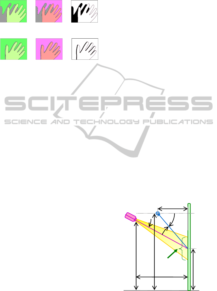
(a) When hovering: if the button color is changed (from
left to center), the shadow area (black area, right) is
shown to be large.
(b) When touching: if the button color is changed (from
left to center), the shadowed area (black area, right) is
shown to be very small.
Figure 1: Touch Detection by Shadow Area.
For condition (a), we utilize background subtraction
to extract the foreground. The image of the color
button without any object on it is acquired by the
camera as a reference image during system
initialization and updated continuously. The details
are described in the next section.
One of the important issues in our scheme is
when and how the button color is changed. Another
issue is usability. We think that a brief color change
of the button may be perceived by users as a
response to a button touch. Thus, when a large
proportion of the button region is covered by a
foreground, we alter the button color for the
minimum duration required for the camera to sense
the change.
Because this scheme does not depend on the
shape of touching object (such as the hand), it is not
possible to recognize whether more than one hand is
simultaneously touching. However, we believe that
this is a reasonable limitation for a large interactive
display. In addition, simultaneous touch can be
reduced by limiting the size of the button, for
example, to palm sized.
Based on the discussion above, we designed and
implemented a large display with virtual touch
buttons. We also developed a slider (scrollbar) based
on our touch-button mechanism. The next section
describes the details of the implementation of our
touchscreen, which we have named VIRTOS.
3 VIRTUAL TOUCH SCREEN
“VIRTOS”
3.1 Installation
Our touchscreen requires a projector, a commodity
optical camera, a computer connected to these
devices, and a screen or a pale-colored flat wall.
These devices are easily installed. The projector and
the camera must be arranged in front of the screen,
but there are few restrictions on their positions; the
projector should be able to project the content onto
the screen clearly, and the camera should be able to
observe the content. It is also necessary to place the
camera obliquely from the projector (i.e., off-axis)
so that the camera can observe shadows of the hand
touching the screen.
Preferably, the projector is placed as high as
possible so that the projected content can be
observed on the screen with minimal blocking of
projected light by the user (or users) standing in
front of the screen.
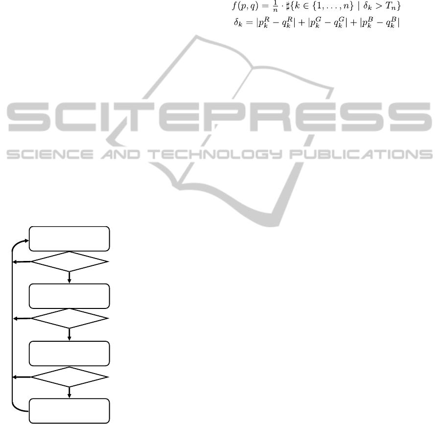
Figure 2 shows a typical installation of VIRTOS.
The projector is placed on the vertical center line in
front of the screen. The camera may be placed at a
slant, for example, 50 cm left or right of the center
of the screen.
3.2 Initialization
Our touchscreen is automatically initialized when
the system is invoked. First, the relationship between
the projector and the camera is calibrated to let the
system know the button positions. This task is done
by having the camera view a projected chessboard
pattern (Zhang, 2000).
The second step of initialization is to acquire
virtual button images. VIRTOS can have more than
one touch button, each of a different color. The
projector projects the various buttons to their
positions on the screen, and the system memorizes
each “button-only” (i.e., without foreground) image
from the camera input. These images are used as the
Screen
Camera
18.5°
38.5°
20°
Projector
210
(cm)
78
120
Projection
area
188
148
Figure 2: Typical Installation of VIRTOS.
VirtualTouchScreen"VIRTOS"-ImplementingVirtualTouchButtonsandVirtualSlidersusingaProjectorandCamera
37
reference image for the background subtraction in
the touch detection process described below.
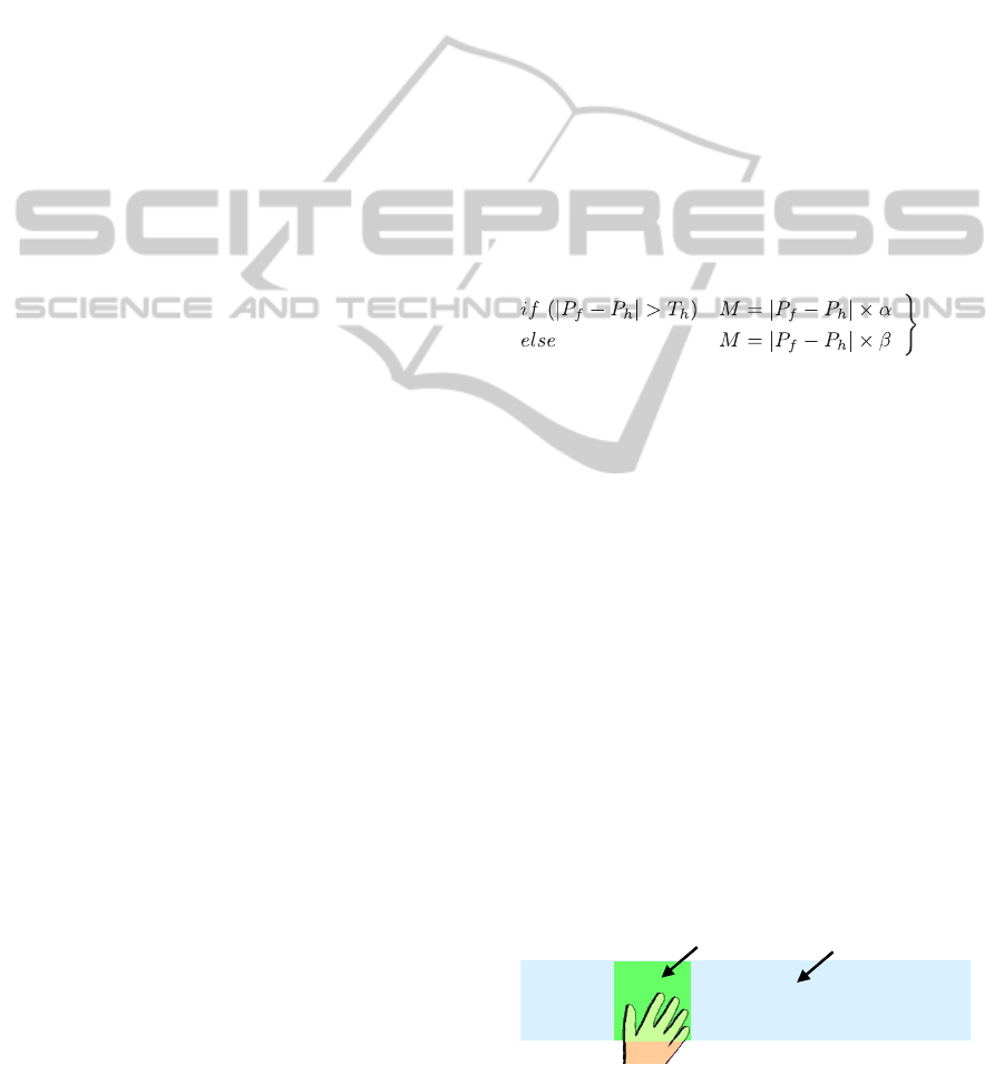
3.3 Touch Detection
Each button has one of the following states in the
touch detection process. Figure 3 shows the state
transition between these states.
(1) Normal: The button is currently not touched,
and nothing is covering the button.
(2) Waiting: Something is covering the button, and
the process is waiting for the object (hand) to stop.
(3) Checking: The process is checking whether the
object is touching the button. During this state, the
button color is briefly changed to a different color.
(4) Touching: The button is being touched. The
process is waiting for the touching object to leave
the button.
All buttons start in the Normal state. These states
are sequential and can be regarded as filters for the
touch detection. For example, the state subsequent to
the Normal state is always the Waiting state. If
each procedure for a state (except for the Normal
state) finds that the condition is not met to proceed
to the next state, the button state will be changed
immediately to the Normal state. The details of each
state are as follows.
Waiting
Large foreground ?
Foreground moving ?
Large shadow ?
Normal
Checking
Touching
Yes
No
Yes
No
No
Yes
Updatebuttonimage
continuously
Temporarilychange
buttoncolor
Sendtoucheventto
applicationand
waitforforegroundto
disappear
Donotproceed
ifforegroundismoving
Figure 3: Flowchart of State Transitions.
3.3.1 Normal State
The Normal state means that the button is not being
touched and nothing is covering the button. During
this state, the number of pixels within the button
area that differ between the current camera image
and the reference “button-only” image is calculated
at every frame. If the amount of difference is larger
than a predefined threshold (e.g., 25%), the system
decides that something is covering the button, and
the button state is changed to the Waiting state. The
difference between two images is calculated by
equations (1) and (2).
(1)
(2)
where p and q are the images being compared and n
is the number of pixels in the images. δ
k
is the
distance in RGB color space from the pixel at the
position k in p to the pixel at the corresponding
position in q. Tn is a threshold (e.g., 70) to
determine the pixels differ from each other. P
i
k
and
q
i
k
denote the value of the i-color channel {i
∈
R,G,B}
at the position k. The value is normalized to
range [0,1), and therefore the result of the function f
is also in [0,1). Smaller values represent smaller
differences and vice versa. The function f is also
used in subsequent processes.
We chose to use the Manhattan distance
(equation (2)) instead of the Euclidean distance for
the sake of calculation speed. However, this choice
is not intrinsic to system functioning.
The button-only images are first acquired in the
initialization. A problem with this is that the button
colors in the camera image may vary with changes
in the ambient lighting condition, such as light
through windows. This makes it difficult to precisely
extract the foreground in background subtraction. To
deal with this problem, VIRTOS updates the button-
only images continuously when no foreground
objects are observed in the button region during the
Normal state. The values of the pixels of the button-
only image are updated incrementally. They are
increased or decreased by one in the range from 0 to
256 if the currently observed pixel value differs
from the current reference image.
3.3.2 Waiting State
The process during the Waiting state is just to wait
for the object (foreground) to stop moving. This step
is required to avoid erroneous detection in the
subsequent process.
To determine whether the object is moving, the
current camera frame is compared with the previous
frame. If the difference (the number of different
pixels) is smaller than a predefined threshold for
some duration (e.g., 25% for 100 ms), the button
VISAPP2014-InternationalConferenceonComputerVisionTheoryandApplications
38
state is changed to the Checking state. Otherwise,
the process waits until the measure difference drops
below the threshold.
During this state, the area of the foreground is
also calculated at each frame. If the foreground area
becomes smaller than a threshold (e.g., 25%), the
button state is changed to the Normal because the
object is regarded as having moved away from the
button.
3.3.3 Checking State
When the button state is changed to the Checking
state, the current camera image is saved. Then, the
button color is changed to another pre-defined color
that is sufficiently different from the original button
color (e.g., green to magenta).
By changing the color, it is possible to determine
the shadow area. The difference between the saved
image and the current image within the button area
is the criteria for a touch. If the object is actually
touching the button, the difference will be quite
large, almost the whole the button area, because the
background area is also included in the difference. If
the object is not touching and is instead hovering on
the button, the difference is less by some amount
than the button area because of the shadow cast by
the object.
If a large shadow, such as a shadow of the user’s
head or body, covers the button and does not move
for a while, the button state proceeds to this state.
However, our color change mechanism eliminates
false touch detection because the difference between
the saved image and the current image will be very
small.
The threshold for the area of shadow to
determine a touch depends on the installation
geometry, the size and position of the touch button
and the user’s method of touch. In our experiment,
8% was an appropriate threshold for an 8 to 12 cm
button when the projector and the camera were
placed as shown in Figure 2.
If the process determines that the button is being
touched, the button state is changed to the
subsequent Touching state. Otherwise, the button
state will return to the Normal state. In either case,
the button color is reverted to the original color.
The altered color should be maintained until the
system captures the image after the color change.
The calculation of the difference is very quick.
Therefore, the delay time from the command to
change the color of projection to the camera input is
dominant in the Checking state. This gives a
response time of around 150 ms.
3.3.4 Touching State
During this state, the process waits for the touching
object to leave the button by monitoring the amount
of foreground. When the object leaves the button,
the button state is changed to the Normal state.
If desired, a “long press” function can easily be
supported by measuring the time in the Touching
state.
3.4 Slider (Scrollbar)
Our touch slider is implemented as an extension of a
VIRTOS touch button.
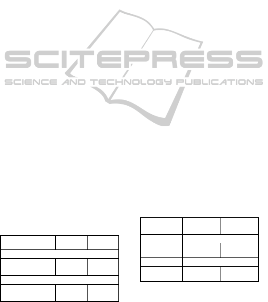
The sliding zone and the slider handle (scrollbar)
are defined and projected in different colors (Figure
4). In the Touching state, when the centroid of the
foreground (hand) is different from the centroid of
the slider handle, the handle position is moved
toward the foreground position. To generate smooth
movement, the handle position is moved as follows:
(3)
where P
f and Ph are the centroids of the foreground
and of the slider handle, respectively. M is the
amount of the move toward the foreground. The
parameters α (<1) and β (<α) act to damp movement
to prevent overshooting and vibration. The threshold
T
h chooses between α and β according to the
distance between the current handle position and the
foreground object. Each of α, β, and T
h should be
set in accordance with the size of the slider zone and
the handle.
Foreground segmentation is performed based on
the background subtraction. Two background
images are used: one is the zone image without the
slider handle, and the other is the zone image filled
with the color of the slider handle. The foreground
region is extracted from the input image as the pixels
having a color different from both the zone color and
the handle color.
The system updates the image of the sliding zone
and the slider handle in the Normal state and
recreates the two background images.
Slider handle Slider zoneSlider handle Slider zone
Figure 4: Slider Zone and Slider Handle.
VirtualTouchScreen"VIRTOS"-ImplementingVirtualTouchButtonsandVirtualSlidersusingaProjectorandCamera
39

3.5 Software Implementation
VIRTOS is provided as a class library based on
the .NET Framework 4.5 so that our virtual touch
buttons and virtual sliders are easily embedded in
applications. VIRTOS is implemented in C# and
XAML for Windows Presentation Foundation
(WPF) and partly in C++/CLI for OpenCV2.3.1.
4 EXPERIMENTATION
AND EVALUATION
The major challenges to VIRTOS in providing a
way to interact with practical large-screen
applications are stability under ambient light
changes, interactive response time, and functionality.
We conducted three experiments to evaluate our
touch button and touch slider system: (1)
measurement of the accuracy of the shadow
segmentation by our method, (2) a test of the touch
detection rate, and (3) a test of slider responsiveness.
The spatial arrangement of the devices in the
experiments was the same as shown in Figure 2. A
whiteboard was used as a screen. A projector (Epson
EB-X12) capable of up to 2,800 lm and a
commodity camera (Sony PlayStationEye) were
connected to a 3.1 GHz Windows PC (Intel Core i5-
2400) with 8 GB of memory.
4.1 Shadow Segmentation
One of the key ideas for our virtual touch detection
is a method to detect shadow pixels in the button
area.
Table 1 shows the precision, recall and F-
measure for the results of shadow segmentation by
our method (a), in which the button color is briefly
altered. The button color was green
(R=0,G=255,B=0), and the alternate color for touch
detection was magenta (R=255,G=0,B=255).
Measurement was performed under two ambient
light conditions, 620 lx (bright) and 12 lx (dim).
Two test image pairs of a hand and its shadow on a
touch button region illuminated by green and
magenta were used. The ground truth of the shadow
for each condition was established by thresholding
the green-illuminated test image itself with a
manually optimized threshold for brightness. One
was optimized under the bright environment (620 lx),
and the other was optimized under the dim one (12
lx).
The precision is the ratio of the correctly
extracted shadow pixels to all the extracted pixels as
shadow, and the recall is the ratio of the correctly
extracted shadow pixels to all the true shadow pixels.
The F-measure is the harmonic mean of precision
and recall.
Table 1 also shows the results for simple
thresholding methods: in (b), pixels whose
brightness were under a threshold manually
optimized for the bright environment were extracted;
in (c), pixels were extracted as in (b) except that the
threshold that was optimized for the dim
environment.
The result shows our method can accurately
extract the shadow pixels and is robust to changes in
ambient light.
4.2 User Test for Touch Button
Even if shadow segmentation is successful, touch
detection faces another difficulty. The area of the
shadow depends on the shape of the user’s hand and
its elevation angle from the screen. To evaluate the
usability of our touch button, we conducted a user
test using the same installation as in Figure 2. The
button color and the altered color were the same as
in 4.1.
Five men participated in this test. Each
participant was asked to touch the button 20 times
with his bare hand in arbitrary ways in terms of hand
shape, depth to the button area, and hand elevation
angle. They were not asked to pay attention to
whether the system detected the touch or reacted.
This test was repeated four times for each
participant: once for each pairing of an ambient light
condition, about 690 lx or 12 lx on the screen when
the projector was off, and button size, 85 mm square
or 120 mm square.
Table 1: Shadow Segmentation.
Shadow
segmentation
(%)
Bright
( 620 lx )
Dim
( 12 lx )
Prec. Recall
F-
measure
Prec. Recall
F-
measur
e
(a) Proposed
(button color change)
81 83 82 73 69 71
(b) Low brightness
(optimized for
bright)
(100) (100) (100) 56 100 72
(c) Low brightness
(optimized for dim)
100 63 77 (100) (100) (100)
Table 2 shows reasons for failure along with
their rates. The following reasons were found: (a)
hand movement was too fast to change the color of
the touch button; (b) incorrect estimation of the
VISAPP2014-InternationalConferenceonComputerVisionTheoryandApplications
40
shadow area when comparing the color-changed
image to the reference image.
Result (a) shows that users need some
notification from the system or they tend to move
their hand too quickly. Result (b) indicates that our
touch detection method works accurately and is
robust to illumination changes.
Although the change of the button color is
perceived by the user, we confirmed in this test that
most users are not annoyed by it because they
recognize this change as the system’s reaction to
touch.
When the user is not touching the interface, color
changes should be reduced as much as possible. For
this purpose, VIRTOS was designed to initiate a
color change only when both some amount of
foreground (e.g., more than 25%) is observed the
foreground object stops in the button.
The time from the user’s touch on the screen to a
visible system action, such as projecting a picture,
was about 150 ms.
4.3 User Test for Touch Slider
If a slider (scrollbar) does not smoothly follow the
movement of the user’s hand, it will be annoying
and stressful to use.
In this test, the participant was asked to
repeatedly move the slider handle to target positions
chosen randomly by the system. The average time to
move between positions was evaluated. The
installation was the same as in the Figure 2. The
color of the handle and the altered color were the
same as in 4.1, and the color of the slider zone was
light blue (R=178, G=203, B=228).
Five participants (5 men) were asked to move
the slider handle left or right 20 times in a trial. The
test system indicated a target position and displayed
it until the participant successfully moved the handle
to that position and stopped. Immediately after the
handle stopped at the target position, the system
showed the next one. The slider zone was divided
Table 2: Button Touch Detection.
Reason for
failure (%)
Bright
( 690 lx )
Dim
( 12 lx )
Button size = 85 mm sq.
(a) Too fast to change 9.0 2.0
(b) Detection failure 0.0 6.0
Button size = 120 mm sq.
(a) Too fast to change 3.0 4.0
(b) Detection failure 0.0 19.0
into 10 target positions, and the test system
randomly selected one of these positions as the next
target. The total time to complete 20 moves was
measured for each trial. Each participant completed
four trials: two in bright light and two in dim light.
Table 3 shows the average time of each handle
move for all participants. The results in the second
trial are about 0.5% to 8% better than the results of
the first trial because participants improved their
manipulation of the slider from the first trial.
We expect that the response times (manipulation
times) in Table 3 are good enough for digital signage
and direction boards. As discussed in the next
section, our virtual touch slider is suitable even as a
control handle for action games if very quick
movements are not required.
5 APPLICATION
Virtual touch screens are especially useful for large
display applications in public spaces, such as
interactive direction boards and digital signage,
because they are less expensive and less prone to
breakdown than large touch panels.
We developed two applications to demonstrate
the usability of VIRTOS. The first application uses
two VIRTOS touch buttons to control forward and
backward movement through a slide presentation
(Figure 5 (a)). The lower touch button in Figure 5
advances a slide; the upper button goes back a slide.
During a full-day demonstration in a bright room,
the touch buttons of this application were stable and
quick enough for presentation navigation.
The other application is a Breakout-style game in
which a VIRTOS touch slider is used to control the
game bar (Figure 5 (b)). The touch slider acts as a
handle for the game bar; it deflects a puck to break
the blocks in the upper area of the game screen.
Table 3: Touch Slider Response.
Touch slider
response
Bright
( ≈ 700 lx )
Dim
( ≈ 16 lx )
First trial Time to move (sec)
(a) Handle size
= 85 mm sq.
1.82 2.00
Second trial Time to move (sec)
(b) Handle size
= 85 mm sq.
1.68 1.99
During a half-day demonstration of the game to
about 50 users, there were no questions about color
VirtualTouchScreen"VIRTOS"-ImplementingVirtualTouchButtonsandVirtualSlidersusingaProjectorandCamera
41
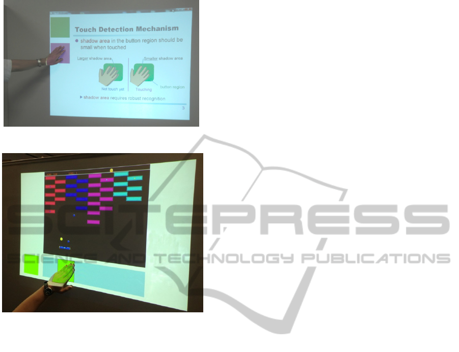
(a) Slide presentation on a wall with two virtual touch
buttons (upper left green and violet).
(b) Breakout game with a virtual slider (right) and a virtual
touch button (left) on a white board
Figure 5: VIRTOS Applications.
changes of the button. We assume that these users
also perceived the change as a reaction to the touch,
as in 4.1. We also found that our current touch slider
was moderately usable for this action game.
However, when players wanted to move the game
bar quickly (so as not to loose the puck), they
occasionally moved their hand so fast that the slider
failed to follow. Therefore, we should improve the
response of the touch slider for this kind of game.
6 CONCLUSIONS
We proposed a large interactive display named
VIRTOS, with virtual touch buttons and touch
sliders, which consists of a projector, a pale-colored
wall, a computer, and one commodity camera as a
highly practical and useful projector-camera system.
In VIRTOS, a button touch is detected from the
area of the shadow of the user’s hand. The shadow
area is segmented from the foreground (non-
projected) image by a momentary change of the
button color. This scheme works robustly for
gradual illumination change around the system
because the criterion for detecting shadow pixels in
the camera image is whether a change occurred after
altering the button color. In addition, no optical
calibration or coordination between the projector
and the camera is required.
We evaluated the accuracy of our touch button
and the response of our touch slider. These
evaluations show that VIRTOS is suitable for
practical applications.
We also developed two applications to
demonstrate the usability for large display
applications. One application is a slide presentation
system with VIRTOS touch buttons, and the other
application is a Breakout-style game with a VIRTOS
touch slider. Both of these applications are easily set
up and automatically initialized.
We still need to improve some aspects of
VIRTOS, for example, further reducing unnecessary
color changes when a large shadow covers most of
the button area and recovering from sudden changes
in ambient light. We also plan to develop more
applications and test them in practical environments,
such as public halls.
REFERENCES
Audet, S., Okutomi, M., and Tanaka, M. (2012).
Augmenting Moving Planar Surfaces Interactively
with Video Projection and a Color Camera. IEEE
Virtual Reality (VRW ’12), pages 111-112.
Borkowski, S., Letessier, J., and Crowley, J. L. (2004).
Spatial Control of Interactive Surfaces in an
Augmented Environment. EHCI/DS-VIS Lecture
Notes in Computer Science, vol. 3425, pages 228-244.
Borkowski, S., Letessier, J., Bérard, F., and Crowley, J.L.
(2006). User-Centric Design of a Vision System for
Interactive Applications. IEEE Conf. on Computer
Vision Systems (ICVS ‘06), pages 9.
Brutzer, S., Höferlin, B., and Heidemann, G. (2011).
Evaluation of Background Subtraction Techniques for
Video Surveillance. IEEE Conf. on Computer Vision
and Pattern Recognition (CVPR ‘11), pages 1937-
1944.
Dai, J. and Chung, R. (2012). Making any planar surface
into a touch-sensitive display by a mere projector and
camera. IEEE Conf. on Computer Vision and Pattern
Recognition Workshops (CVPRW ‘12), pages 35-42.
Fujiwara, T. and Iwatani, Y. (2011). Interactions with a
Line-Follower: an Interactive Tabletop System with a
Markerless Gesture Interface for Robot Control. IEEE
Conf. on Robotics and Biomimetics (ROBIO ‘11),
pages 2037-2042.
Hilario, M. N. and Cooperstock, J. R. (2004). Occlusion
Detection for Front-Projected Interactive Displays. 2
nd
International Conf. on Pervasive Computing and
VISAPP2014-InternationalConferenceonComputerVisionTheoryandApplications
42

Advances in Pervasive Computing, Austrian
Computer Society.
Kale, A., Kenneth, K., and Jaynes, C. (2004). Epipolar
Constrained User Pushbutton Selection in Projected
Interfaces. IEEE Conf. on Computer Vision and
Pattern Recognition Workshops (CVPRW ‘04), pages
156-163.
Kim, S., Takahashi, S., and Tanaka, J. (2010). New
Interface Using Palm and Fingertip without Marker
for Ubiquitous Environment. In Proc. of International
Conf. on Computer and Information Science
(ACIS’10), pages 819-824.
Kjeldsen, R., Pinhanez, C., Pingali, G., and Hartman, J.
(2002). Interacting with Steerable Projected Displays.
International Conf. on Automatic Face and Gesture
Recognition (FGR ’02), pages 402-407.
Lech, M. and Kostek, B. (2010). Gesture-based Computer
Control System applied to the Interactive Whiteboard.
2
nd
International Conf. on Information Technology
(ICIT ‘10), pages 75-78.
Licsar, A. and Sziranyi, T. (2004). Hand Gesture
Recognition in Camera-Projector Systems. Computer
Vision in Human-Computer Interaction, Springer,
pages 83-93.
Microsoft. (2010). Kinect for X-BOX 360. www:
http://www.xbox.com/en-US/kinect.
Park, J. and Kim, M.H. (2010). Interactive Display of
Image Details using a Camera-coupled Mobile
Projector. IEEE Conf. on Computer Vision and
Pattern Recognition Workshops (CVPRW ‘10), pages
9-16.
Pinhanez, C., Kjeldsen, R., Levas, A., Pingali, G.,
Podlaseck, M., and Sukaviriya, N. (2003). Application
of Steerable Projector-Camera Systems. In Proc. of
International Workshop on Projector-Camera Systems
(PROCAMS-2003).
Sato, Y., Oka, K., Koike, H., and Nakanishi, Y. (2004).
Video-Based Tracking of User’s Motion for
Augmented Desk Interface. International Conf. on
Automatic Face and Gesture Recognition (FGR ’04),
pages 805-809.
Shah, S.A.H., Ahmed, A., Mahmood, I., and Khurshid, K.
(2011). Hand gesture based user interface for
computer using a camera and projector. IEEE
International Conf. on Signal and Image Processing
Applications (ICSIPA ’11), pages 168-173.
Song, P., Winkler, S., Gilani, S.O., and Zhou, Z. (2007).
Vision-Based Projected Tabletop Interface for Finger
Interactions. Human–Computer Interaction, Lecture
Notes in Computer Science, vol. 4796, Springer, pages
49-58.
Wilson, D. (2005). Playanywhere: a compact interactive
tabletop projection-vision system. Proc. 18th ACM
Symposium on User Interface Software and
Technology (UIST ’05), pages 83-92.
Winkler, S., Yu, H., and Zhou, Z. (2007). Tangible mixed
reality desktop for digital media management. SPIE:
vol. 6490.
Zhang, Z. (2000). A flexible new technique for camera
calibration. IEEE Trans. on Pattern Analysis and
Machine Intelligence (PAMI), pages 1330-1334.
VirtualTouchScreen"VIRTOS"-ImplementingVirtualTouchButtonsandVirtualSlidersusingaProjectorandCamera
43
