
Free Viewpoint Video for Soccer using Histogram-based Validity Maps in
Plane Sweeping
Patrik Goorts, Steven Maesen, Maarten Dumont, Sammy Rogmans and Philippe Bekaert
Hasselt University - tUL - iMinds, Expertise Centre for Digital Media, Wetenschapspark 2, 3590 Diepenbeek, Belgium
Keywords:
Sports Broadcasting, View Interpolation, Plane Sweep, Virtual Viewpoint, Validity Maps, GPU, CUDA.
Abstract:
In this paper, we present a method to accomplish free viewpoint video for soccer scenes. This will allow
the rendering of a virtual camera, such as a virtual rail camera, or a camera moving around a frozen scene.
We use 7 static cameras in a wide baseline setup (10 meters apart from each other). After debayering and
segmentation, a crude depth map is created using a plane sweep approach. Next, this depth map is filtered
and used in a second, depth-selective plane sweep by creating validity maps per depth. The complete method
employs NVIDIA CUDA and traditional GPU shaders, resulting in a fast and scalable solution. The results,
using real images, show the effective removal of artifacts, yielding high quality images for a virtual camera.
1 INTRODUCTION
Nowadays, entertainment broadcasting plays a large
role in current society. Especially sports broadcast-
ing is a well-known recreational aspect of television.
Therefore, it is important to provide a high quality and
visually pleasing reporting of sports events. To pro-
vide novel representations of sport scenes, we present
a method to generate the video stream of a virtual
camera, positioned in between real cameras. Our
method is especially tailored for soccer scenes. Al-
lowing novel viewpoints, it is possible to create a vir-
tual rail camera. While the real cameras have a fixed
position, a virtual camera can move from one side of
the field to the other side in a smooth manner. This
way, distracting hopping between cameras is avoided.
Avoiding camera hopping makes it also possible to
place real cameras at the opposite side of the pitch.
Nowadays, this is avoided to reduce confusion of the
spectators, who can experience loss of global loca-
tion. This can be avoided if the movement of the cam-
era is smooth, without hops, and global location can
be retained. Furthermore, novel imaging methods can
be employed, such as a moving camera over a frozen
scene.
In this paper, we present a method to generate
the image of the virtual camera, i.e. interpolating real
camera images. The method is fully automatic. We
employ an image-based approach using an adapted
and depth-aware plane sweep approach. To provide
as fast as possible processing speed, we employed
CUDA and classical shader technology on GPU to al-
low parallel processing of the camera images. CUDA
is a well-known technology which exposes commod-
ity NVIDIA GPUs as a collection of parallel pro-
cessors, while traditional shaders use the graphical
pipeline. We used a combination of both to leverage
their strengths and hide their weaknesses.
Our setup, depicted in Figure 1, consists of a num-
ber of cameras with a static location and orientation.
The cameras are aimed at the pitch and are placed in a
wide baseline setup, i.e. 10 meters between each cam-
era. All images are transferred to a storage server,
where all the captured data is stored. A render com-
puter can access all required images to generate a
novel viewpoint.
The generation of the image of the virtual cam-
era consists of two phases: a non real-time prepro-
cessing phase and a real-time interpolation phase (see
Figure 3). The preprocessing stage consists of camera
calibration and background determination. The real-
time phase generates images for a chosen virtual cam-
era position and a chosen time in the video sequence.
Foreground and background are processed indepen-
dently. The foreground rendering uses a plane-sweep
approach to generate a novel viewpoint, where the
reprojection consistency for different depths is maxi-
mized, thus generating a novel image and depth map
simultaneously. However, normal plane sweeping
does not yield high quality results for soccer scenes
using a wide baseline setup. Serious artifacts, such as
ghost players, can be perceived. Therefore, we em-
378
Goorts P., Maesen S., Dumont M., Rogmans S. and Bekaert P..
Free Viewpoint Video for Soccer using Histogram-based Validity Maps in Plane Sweeping.
DOI: 10.5220/0004730003780386
In Proceedings of the 9th International Conference on Computer Vision Theory and Applications (VISAPP-2014), pages 378-386
ISBN: 978-989-758-009-3
Copyright
c
2014 SCITEPRESS (Science and Technology Publications, Lda.)
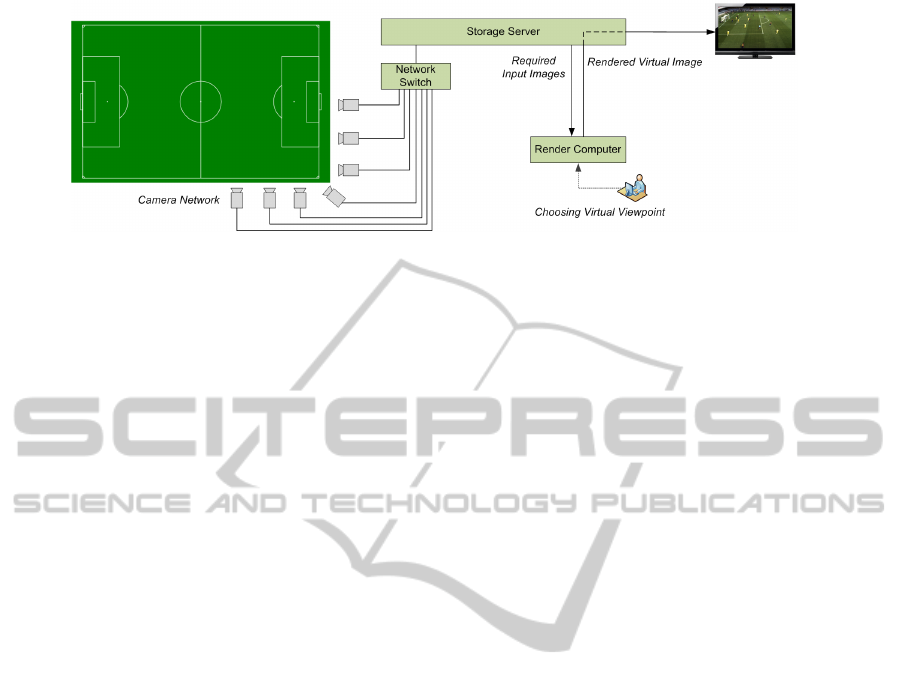
Figure 1: Overview of our setup. The setup consists of a camera network, connected to a storage server. The rendering
module can fetch any image required to generate a novel viewpoint. The novel images are stored on the storage server for
further distribution.
ploy a depth selection method where the acceptable
depths of groups of pixels is determined and used in a
second, depth-selective plane sweep.
To demonstrate our method, we obtained images
from a real soccer match in real conditions. Our
method outperforms other free viewpoint video sys-
tems, as demonstrated by the results and the accompa-
nying video. Typical artifacts, such as ghost players,
are effectively removed.
2 RELATED WORK
There are two general approaches for generating
novel viewpoints using a multiview camera setup:
3D reconstruction and image-based rendering. Using
3D reconstruction, the 3D information is recovered,
allowing the rendering from an arbitrary viewpoint.
The resulting rendering is as good as the reconstruc-
tion. A well-known method is the shape from sil-
houette approach, where foreground-background seg-
mentation is used to reconstruct 3D objects by carving
out voxels in space (Seitz and Dyer, 1999; Kutulakos
and Seitz, 2000), or by reconstructing 3D meshes di-
rectly (Matusik et al., 2000; Miller et al., 2005). The
resulting object, i.e. the visual hull, can then be tex-
tured using the input color images (Eisemann et al.,
2008). While 3D reconstruction is robust, artifacts
can be introduced when the resolution of the 3D ob-
ject is low, or ghosting objects can be introduced if a
lot of objects are in the scene.
Image-based methods do not perform a 3D re-
construction, but will generate the image of a novel
viewpoint directly. These methods include plenop-
tic modeling (McMillan and Bishop, 1995) and light
field rendering (Levoy and Hanrahan, 1996). In many
methods, depth generation, implicit or explicit, is
done concurrently. When using two cameras, stereo
vision can be used (Scharstein and Szeliski, 2002).
Here, explicit depth is calculated, which is used to
warp the input image to a new viewpoint (Glasbey
and Mardia, 1998). While this can introduce holes in
the final result, different techniques are developed to
cope with this problem (Wang et al., 2008). Tradi-
tional stereo methods use a narrow baseline, but ex-
tensions are possible for wide baseline setups using
feature matching (Matas et al., 2002; Tuytelaars and
Van Gool, 2000).
When multiple cameras are present, plane sweep-
ing can be used (Yang et al., 2004). These can be em-
ployed for small baseline setups, such as video con-
ferencing (Dumont et al., 2009), and wide baseline
setups, such as building reconstruction (Baillard and
Zisserman, 2000). Here, different depth hypotheses
are tested for color consistency. This way, depth is
implicitly calculated. Multiple optimizations are pos-
sible, such as depth plane redistribution for higher
quality (Goorts et al., 2013b) or depth omission for
increased performance (Rogmans et al., 2009).
Plane sweeping has already been employed for in-
terpolation in soccer scenes. Goorts et al. (Goorts
et al., 2012a; Goorts et al., 2013a) present a method
with two plane sweeps and a depth filtering step,
but segments in the virtual image can only have
one depth. This will result in disappearing players
if they are overlapping in the image. Furthermore,
the method is only suitable for smaller baseline se-
tups (about 1 meter). Due to the similarity with our
method, thorough comparions are made in Section 6.
Ohta et al.(Ohta et al., 2007) present a free view-
point system for soccer games using billboards. Here,
simple 3D proxies are placed in the scene, represent-
ing players, and the closest camera image is used for
the color information. This will, however, result in
perspective distortions and a lower quality result. Fur-
thermore, player positions can be difficult to estimate
in complex situations.
Hayashi and Saito (Hayashi and Saito, 2006) also
use a billboard method, but the interpolation is per-
formed by estimating the projective geometry among
FreeViewpointVideoforSoccerusingHistogram-basedValidityMapsinPlaneSweeping
379
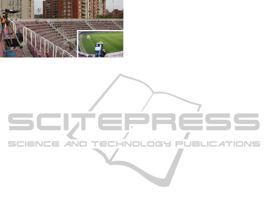
Figure 2: The camera setup. 7 cameras are visible, set up in
an arc arrangement. The distance is 10 meters between the
cameras.
different views.
Germann et al. (Germann et al., 2010) estimate
the pose of the players by matching the images of the
players to a database. This way, novel viewpoints of
players can be calculated, which are then projected
on billboards placed in the scene. This will yield
higher quality results, but manual intervention is re-
quired and the position of the billboards must still be
determined.
Red Bee Media (Corporation, 2001) presented the
iView system (Grau et al., 2007), where a narrow
baseline is used. Both billboards and visual hull are
used. Hilton et al. (Hilton et al., 2011) extend this
method using refinement based on sparse image fea-
tures.
3 ACQUIRING VIDEO STREAMS
We employed a multi camera setup to acquire real
data from soccer scenes. The prototype setup con-
sists of 7 computer vision cameras, placed around one
quarter of the field (see Figure 2). The distance be-
tween the cameras is about 10 meters, allowing the
coverage of a complete field using only 40 cameras.
We used 16 mm Fujinon lenses to provide a field of
view which covers one half of the field, focused on the
center of the penalty area. All cameras were synchro-
nized on shutter level using a global clock. Image data
was transferred using standard 1 gigabit copper Eth-
ernet connections, connected to a switch. The data is
then transferred to a capture computer using a 10 Gi-
gabit fiber Ethernet connection. The images with res-
olution of 1600x1200 are stored in raw, i.e. bayered
format, which reduces the bandwidth with a factor of
three compared with corresponding RGB images.
The setup was tested in real conditions in the Mini
Estadi of Barcelona, Spain, where it proved to be sta-
ble and robust. The quarter arc setup proved to be es-
pecially useful for showing frozen action shots from
different angles. Other setups with a smaller base-
line or a linear camera placement are also possible
(Goorts et al., 2012a). However, we demonstrate a
method where the distance between the cameras is in-
creased, allowing a more flexible and less expensive
setup, thus creating a more practical solution.
4 PREPROCESSING
Before the generation of novel viewpoints is possible,
preprocessing is required.
First, the cameras are calibrated to acquire their
position, orientation and intrinsic parameters. We ex-
tract SIFT features (Lowe, 2004) from a number of
frames and calculate the pairwise matching between
them using the k-d tree algorithm. These pairwise
matches are then tracked across different image pairs.
This way, we obtain point correspondences between
multiple images. Using these image correspondences,
we can calculate the extrinsic and intrinsic parame-
ters simultaneously using the well-known calibration
method of Svoboda et al. (Svoboda et al., 2005).
Here, a bundle adjustment approach is used, together
with an outlier rejector based on RANSAC (Hartley
and Zisserman, 2003). The calibration is then rotated
and scaled such that the pitch is in the XY plane, the
center of the pitch is the center of the coordinate sys-
tem and the unit is in meters. This way, we know the
locations of the cameras relative to the pitch.
Next, the background B
i
of every image stream is
determined. We use a per-pixel median approach ap-
plied to about 30 images per stream, each 2 second
apart from each other. The backgrounds are updated
when the lighting changes during the game. Further-
more, a binary mask of the goal is created.
5 REAL-TIME NOVEL
VIEWPOINT RENDERING
Using the captured image streams and the prepro-
cessed data, we can now render novel viewpoints. The
user of the system chooses a novel viewpoint (or a
collection of novel viewpoints on a viewpath) and the
corresponding time in the sequence. The rendering
request is then processed by the rendering module.
First, the rendering module requests the required
raw images C
r
i
(i ∈ [1, N]) for N cameras from the stor-
age server. Next, the images are debayered and seg-
mented using GPU technologies. These images are
then used in the generation of the image of the novel
viewpoint, where the foreground and background are
rendered independently. The foreground is generated
VISAPP2014-InternationalConferenceonComputerVisionTheoryandApplications
380
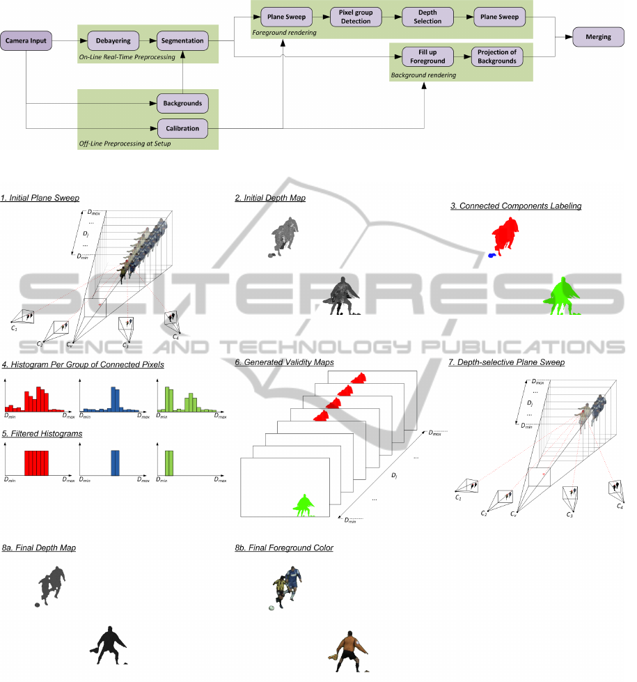
Figure 3: Overview of our method for the rendering. Both the non real-time and real-time phase are shown.
Figure 4: Overview of our method for foreground interpolation. 1: An initial depth map is acquired by a plane sweep
approach. Only the two closest cameras are used for color consistency; the other are used for segmentation consistency. 2:
The initial depth map. Serious artifacts, such as a third leg, can be seen. 3: The depth map is segmented using a parallel
connected components approach. 4: For every group of connected pixels, a depth histogram is acquired. 5: The histogram
is filtered using the depth of the background and depth assumptions. 6: The resulting validity map. Coloured pixels denote a
valid depth; white pixels are non-valid depths. There is a validity map per depth. 7: A second, depth-selective plane sweep is
used, where some depths for a group of pixels are omitted, based on the corresponding validity map. 8a: The final depth map,
and 8b: the corresponding color result.
using a depth-selective plane sweep approach. After
combining foreground and background, the results are
uploaded to the storage server for further distribution.
5.1 Real-time Preprocessing
Every input image for every frame is preprocessed be-
fore further processing. The preprocessing consists of
FreeViewpointVideoforSoccerusingHistogram-basedValidityMapsinPlaneSweeping
381

debayering and segmentation.
Debayering consists of converting raw images to
its RGB representation. In raw images, every pixel
only contains the value of one color channel, as de-
fined by the image sensor; the other color channels
must be estimated. We use the method of Malvar et
al. (Malvar et al., 2004), implemented in CUDA for
fast processing (Goorts et al., 2012b) to estimate the
other, missing color channels. This method uses bi-
linear interpolation, while using gradient information
of other color channels to reduce artifacts. The algo-
rithm can be implemented as FIR filtering.
The debayered images C
i
are then segmented in
foreground and background pixels, represented by the
segmentations S
i
. These segmentations are based on
the backgrounds B
i
, as obtained in Section 4. Seg-
mentation is performed on a per-pixel basis using
the differences between the color values, compared
against three thresholds τ
f
, τ
b
and τ
a
, with τ
f
> τ
b
:
s
i
=
1 : τ
f
< kc
i
− b
i
k
1 : τ
f
≥ kc
i
− b
i
k ≥ τ
b
and cos(
d
c
i
b
i
) ≤ τ
a
0 : kc
i
− b
i
k < τ
b
0 : τ
f
≥ kc
i
− b
i
k ≥ τ
b
and cos(
d
c
i
b
i
) > τ
a
(1)
where s
i
= S
i
(x, y), c
i
= C
i
(x, y) and b
i
= B
i
(x, y),
for all pixels (x, y).
d
c
i
b
i
is the angle between the fore-
ground and background color vectors. This method
allows fast segmentation in high quality. τ
f
and τ
b
allow the determination for very large or very small
differences, while τ
a
considers more subtle color dif-
ferences. Furthermore, we use the mask of the goal to
set all the pixels of the goal to foreground. We want
to actually interpolate the goal to cope with moving
parts and perspective differences in the images. The
segmentation is then enhanced with an erosion and
dilation step to reduce errors caused by input noise
(Yang and Welch, 2002).
The segmentation is applied such that shadows are
part of the background. This will ease the foreground
interpolation, while still keeping lighting information.
Shadows are considered as darker background, reduc-
ing the need for a separate interpolation.
Now the image of the virtual viewpoint can be ren-
dered. The background B
v
and foreground F
v
are pro-
cessed independently.
5.2 Background Rendering
To generate the background B
v
of the virtual image,
we generate the backgrounds of every input image.
Here, the foreground pixels of the input images C
i
are replaced by the corresponding pixels of the back-
grounds B
i
. Now we have the backgrounds of every
input stream, where the shadows and lighting effects
are still present.
These backgrounds are then deprojected to a vir-
tual plane, coplanar to the pitch, and reprojected to
the virtual camera image. We know the location of
the pitch due to the calibration from Section 4. We
start with the camera closest to the virtual camera to
fill the virtual image up as much as possible. The parts
of the image that are not covered by the closest back-
ground are filled up by the other cameras. To provide
a pleasant looking result and to compensate for color
differences between cameras, smoothing is applied to
the borders of the reprojected backgrounds. This way,
changes from one background to the other are not vis-
ible.
The goal is considered as foreground. If the goal
was background, it would be projected to a plane, re-
sulting in serious projective distortions. By consider-
ing the goal as foreground, height of the goal is kept
(just as the players), resulting in higher quality results.
Furthermore, the depth of the virtual background
is stored for further use in the foreground rendering.
5.3 Plane Sweeping
The foreground is rendered using a plane sweep ap-
proach, followed by depth filtering and a depth-
selective plane sweep. The foreground interpola-
tion method is depicted in Figure 4. In the first
step, a depth map is generated using an adaptation
of the well-known plane sweeping method of Yang
et al. (Yang et al., 2003). The space before the virtual
camera is divided in depth planes with distance to the
virtual camera D
p
. We use M planes between D
min
and D
max
.
For every plane, we project the images of the two
cameras p and q closest to the virtual camera onto the
plane. Per pixel, the average γ of the color values is
calculated and used to determine an error value ε:
ε =
kγ −C
p
k
2
+ kγ −C
q
k
2
6
with γ =
C
p
+C
q
2
(2)
Furthermore, the segmentation of every other
camera is projected to the plane. If the segmentation
of one of the cameras is background, ε is set to infin-
ity.
Now we have an error value for every pixel on
the plane. This is repeated for every plane with depth
D
p
∈ [D
min
, D
max
]. We can now generate a depth map
for the virtual image by selecting, for every pixel, the
depth of the plane where the error value ε is minimal.
If ε is infinity for every depth plane, the pixel is con-
sidered as background.
VISAPP2014-InternationalConferenceonComputerVisionTheoryandApplications
382

Using traditional Cg shaders, we can accomplish
real-time processing (Dumont et al., 2009). Com-
pared with CUDA, Cg shaders have projective tex-
turing capabilities and depth testing, thus exploiting
more capabilities of commodity GPUs.
The results of the first plane sweep (already ap-
plied to the background, see Section 5.6) can be seen
in Figure 5. Here, a lot of artifacts can be perceived.
However, the depth map of this result, shown in Fig-
ure 7, shows a very different depth for the artifacts.
We can use this information to filter the depth map
and effectively determine for every pixel the allowed
depth values. This way, we can remove artifacts,
while keeping the depth information of the objects in
the scene.
5.4 Histogram-based Depth Selection
In the depth selection step, we generate a validity
map, i.e. a boolean array with the same size as the
image, for every depth plane. Thus, we generate one
validity map per depth plane. Every element in the
validity map determines if the corresponding pixel
may be processed during the second depth-selective
plane sweeping step. This will exclude certain depths
for certain pixels, thus eliminating artifacts with this
depth.
To determine the allowed depths per pixel, we first
perform a grouping of connected foreground pixels
of the depth map of the virtual image using a paral-
lel connected components algorithm. The connected
components problem consists of labeling every pixel
with a number, where every connected pixel has the
same label and every group of non-connected pixels
has a different label. This way, we perform a map-
ping between a label and a group of connected pixels.
Initially, we apply a unique label to every pixel
and apply zero to background pixels. Next, we com-
pare every pair of neighboring pixels. If one of the
two labels is zero, nothing happens. If the labels are
greater than zero and different, both labels are set to
the smallest of the two. By repeating this process un-
til no changes are performed anymore, all connected
pixels will have the same label.
This method can be mapped to the model of
CUDA. Every pixel is assigned a thread on the GPU,
so that these are processed in parallel. Because only
neighboring pixels are considered, fast memory ac-
cess strategies can be employed by using only loca-
lized memory accesses. This allows the use of fast,
thread-shared memory and reduces the amount of
slow copies from global memory (Goorts et al., 2009).
Once all groups of connected pixels have the same
label, we can generate the histogram of depth val-
ues per group using parallel reduction. Once the his-
tograms are known, we apply a local maximum filter-
ing where we replace the value of the histogram by the
maximum value in its neighborhood. A neighborhood
of size φ
e
is used. This way, we can effectively filter
out peaks in the histogram, which are considered valid
depth values. By using a neighborhood, depth values
around the valid depths are still considered, allowing
more detailed depth maps in the final result.
Furthermore, we remove all values that differ too
much from the depths of the backgrounds using a
threshold φ
b
. This will eliminate depths where the
objects should be in the ground or flying high in the
air. Lastly, we delete all histograms with less than φ
h
values, thus eliminating noise.
Once these filtered histograms are known, we use
these to generate the validity map per depth value,
which determines if that depth for a pixel is valid.
For every pixel in the depth map, we determine the
corresponding label and look up the value of the his-
togram of the corresponding label. If the value is a
local maximum in the histogram, the depth is valid
and is as such represented in the validity map. This
validity map is created for every processed depth and
passed to the second depth-selective plane sweep. By
using a histogram-based method, multiple depths and
various depth ranges are possible per group of pixels,
allowing situations with many players close to each
other.
5.5 Depth-selective Plane Sweep
The second, depth-selective plane sweep is equivalent
to the first plane sweep, but the error value ε is set to
infinity if the depth of the plane is not valid, according
to the validity maps from the previous filtering step. It
is possible that all error values ε for a pixel are infin-
ity, thus resulting in background and the effective re-
moval of artifacts. To increase performance, the num-
ber of valid pixels in the validity map is counted. If
the value is zero, the plane is skipped. The final color
result consists of the average color values γ where ε is
minimal.
5.6 Merging
At this point, the background of the virtual image is
known from Section 5.2, and the foreground with seg-
mentation information from Section 5.5. The fore-
ground and background are merged together accord-
ing to the segmentation information. This will result
in the final image with correct shadows and reduced
artifacts.
FreeViewpointVideoforSoccerusingHistogram-basedValidityMapsinPlaneSweeping
383
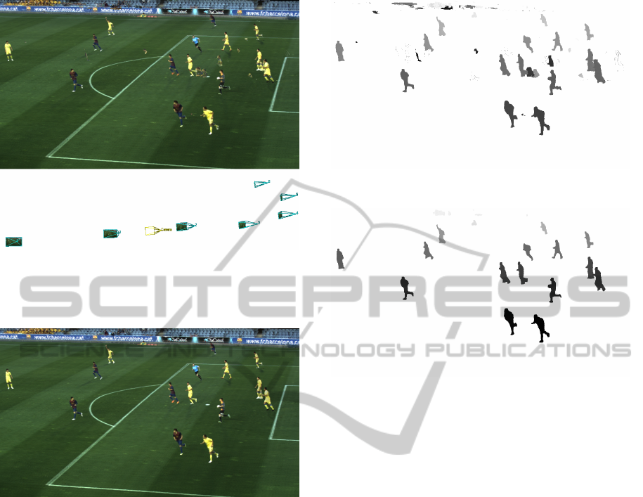
Figure 5: Result of traditional interpolation methods. The
position of the virtual camera, in yellow, is shown beneath
the result. Artifacts, such as ghosting players and ghost
limbs, can be clearly seen.
Figure 6: Result of our method, at the same position for
the virtual camera as Figure 5. The artifacts are effectively
removed.
6 RESULTS
To demonstrate the effectiveness of our method, we
used real captured data from a real soccer game. We
use 1024 planes for the plane sweeping step and use
the values φ
e
= 9, φ
b
= 0.03 (for depths normalized
between 0 and 1) and φ
h
= 20 pixels. This parame-
ters will result in the highest visible quality. By using
an NVIDIA Geforce GTX Titan, we obtain a process-
ing speed of 6Hz for the full resolution of 1600x1200.
Due to the parallel nature and temporal independence
of the method, scalability can easily be obtained by
increasing the number or GPUs per system or by in-
creasing the number of rendering computers.
Figure 5 shows the results using traditional plane
sweeping approaches, without depth filtering. The
corresponding depth map is shown in Figure 7. Nu-
merous artifacts can be perceived. Figure 6 and Fig-
Figure 7: Depth map of the result of traditional interpolation
methods of Figure 5. The depth of the artifacts is clearly
different from the depth of the correct objects.
Figure 8: Depth map of the result of our method of Figure
6.
ure 8 shows the result for our approach. As can be
seen, the artifacts are effectively removed.
This is further demonstrated in detail in Figure 9.
Here, a closed up view shows that there is a ghost leg
and other ghosting artifacts. As shown in Figure 9(b),
these kind of artifacts are effectively removed.
When using only one depth value per group of pix-
els, as proposed by Goorts et al. (Goorts et al., 2013a),
players can disappear when using a wide baseline
setup. This is demonstrated in Figure 10. Here, the
closest player at the right side has disappeared. Fig-
ure 11 shows out method. Here, all players are visible
and no disappearance can be perceived.
Some artifacts can still be perceived in the back-
ground, such as ghost lines. This is caused by the sim-
plified assumption of the geometry of the pitch. When
more accurate geometric data is available, quality will
increase.
All results can also be seen in the supplementary
video, where our method is demonstrated using real
life soccer data. Here, a smooth transition from one
side to the other is demonstrated, both for a moving
and a frozen scene. This clearly demonstrates the use
of our method to generate a virtual rail camera, us-
ing only 7 static cameras. Furthermore, the method
is compared side-by-side with traditional methods,
where artifacts can be seen.
VISAPP2014-InternationalConferenceonComputerVisionTheoryandApplications
384
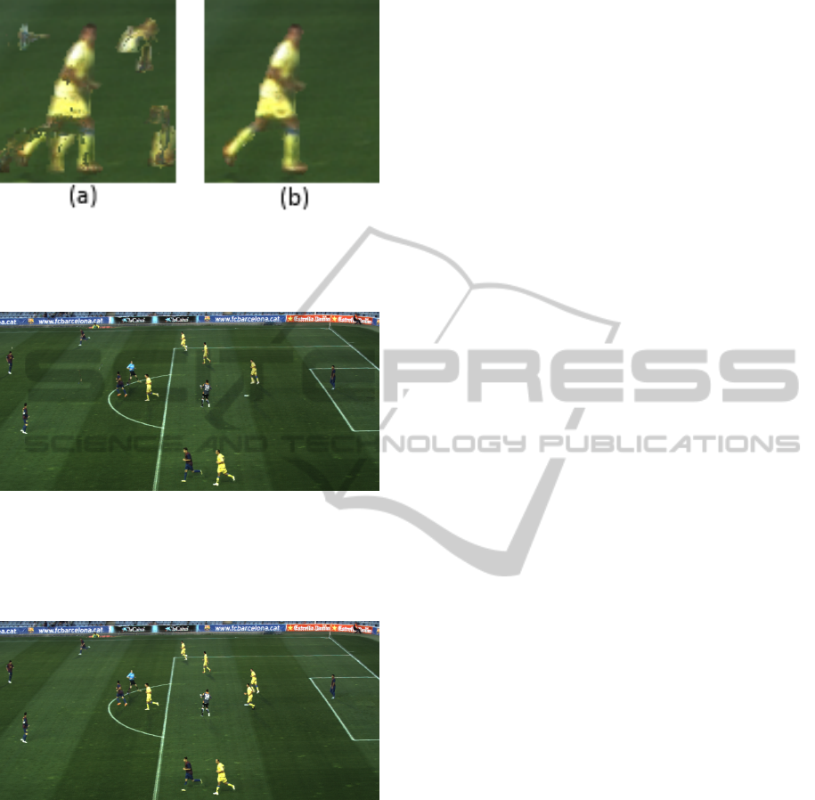
Figure 9: (a) Detail result of traditional interpolation meth-
ods. Artifacts, such as ghost players and ghost limbs, can
clearly be seen. (b) Detail result of our method. The arti-
facts are effectively removed.
Figure 10: Results generated using the method of Goorts
et al. (Goorts et al., 2013a). When compared with Fig-
ure 11, a player has disappeared (the closest player of the
group of two players at the right side). This is caused by the
invalid assumption that every group of pixel only has one
valid depth.
Figure 11: Result of our method. No players have disap-
peared, or have been filtered out.
7 CONCLUSIONS
We presented our system to generate free viewpoint
video for soccer games, using a wide baseline static
camera setup. Our method uses and extends the well-
known plane sweep approach, allowing the genera-
tion of higher quality results. We employ an initial
plane sweep to generate a crude depth map. This
depth map is filtered and used for a second, depth-
selective plane sweep. By employing a combination
of traditional Cg and modern NVIDIA CUDA GPU
computing, a scalable and fast solution is obtained.
The results, obtained from real life data, demonstrate
the effectiveness of our method, where the artifacts
from traditional approaches are effectively removed,
resulting in high quality images for the virtual cam-
era.
ACKNOWLEDGEMENTS
Patrik Goorts would like to thank the IWT for its PhD.
bursary.
REFERENCES
Baillard, C. and Zisserman, A. (2000). A plane-sweep strat-
egy for the 3d reconstruction of buildings from multi-
ple images. International Archives of Photogramme-
try and Remote Sensing, 33(B2; PART 2):56–62.
Corporation, R. B. (2001). 3d graphics systems. http:
//www.redbeemedia.com/piero/piero.
Dumont, M., Rogmans, S., Maesen, S., and Bekaert, P.
(2009). Optimized two-party video chat with restored
eye contact using graphics hardware. e-Business and
Telecommunications, pages 358–372.
Eisemann, M., De Decker, B., Magnor, M., Bekaert, P.,
De Aguiar, E., Ahmed, N., Theobalt, C., and Sellent,
A. (2008). Floating textures. Computer Graphics Fo-
rum, 27(2):409–418.
Germann, M., Hornung, A., Keiser, R., Ziegler, R.,
W
¨
urmlin, S., and Gross, M. (2010). Articulated bill-
boards for video-based rendering. Computer Graphics
Forum, 29(2):585–594.
Glasbey, C. A. and Mardia, K. V. (1998). A review of
image-warping methods. Journal of applied statistics,
25(2):155–171.
Goorts, P., Ancuti, C., Dumont, M., and Bekaert, P. (2013a).
Real-time video-based view interpolation of soccer
events using depth-selective plane sweeping. In Pro-
ceedings of the Eight International Conference on
Computer Vision Theory and Applications (VISAPP
2013). INSTICC.
Goorts, P., Dumont, M., Rogmans, S., and Bekaert, P.
(2012a). An end-to-end system for free viewpoint
video for smooth camera transitions. In Proceedings
of the Second International Conference on 3D Imag-
ing (IC3D 2012). 3D Stereo Media.
Goorts, P., Maesen, S., Dumont, M., Rogmans, S., and
Bekaert, P. (2013b). Optimization of free viewpoint
interpolation by applying adaptive depth plane dis-
tributions in plane sweeping. In Proceedings of the
Eleventh International Conference on Signal Process-
ing and Multimedia Applications (SIGMAP 2013).
Goorts, P., Rogmans, S., and Bekaert, P. (2009). Opti-
mal Data Distribution for Versatile Finite Impulse Re-
sponse Filtering on Next-Generation Graphics Hard-
ware using CUDA . In Proceedings of The Fifteenth
FreeViewpointVideoforSoccerusingHistogram-basedValidityMapsinPlaneSweeping
385

International Conference on Parallel and Distributed
Systems, pages 300–307.
Goorts, P., Rogmans, S., and Bekaert, P. (2012b). Raw
camera image demosaicing using finite impulse re-
sponse filtering on commodity gpu hardware using
cuda. In Proceedings of the Tenth International Con-
ference on Signal Processing and Multimedia Appli-
cations (SIGMAP 2012). INSTICC.
Grau, O., Hilton, A., Kilner, J., Miller, G., Sargeant, T., and
Starck, J. (2007). A Free-Viewpoint Video System for
Visualization of Sport Scenes. SMPTE motion imag-
ing journal, 116(5/6):213.
Hartley, R. and Zisserman, A. (2003). Multiple view geom-
etry in computer vision, volume 2. Cambridge Univ
Press.
Hayashi, K. and Saito, H. (2006). Synthesizing Free-
Viewpoing Images from Multiple View Videos in Soc-
cer Stadium. In Proceedings of the International Con-
ference on Computer Graphics, Imaging and Visuali-
sation, pages 220–225.
Hilton, A., Guillemaut, J., Kilner, J., Grau, O., and Thomas,
G. (2011). 3d-tv production from conventional cam-
eras for sports broadcast. IEEE Transactions on
Broadcasting, (99):1–1.
Kutulakos, K. and Seitz, S. (2000). A theory of shape by
space carving. International Journal of Computer Vi-
sion, 38(3):199–218.
Levoy, M. and Hanrahan, P. (1996). Light field rendering. In
Proceedings of the 23rd annual conference on Com-
puter graphics and interactive techniques, pages 31–
42. ACM.
Lowe, D. (2004). Distinctive image features from scale-
invariant keypoints. International journal of computer
vision, 60(2):91–110.
Malvar, H., He, L., and Cutler, R. (2004). High-quality lin-
ear interpolation for demosaicing of bayer-patterned
color images. In Proceedings of the International
Conference on Acoustics, Speech, and Signal Process-
ing (ICASSP 2004), volume 3, pages 485–488. IEEE.
Matas, J., Chum, O., Urban, M., and Pajdla, T. (2002). Ro-
bust wide baseline stereo from maximally stable ex-
tremal regions. In Proceedings of the British machine
vision conference, volume 1, pages 384–393.
Matusik, W., Buehler, C., Raskar, R., Gortler, S., and
McMillan, L. (2000). Image-based visual hulls. In
Proceedings of the 27th annual conference on Com-
puter graphics and interactive techniques, pages 369–
374. ACM Press/Addison-Wesley Publishing Co.
McMillan, L. and Bishop, G. (1995). Plenoptic modeling:
An image-based rendering system. In Proceedings
of the 22nd annual conference on Computer graphics
and interactive techniques, pages 39–46. ACM.
Miller, G., Hilton, A., and Starck, J. (2005). Interac-
tive free-viewpoint video. In Proceedings of the In-
ternational Conference on Visual Media Production
(CVMP 2005), pages 50–59. Citeseer.
Ohta, Y., Kitahara, I., Kameda, Y., Ishikawa, H., and
Koyama, T. (2007). Live 3D Video in Soccer Stadium.
International Journal of Computer Vision, 75(1):173–
187.
Rogmans, S., Dumont, M., Cuypers, T., Lafruit, G., and
Bekaert, P. (2009). Complexity reduction of real-time
depth scanning on graphics hardware. In Proceedings
of the International Conference on Computer Vision
Theory and Applications (VISAPP 2009).
Scharstein, D. and Szeliski, R. (2002). A taxonomy and
evaluation of dense two-frame stereo correspondence
algorithms. International journal of computer vision,
47(1):7–42.
Seitz, S. and Dyer, C. (1999). Photorealistic scene recon-
struction by voxel coloring. Inernational. Journal of
Computer Vision, 35(2):151–173.
Svoboda, T., Martinec, D., and Pajdla, T. (2005). A conve-
nient multicamera self-calibration for virtual environ-
ments. Presence: Teleoperators & Virtual Environ-
ments, 14(4):407–422.
Tuytelaars, T. and Van Gool, L. (2000). Wide baseline
stereo matching based on local, affinely invariant re-
gions. In Proceedings of the British machine vision
conference, volume 2, page 4.
Wang, L., Jin, H., Yang, R., and Gong, M. (2008). Stereo-
scopic inpainting: Joint color and depth completion
from stereo images. In Proceedings of the Interna-
tional Conference on Computer Vision and Pattern
Recognition (CVPR 2008), pages 1–8. IEEE.
Yang, R., Pollefeys, M., Yang, H., and Welch, G. (2004). A
unified approach to real-time, multi-resolution, multi-
baseline 2d view synthesis and 3d depth estimation
using commodity graphics hardware. International
Journal of Image and Graphics, 4(4):627–651.
Yang, R. and Welch, G. (2002). Fast image segmentation
and smoothing using commodity graphics hardware.
Journal of graphics tools, 7(4):91–100.
Yang, R., Welch, G., and Bishop, G. (2003). Real-time
consensus-based scene reconstruction using commod-
ity graphics hardware. Computer Graphics Forum,
22(2):207–216.
VISAPP2014-InternationalConferenceonComputerVisionTheoryandApplications
386
