
An Improved Approach for Depth Data based Face Pose Estimation
using Particle Swarm Optimization
Xiaozheng Mou and Han Wang
School of Electrical and Electronic Engineering, Nanyang Technological University, 639798, Singapore, Singapore
Keywords:
Template Matching, Nose Tip Localization, Face Orientation Computation.
Abstract:
This paper presents an improved approach for face pose estimation based on depth data using particle swarm
optimization (PSO). In this approach, the frontal face of the system-user is first initialized and its depth image
is taken as a person-specific template. Each query face of that user is rotated and translated with respect to its
centroid using PSO to match with the template. Since the centroid of each query face always changes with the
face pose changing, a common reference point has to be defined to measure the exact transformation of the
query face. Thus, the nose tips of the optimal transformed face and the query face are localized to recompute
the transformation from the query face to the optimal transformed face that matched with the template. Using
the recomputed rotation and translation information, finally, the pose of the query face can be approximated
by the relative pose between the query face and the template face. Experiments on public database show that
the accuracy of this new method is more than 99%, which is much higher than the best performance (< 91%)
of existing work.
1 INTRODUCTION
Face pose estimation or head pose estimation is an
important and challenging task for many real life ap-
plications, such as human-computer interfaces (e.g.,
monitoring drivers attention in a car), preprocessing
for face registration and face recognition, and visual
gaze estimation, in which face pose provides an im-
portant supplementary information. Thus, numerous
research (Murphy-Chutorian and Trivedi, 2009) con-
centrated on the issue of face pose estimation have
emerged prominently in the last few years.
Recently, with the development of 3D scanning
technology, like real-time stereo-enhanced structured-
light method (Weise et al., 2007), Microsoft Kinect,
etc, 3D data with high resolution and accuracy can be
obtained conveniently. Since 3D data is much less af-
fected by illumination changing and partial occlusion
of the face (e.g. hair, glasses) than 2D data (RGB
image or intensity image), recent researches for face
pose estimation based on 3D data demonstrated more
accurate and robust results. In general, the methods
for this 3D data based study can be grouped into three
classes: models method, regression method and align-
ment method.
In models method, 3D face model is always con-
structed from the facial features, landmarks, surface,
or point clouds. With the generated model, related
mathematic methods are used to solve the face pose.
For example, (Cai et al., 2010) constructed their 3D
face model using the linear deformable model (Zhang
et al., 2004), and the face pose is obtained by comput-
ing the rotation, translation and deformation param-
eters between the head model and the depth camera
with a regularized maximum likelihood deformable
model fitting algorithm. (Bleiweiss and Werman,
2010) combined the color data with the time-of-flight
depth data to construct a textured mesh model, and
then synthetic image was obtained by projecting the
hypotheses mesh model to 2D image space. The head
pose is finally derived by minimizing the difference
between the synthetic image and input image. More-
over, A rigid body motion model (Horn and Harris,
1991) is applied in (Kondori et al., 2011) to measure
the face rotation and translation between two consec-
utive depth frames. In (Tu et al., 2011), the pitch and
yaw angles are estimated by fitting a plane to the 3D
points around the detected nose tip, while the roll an-
gle is coarsely computed by fitting an ellipse to the
head boundary points. However, the accuracy of this
method is limited by the robustness of nose tip detec-
tion or nose tip tracking.
The regression method is efficient to solve the
problem of face pose estimation for the reason that
534
Mou X. and Wang H..
An Improved Approach for Depth Data based Face Pose Estimation using Particle Swarm Optimization.
DOI: 10.5220/0004732305340541
In Proceedings of the 9th International Conference on Computer Vision Theory and Applications (VISAPP-2014), pages 534-541
ISBN: 978-989-758-004-8
Copyright
c
2014 SCITEPRESS (Science and Technology Publications, Lda.)

features extracted from the depth image are discrimi-
nately enough and robust to illumination and partial
occlusion. For instance, (Tang et al., 2011a; See-
mann et al., 2004) employed neural network (NN) to
train and test their 3D face pose estimators. (Rajwade
and Levine, 2006) utilized support vector regression
(SVR) based on 3D data to estimate facial pose. Fur-
thermore, random regression forests (RRF) is utilized
in (Fanelli et al., 2011a; Fanelli et al., 2011b; Tang
et al., 2011b) to solve depth data based face pose esti-
mation problem. However, a large database has to be
collected for training in the regression method.
In alignment method, the query face image is first
aligned with a fixed template face image, and then
the pose of the query face is measured by the orienta-
tion difference between them. Iterative closest point
(ICP) (Besl and McKay, 1992) is a commonly used
approach for 3D point clouds alignment. Numerous
papers (Ghorbelet al., 2010; Mora and Odobez, 2012)
have applied ICP to solve the task of 3D face pose
estimation. Nevertheless, ICP need a good initial-
ization, and it is sensitive to facial expression chang-
ing and oblique face poses. These limitations invoke
other methods to improve the robustness and reduce
the limitations. (Breitenstein et al., 2008) proposed a
real time face pose estimation system based on sin-
gle range images. Nevertheless, several limitations
exist in their work: 1) a huge database with face mod-
els of different reference poses should be prepared;
2) the space of face poses is discretized, which may
reduce the accuracy; 3) the nose detection part is com-
plicate and time consuming. Evolutionary algorithm
(EA) (Back, 1996) for face pose estimation was first
published in (Padeleris et al., 2012). In their work,
particle swarm optimization (PSO) is used to regis-
ter the resampled candidate face to the template face.
Furthermore, (Wang and Ying, 2012) employed ge-
netic algorithm (GA) to register two point clouds of
partial faces to recover the whole face, and it showed
better performance on this task than ICP.
Therefore, in the above literatures, either training
is required or the accuracy is limited by large pose
variations. Inspired by the work of (Padeleris et al.,
2012) by Padeleris et al., this paper presents an im-
proved approach for face pose estimation based on
depth data. Unlike (Padeleris et al., 2012), in the pro-
posed algorithm, we get rid of the processes of sur-
face reconstruction and depth image resampling, but
utilize the PSO algorithm on the original depth image
directly for template matching, which results in two
corresponding point clouds between the query face
and the optimal transformed face. Moreover, the nose
tips on the two corresponding point clouds can be lo-
calized precisely by the proposed method. Finally,
with the obtained corresponding points and nose tips
mentioned above, the relative rotation and translation
matrices of the query face to the optimal transformed
face or template face can be derived using the singu-
lar value decomposition (SVD) algorithm. Therefore,
the estimated orientation of the query face can be ob-
tained from the rotation and translation matrices by
assuming the orientation angles of the template face
are all zero degree. The proposed algorithm is ex-
pected to be faster and more accurate than the method
proposed in (Padeleris et al., 2012). An overview of
the proposed framework is shown in Figure 1.
The remainder of the paper is organized as fol-
lows: The proposed approach for face pose estimation
is described in detail in Section 2; Experimental re-
sults are presented in Section 3 to verify the efficiency
of the proposed approach; A conclusion is made and
the future work for this study is discussed in Section
4.
2 PROPOSED APPROACH
In this paper, the face pose, P = [ρ η γ x y z]
T
, is com-
posed by the nose tip location (x,y,z) and face orien-
tation (ρ, η, γ) (pitch, yaw, roll angles). Suppose the
face is already segmented, the organized point cloud
of the face whose pose needs to be estimated is named
as query face denoted by Q ∈ R
m×n×3
. Denote that
M ∈ R
m×n
is the template face depth image (2D map
of z values), and F
o
∈ R
m×n
is the optimal depth im-
age transformed from Q.
2.1 Template Matching
The first goal of the proposed algorithm is to align
the depth image of query face Q to the template face
depth image M and obtain the optimal transformed
depth image F
o
. To this end, as (Padeleris et al.,
2012), this alignment process can be formulated by
minimizing the Sum of Squared Differences (SSD)
of pairwise pixel differences between the template M
and the face depth image F
k
∈ R
m×n
, which is trans-
formed from Q by several candidate parameters: scal-
ing scalar c
k
∈ R
+
, rotation matrix R
k
∈ R
3×3
and
translation matrix T
k
∈ R
3×1
. Hence, this optimiza-
tion problem can be formulated by
arg min
c
k
,R
k
,T
k
= ξ
−1
m
∑
i=1
n
∑
j=1
H(i, j)[M(i, j) − F
k
(i, j)]
2
,
(1)
where ξ =
m
∑
i=1
n
∑
j=1
H(i, j) is a normalization factor and
H(i, j) is a point matching indicator:
AnImprovedApproachforDepthDatabasedFacePoseEstimationusingParticleSwarmOptimization
535
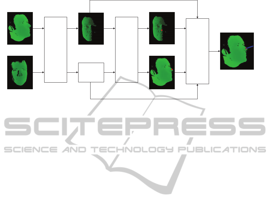
Template face
Query face
Face
Alignment
(PSO)
Optimal
transformed
face
Corresponding
points matrix
Nose
Tip
Localization
Nose tip of
transformed
face
Nose tip of
query face
Rotation
Matrix
Computing
(SVD)
Query face
orientation
Figure 1: Flowchart of the proposed approach for face pose estimation based on depth data.
H(i, j) =
(
1, if F
k
(i, j) > 0 and M(i, j) > 0
0, otherwise.
(2)
Denote q
l
∈ R
3×1
,l = [1,2, ..., mn] as a 3D point
in point cloud Q, and w ∈ R
3×1
is the centroid of Q.
Then, for each point in Q with depth value greater
than 0, the following transformation is conducted:
f
l
= c
k
R
k
· (q
l
− w) + T
k
, (3)
in which f
l
∈ R
3×1
is called the corresponding point
of q
l
.
The transformed face depth image F
k
is formed
by projecting each f
l
to a void m× n 2D matrix. The
pixel value of F
k
is determined by the depth (z) value
of the point projected upon that pixel location. How-
ever, there is a case that more than one points may be
projected to a same 2D pixel location. In this case, the
pixel value of F
k
in that location is set by the small-
est depth value of all points projected on it. Mean-
while, the transformed face point cloud F
′
k
∈ R
m×n×3
corresponding to F
k
can be obtained with the points
that form F
k
. Similarly, with the corresponding re-
lationship of f
l
and q
l
, the corresponding points ma-
trix Q
′
k
∈ R
m×n×3
of F
′
k
can be formed by putting the
corresponding points of F
′
k
into Q
′
k
with the same 2D
location.
Similar to (Padeleris et al., 2012), the canonical
PSO is applied to solve the minimization problem
proposed in formula (1). In PSO, each particle is a
candidate solution for the fitness function (1), and the
particle is modelled by a seven dimensional vector
s = [c φ θ ψ d
x
d
y
d
z
]
T
, where c is the scaling fac-
tor; φ,θ,ψ are the rotation Euler angles correspond-
ing to x, y and z axes respectively; d
x
,d
y
,d
z
denotes
the translation along x, y and z axes. Note that the ori-
gin of the coordinate system mentioned above is the
centroid of the query face point cloud.
Assuming the optimal solution of (1) is found us-
ing PSO, the indicator k for all parameters mentioned
above is replaced with o. However, this optimal solu-
tion is not the accurate face pose, because the centroid
of the query face is not the corresponding point of the
centroid of the template face, which results in mean-
ingless rotation Euler angles and translation values for
face pose. Therefore, to compute accurate face pose,
a reference point has to be defined.
2.2 Nose Tip Localization
Finding that nose tip is a good reference point which
is invariant to the changes of face expression and easy
to locate automatically, we measure the query face
orientation around its nose tip (face location). In this
part, a simple hybrid method for nose tip localization
is proposed.
Method 1. Normally, the nose tip of a frontal face
point cloud is the nearest point to the camera. Thus,
one method of localizing the nose tip is to find the
point with smallest depth value in the optimal trans-
formed face depth image F
o
, and then use the opti-
mal transformed face point cloud F
′
o
to obtain the 3D
nose tip point ∆
f
in it. Meanwhile, the 3D nose tip
point ∆
q
in the query face point cloud Q can be ob-
tained by finding the corresponding points of F
′
o
in
its corresponding points matrix Q
′
o
. However, find-
ing only one point with smallest depth value in the
point cloud may produce wrongly located nose tip
caused by noisy points, and it may need a large num-
ber of computing time when the searching space is
the whole face image. To solve the problems men-
tioned above, a constrained nose region is predefined
for nose tip searching. First, the nose of the template
face is detected on its RGB image using object de-
VISAPP2014-InternationalConferenceonComputerVisionTheoryandApplications
536
tection method(e.g. Viola-Jones method); If the RGB
image is not available (suppose the depth image or
3D point cloud of the template face is already seg-
mented), the nose region can be roughly defined by
computing the center of the point cloud, which means
the 2D location of the point cloud center is the same
with the center of the nose region. After defining the
nose tip searching region on the template face, this re-
gion is fixed and applied to all the transformed frontal
faces, since the relative 2D locations of the template
image and the optimal transformed image are iden-
tical. Rather than only selecting only one point in
the predefined searching region, N
m1
points in F
′
o
with
smallest depth values are selected and taken the aver-
age of these 3D points, which results in the nose tip
∆
f
of the optimal transformedface. Accordingly,with
Q
′
o
, the nose tip ∆
q
of the query face can be derived
by computing the average of the corresponding points
of the selected N
nose
points in F
′
o
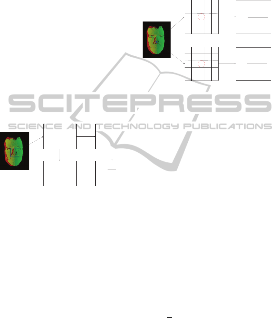
. The procedure of
Method 1 is depicted in Figure 2.
},...,,{
1
21
m
N
fff
Points with smallest
depth value found
from the nose region
of the optimal
transformed face
å
=
=
D
1
1
1
1
m
N
i
i
m
f
f
N
Nose tip of the optimal
transformed face
å
=
=
D
1
1
1
1
m
N
i
i
m
q
q
N
Nose tip of the query
face
}
,...,,
{
1
21
m
N
qq
q
Points with smallest
depth value in the
query face
Corresponding
points matrix
Figure 2: Method 1 for nose tip localization. In the left im-
age, Green: template face; Red: optimal transformed face;
Yellow: matching points between the template face and the
optimal transformed face.
Method 2. Another method for nose tip localization
is similar to Method 1, but more time saving and more
insensitive to noise. In this method, the nose tip of the
template face is localized using the same means of
Method 1. However, instead of searching points with
smallest depth value in the predefined nose region, the
2D location of the nose tip on the template face im-
age is considered as the 2D location of the nose tip
on the optimal transformed face image. In this way,
the nose tips of the transformed face and the query
face are localized by averaging the N
m2
× N
m2
neigh-
borhood 3D points of the pre-computed 2D nose tip
location in F
′
o
and Q
′
o
respectively. Nevertheless, for
some large rotation angles, the N
m2
× N
m2
neighbor-
hood 3D points may contain no information, and this
method will not detect any nose tip in such case. Fig-
ure 3 illustrates this method. Note that in Figure 3,
h
i, j
= 1, if the depth value of f
i, j
is greater than 0;
Otherwise, h
i, j
= 0. h
′
i, j
= 1, if the depth value of
q
i, j
is greater than 0; Otherwise, h
′
i, j
= 0. This means
the neighborhoodpoints to be averaged in this method
should have depth values greater than zero.
11
f
14
f
13
f
12
f
21
f
15
f
25
f
24
f
23
f
22
f
55
f
54
f
53
f
52
f
51
f
45
f
44
f
43
f
42
f
41
f
35
f
34
f
32
f
31
f
33
f
51
q
45
q
44
q
43
q
42
q
41
q
35
q
34
q
33
q
32
q
31
q
25
q
24
q
23
q
22
q
21
q
15
q
14
q
12
q
11
q
55
q
13
q
54
q
53
q
52
q
Neighborhood 3D points in
the optimal transformed
face
Neighborhood 3D points in
the corresponding points
matrix
å å
å å
= =
= =
=D
2 2
2 2
1 1
1 1
m m
m m
N
i
N
j
ij
N
i
N
j
ijij
f
h
fh
åå
åå
= =
= =
=D
2 2
2 2
1 1
'
1 1
'
m m
m m
N
i
N
j
ij
N
i
N
j
ijij
q
h
qh
Nose tip of the optimal
transformed face
Nose tip of the query face
Figure 3: Method 2 for nose tip localization. In the left im-
age, Green: template face; Red: optimal transformed face;
Yellow: matching points between the template face and the
optimal transformed face.
Method 3. In our work, to combine the advantages
of the above two methods for nose tip localization,
we propose to apply Method 2 first, and if no nose
tip was detected, Method 1 is used to detect the nose
tip. In this hybrid method, both the nose tip and nose
region of the template face need to be found and re-
tained before estimating the pose of the query face,
while this process is fully automatic and fast. Since
the case of very large face rotation is rare, the hybrid
method not only reduces the computation complex-
ity (avoiding the point searching procedure for most
cases), but also improves the robustness of nose tip
localization (reducing the influence of noise).
Thus, with F
′
o
and Q
′
o
, the nose tip ∆
f
∈ R
3×1
of the optimal transformed face F
′
o
and the nose tip
∆
q
∈ R
3×1
of the query face Q can be localized re-
spectively.
2.3 Face Orientation Computation
At last, the orientation of the query face can be de-
rived by finding the rotation and translation relation-
ship with respect to the face location (nose tip) be-
tween F
′
o
and Q
′
o
, which is formulated by the follow-
ing least square problem.
argmin
R,T
1
N
N
∑
i=1
k( f
′
i
− ∆
f
) − [R(q
′
i
− ∆
q
) + T]k
2
, (4)
where f
′
i
∈ R
3×1
and q
′
i
∈ R
3×1
are corresponding
points in F
′
o
and Q
′
o
respectively; N is the number of
points with depth value greater than zero.
AnImprovedApproachforDepthDatabasedFacePoseEstimationusingParticleSwarmOptimization
537

The minimization problem in (4) can be easily
solved using SVD. Note that R and T obtained in
(4) represent the rotation and translation from the
query face Q to the optimal transformed face F
′
o
. Be-
cause the optimal transformed face has been already
aligned with the template face based on depth data
(z value) using PSO, it can be approximated that R
and T are also the motion parameters from the query
face to the template face. Assume that the reference
rotation matrix R
0
and translation vector T
0
of the
initialized template face are R
0
= I
3×3
(3 × 3 iden-
tity matrix) and T
0
= [0 0 0]
T
, respectively. There-
fore, take the forward direction vector of the template
face as
~
d
0
∈ R
3×1
, then the forward direction vector
~
d
q
∈ R
3×1
of the query face can be obtained by taking
the inverse translation and rotation. That is
~
d
q
= R
T
(
~
d
0
− T). (5)
In the end, the desired pitch and yaw angles of the
query face Q can be easily derived by the obtained
direction vector
~
d
q
. Similarly, the roll angle can also
be derived with the same method by defining a ver-
tical direction vector that is perpendicular to
~
d
q
. In
other words, if the forward direction vector parallels
to z axis, the vertical direction vector to compute roll
angle should parallel to y axis.
3 EXPERIMENTS
In order to assess the efficiency of the proposed al-
gorithm for face pose estimation based on 3D data,
the ETH Face Pose Range Image Data Set (Breit-
enstein et al., 2008) is used. In this database, more
than 10,000 range images (i.e. images with per-pixel
depth, also known as depth images) of 20 persons (3
female, 6 persons of them recorded twice for the sit-
uations with and without glasses) are included. The
range images were captured at 28 fps with a scan-
ner using the real-time stereo-enhanced structured-
light method (Weise et al., 2007) when each people
first looked straight into the camera, and then freely
turned her head. Each range image has a resolution
of 640 × 480 pixels, and a face typically consists of
about 150 × 200 depth values. The face pose range
covers about ±90
◦
for yaw rotation and ±45
◦
for
pitch rotation. Nose position and face direction (vec-
tor through nose) in a left-handed coordinate system
of each range image were provided as ground truth.
All the experiments in this section are performed on a
PC equipped with i5 3.10GHz CPU.
Throughout our experiments, the size of each face
range image is set to 200× 260 pixels. In the part of
face alignment using PSO, the following parameters
are predefined: Since the first range image in each
sequence was taken when the person looked straight
into the camera, we take this image as the person-
specific initialization, where the person-specific tem-
plate face depth image with assumed face direction
~n = [0,0, −1] is obtained. The number of particles
is set to S = 25, and the maximum running genera-
tions are tested by G = 10, 20, 30, 40 separately. For
simplification, the scaling factor c in the first dimen-
sion of each particle is taken as c = 1, because there
is little scaling variation in the sequence of each per-
son, who was asked to just rotate her head but not to
move forward or back when recording the database.
In addition, the rotation angles and translation dis-
tance dimensions of each particle are initialized at
the uniform distribution of the center of the search-
ing space, while their velocities are set to zeros. Be-
cause each sequence in the database is continuous, i.e.
the poses of every two consecutive images have rela-
tive small difference, the optimal solution of the pre-
vious image is taken as the searching center of cur-
rent image, and the searching space around the center
is defined as ±20
◦
for each rotation angle dimension
(φ,θ,ψ) and ±20mm for each translation dimension
(d
x
,d
y
,d
z
). This searching space constriction method
both accelerate the searching speed for optimal solu-
tion and improve the face alignment accuracy. Fur-
thermore, in the particle velocity update equation, we
take the same parameters setting and constraints as
(Padeleris et al., 2012). Moreover, the predefined
threshold τ for the fitness result of the fitness function
(1) is τ = 0.1. Finally, a matching ratio threshold
α =
m
∑
i=1
n
∑
j=1
H(i, j)
No. of nonzero pixels in template M
, (6)
with H(i, j) defined in (1) between the candidate
transformed depth image and the template depth im-
age is defined to exclude the bad solutions that give
small fitness value but wrongly aligned face (e.g.
oblique poses or severe occlusions). If α < ξ, ξ is
a threshold, the candidate solution is accepted; Oth-
erwise, it is rejected. In our experiments, we use
ξ = 0.1.
For the part of nose tip localization, the number
of nearest points that are selected to compute the nose
tip location is taken as N
m1
= 5 in Method 1; 5 × 5
neighborhood of the 2D location of the template face
is used in Method 2 (i.e. N
m2
= 5).
Although the computing speed can be improved
by using a subset pairs of corresponding points with
SVD to compute the face orientation, this improve-
ment is insignificant compared to the large number of
computing in the process of face alignment. There-
VISAPP2014-InternationalConferenceonComputerVisionTheoryandApplications
538
fore, to ensure the robustness and high accuracy dur-
ing computing the face orientation, we use all pairs of
corresponding points for SVD.
We consider the ground truth of nose position of
the database as the ground truth of nose tip location in
our experiments, and since the rendered ground truth
of face direction only encodes the yaw and pitch rota-
tions while does not contain roll rotations, we convert
the face direction of ground truth and the output face
direction vector to their corresponding yaw and pitch
angles respectively before the estimated yaw error and
pitch error are computed. As (Padeleris et al., 2012)
and (Fanelli et al., 2011a), we also take a frame as
a successfully estimated frame if the L2 norm of its
nose tip location error and face orientation error are
less than their corresponding predefined thresholds.
Table 1 shows the mean errors of estimated face
pose from the whole data set with different num-
ber of maximum generations in face alignment. It
can be seen that the face pose estimation error de-
creases with the number of generations increasing,
which means PSO convergentbetter with more gener-
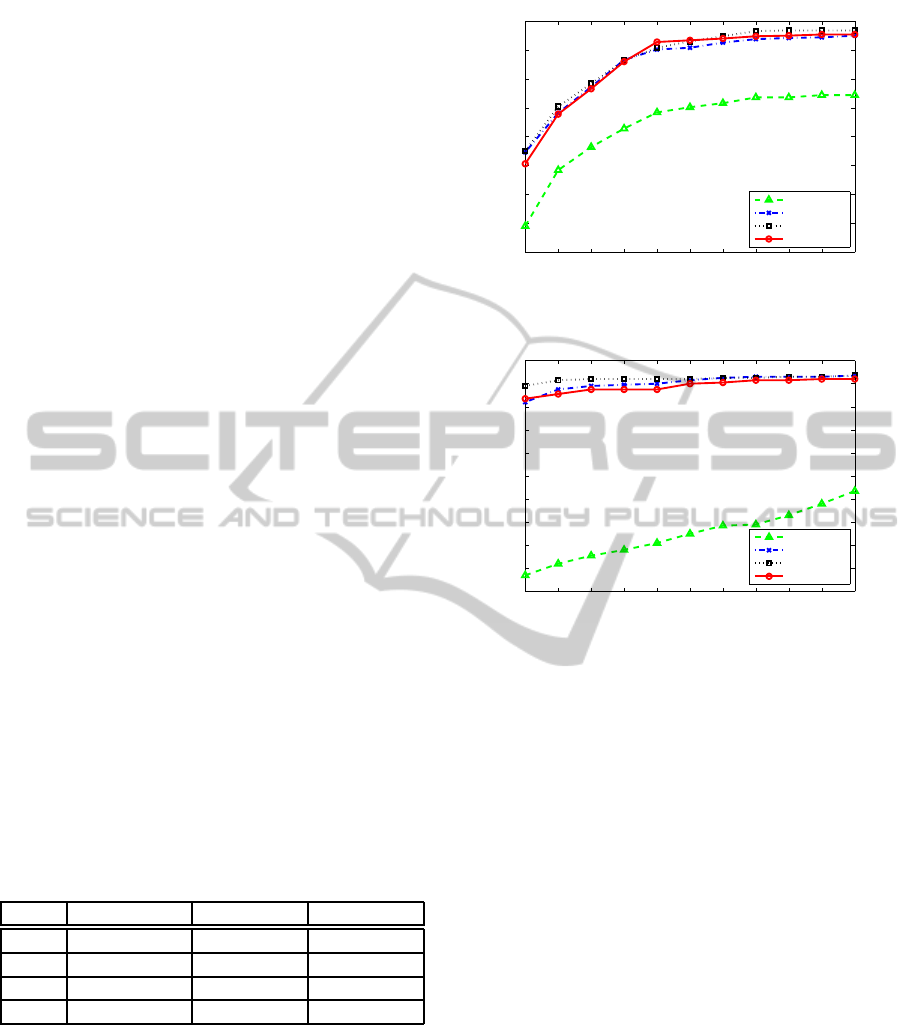
ations. In addition, Figure 4 and Figure 5 compare the
face pose estimation accuracy under different num-
ber of generations in PSO. One can observe that the
face alignment cannot achieve optimal solution with
small number of generations, like 10 generations, and
the performances with 20, 30, and 40 generations
are very similar, therefore, it can be concluded that
we can achieve considerable with 20 generations in
PSO. Though PSO with 40 generations gives slightly
smaller pose error, using 20 generations will save al-
most half of the processing time for one frame in real
time application.
Table 1: Face pose estimation error comparison with differ-
ent number of generations in PSO. Mean error and standard
deviation of nose tip location and face orientation (yaw and
pitch) are shown.
Itr(#) Nose(mm) Yaw(
◦
) Pitch(
◦
)
10 5.16± 11.69 2.19± 4.89 1.20± 2.32
20 3.51± 3.83 1.33± 2.12 0.67 ± 0.88
30 3.32± 3.83 1.16± 1.83 0.56 ± 0.76
40 3.26± 3.29 1.12± 2.03 0.53 ± 1.17
The performance of the proposed algorithm is
compared with other related work on the same
database in Table 2. It can be seen that the proposed
approach performs much better in both pose estima-
tion error (the first three columns) and estimation ac-
curacy (the last column) within 10
◦
face orientation
error than the latest work. Note that the errors re-
ported in (Breitenstein et al., 2008) are computed with
a threshold for a true positive rate of 80% and false
positive rate of 3% (i.e. a high confidence for nose
10 12 14 16 18 20 22 24 26 28 30
96
96.5
97
97.5
98
98.5
99
99.5
100
Nose error threshold (mm)
Accuracy (%)
10 generations
20 generations
30 generations
40 generations
Figure 4: Accuracy of nose tip localization with different
number of generations in PSO.
10 12 14 16 18 20 22 24 26 28 30
98
98.2
98.4
98.6
98.8
99
99.2
99.4
99.6
99.8
100
Angle error threshold (degrees)
Accuracy (%)
10 generations
20 generations
30 generations
40 generations
Figure 5: Accuracy of face orientation computation with
different number of generations in PSO.
identification). In the system of (Fanelli et al., 2011a),
6.5% of the range images in ETH database were dis-
carded before computing the errors, because these im-
ages failed to be estimated. In a word, more or less
images were omitted when calculating the pose errors
in the two literatures mentioned above. However, the
pose estimation error in our work is calculated from
all frames in the whole database except for the first
frame in each sequence, which is taken as the tem-
plate. Therefore, one can conclude that the proposed
approach can handle more difficult situations and es-
timate face pose more accurately than the compared
work in Table 2.
Furthermore, as shown in Table 3, the proposed
approach renders higher face pose estimation accu-
racy than (Breitenstein et al., 2008) and (Fanelli et al.,
2011a) within angle error thresholds of 10
◦
, 15
◦
, and
20
◦
. The accuracy of the proposed approach within
the most conservative threshold 10
◦
is even higher
than that of the other two within the less conservative
threshold 20
◦
.
Finally, some correctly estimated face depth im-
ages by the proposed approach from the ETH Face
Pose Range Image Data Set (Breitenstein et al., 2008)
were sampled to further prove its efficiency. As
AnImprovedApproachforDepthDatabasedFacePoseEstimationusingParticleSwarmOptimization
539
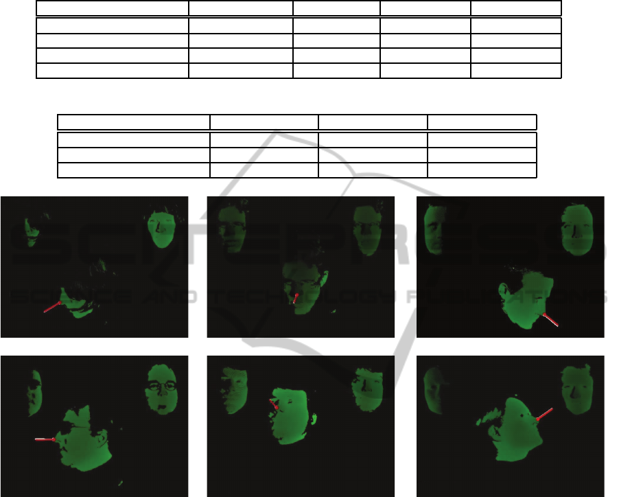
Table 2: Face pose estimation comparison using the ETH Face Pose Range Image Data Set (Breitenstein et al., 2008). The
first three columns show mean error and standard deviation for nose tip localization and face orientation estimation (Yaw,
Pitch). The last column shows the percentage of successfully estimated frames for the predefined angle error threshold of 10
◦
.
Nose error (mm) Yaw error (
◦
) Pitch error (
◦
) Accuracy (%)
(Breitenstein et al., 2008) 9.00± 14.00 6.10± 10.30 4.20± 3.90 80.8
(Fanelli et al., 2011a) 13.40± 21.10 5.70± 15.20 5.10± 4.90 90.4
(Padeleris et al., 2012) 7.05± 6.46 1.62± 1.59 2.05± 1.87 90.1
Proposed Approach 3.26± 3.29 1.12± 2.03 0.53± 1.17 99.7
Table 3: Face pose estimation accuracy comparison with different angle error thresholds.
10
◦
accuracy (%) 15
◦
accuracy (%) 20
◦
accuracy (%)
(Breitenstein et al., 2008) 80.8 97.8 98.4
(Fanelli et al., 2011a) 90.4 95.4 95.9
Proposed Approach 99.7 99.7 99.8
(a) (b) (c)
(d) (e) (f)
Figure 6: Some face pose estimation results from the ETH Face Pose Range Image Data Set (Breitenstein et al., 2008) with the
proposed approach. In each image (a)-(f): The person-specific template face is shown in top right; The optimal transformed
face is shown in top left; Dot represents nose tip location; Face direction is illustrated by a straight line originated from nose
tip and paralleled to face direction vector. (Red: estimated pose; White: ground truth).
shown in Figure 6, one can see that the proposed al-
gorithm can give high pose estimation accuracy for
the situations of both large pose variation and partial
occlusion (e.g. long hairs (a) and wearing glasses (b),
(d)).
4 CONCLUSIONS
In conclusion, an improved algorithm for face pose
estimation based on 3D data have been presented in
detail in this paper. The contributions of this work in-
clude: 1) The proposed approach, which has no need
of surface reconstruction and depth image resam-
pling, improves the accuracy and computing speed
for 3D face pose estimation. Comparing to the lat-
est work of others, the proposed approach demon-
strates the best performance in the public database;
2) A new hybrid method for nose tip localization has
been proposed, and its efficiency and reliability have
been proved by experimental results.
To further improve the proposed approach, in the
future work, a genetic face model will be built to get
rid of the initialization part and GPU programming
will be studied to implement the proposed approach
in real time.
VISAPP2014-InternationalConferenceonComputerVisionTheoryandApplications
540

REFERENCES
Back, T. (1996). Evolutionary algorithms in theory and
practice: evolution strategies, evolutionary program-
ming, genetic algorithms. Oxford University Press,
USA.
Besl, P. and McKay, N. (1992). A method for registration
of 3d shapes. IEEE Transactions on pattern analysis
and machine intelligence, 14(2):239–256.
Bleiweiss, A. and Werman, M. (2010). Robust head pose
estimation by fusing time-of-flight depth and color. In
Proceedings of IEEE International Workshop on Mul-
timedia Signal Processing, pages 116–121.
Breitenstein, M., Kuettel, D., Weise, T., Gool, L. V., and
Pfister, H. (2008). Real-time face pose estimation
from single range images. In Proceedings of IEEE
Conference on Computer Vision and Pattern Recogni-
tion, pages 1–8.
Cai, Q., Gallup, D., Zhang, C., and Zhang, Z. (2010). 3d de-
formable face tracking with a commodity depth cam-
era. In Proceedings of European Conference on Com-
puter Vision, pages 229–242.
Fanelli, G., Gall, J., and Gool, L. V. (2011a). Real time head
pose estimation with random regression forests. In
Proceedings of IEEE Conference on Computer Vision
and Pattern Recognition, pages 617–624.
Fanelli, G., Weise, T., Gall, J., and Gool, L. V. (2011b).
Real time head pose estimation from consumer depth
cameras. Pattern Recognition, pages 101–110.
Ghorbel, M. B., Baklouti, M., and Couvet, S. (2010). 3d
head pose estimation and tracking using particle fil-
tering and icp algorithm. Articulated Motion and De-
formable Objects, pages 224–237.
Horn, B. and Harris, J. (1991). Rigid body motion from
range image sequences. CVGIP: Image Understand-
ing, 53(1):1–13.
Kondori, F., Yousefi, S., Li, H., and Sonning, S. (2011). 3d
head pose estimation using the kinect. In Proceedings
of International Conference on Wireless Communica-
tions and Signal Processing, pages 1–4.
Mora, K. F. and Odobez, J. (2012). Gaze estimation from
multimodal kinect data. In Proceedings of IEEE Com-
puter Society Conference on Computer Vision and
Pattern Recognition Workshops, pages 25–30.
Murphy-Chutorian, E. and Trivedi, M. (2009). Head pose
estimation in computer vision: A survey. IEEE Trans-
actions on Pattern Analysis and Machine Intelligence,
31(4):607–626.
Padeleris, P., Zabulis, X., and Argyros, A. (2012). Head
pose estimation on depth data based on particle swarm
optimization. In Proceedings of IEEE Computer So-
ciety Conference on Computer Vision and Pattern
Recognition Workshops, pages 42–49.
Rajwade, A. and Levine, M. (2006). Facial pose from 3d
data. Image and Vision Computing, 24(8):849–856.
Seemann, E., Nickel, K., and Stiefelhagen, R. (2004). Head
pose estimation using stereo vision for human-robot
interaction. In Proceedings of IEEE International
Conference on Automatic Face and Gesture Recogni-
tion, pages 626–631.
Tang, Y., Sun, Z., and Tan, T. (2011a). Face pose estima-
tion based on integral slice features of single depth im-
ages. In Proceedings of Asian Conference on Pattern
Recognition, pages 530–534.
Tang, Y., Sun, Z., and Tan, T. (2011b). Real-time head pose
estimation using random regression forests. Biometric
Recognition, pages 66–73.
Tu, Y., Zeng, C., Yeh, C., Huang, S., Cheng, T., and Ouhy-
oung, M. (2011). Real-time head pose estimation us-
ing depth map for avatar control. In Proceedings of
IPPR Conference on Computer Vision, Graphics, and
Image Processing.
Wang, H. and Ying, Y. (2012). A novel torchlight data as-
sociation strategy for surface registration. In Proceed-
ings of IEEE/RSJ International Conference on Intelli-
gent Robots and Systems, pages 1708–1713.
Weise, T., Leibe, B., and Gool, L. V. (2007). Fast 3d scan-
ning with automatic motion compensation. In Pro-
ceedings of IEEE Conference on Computer Vision and
Pattern Recognition, pages 1–8.
Zhang, Z., Liu, Z., Adler, D., Cohen, M., Hanson, E., and
Shan, Y. (2004). Robust and rapid generation of ani-
mated faces from video images: A model-based mod-
eling approach. International Journal of Computer
Vision, 58(2):93–119.
AnImprovedApproachforDepthDatabasedFacePoseEstimationusingParticleSwarmOptimization
541
