
Improving NS-2 Network Simulator to Evaluate
IEEE 802.15.4 Wireless Networks Under Error Conditions
Andr´e Guerreiro, Jeferson L. R. Souza and Jos´e Rufino
University of Lisbon - Faculty of Sciences, Large-Scale Informatics System Lab. (LaSIGE), Lisbon, Portugal
Keywords:
NS-2 Simulator, Wireless Communications, Network Inaccessibility, Timeliness, Dependability.
Abstract:
The behaviour of wireless networks in the presence of error conditions is still being studied by the research
community. Improvements on the evaluation methods and tools are crucial to acquire a better knowledge,
and understanding of the network operation under such conditions. This paper presents enhancements on the
network simulator NS-2 to support the evaluation of the IEEE 802.15.4 standard, used as a case study. We
are specially interested to evaluate the temporal behaviour of the network operation under errors conditions,
considering the applicability of the IEEE 802.15.4 standard in safety-critical environments such as industrial
and vehicular.
1 INTRODUCTION
The applicability of wireless technologies on envi-
ronments with temporal restrictions has been attract-
ing interest of the real-time research community in
the last decade (
˚
Akerberg et al., 2011; Stone et al.,
2012). The main advantages offered by wireless net-
works are: the reduction of size, weight, and power
(SWaP) consumption; the ability to have mobile enti-
ties; and the possibility to establish networking com-
munications where the use of wires is extremely dif-
ficult or impractical (Kandhalu and Rajkumar, 2012).
There are many studies in wireless communica-
tions addressing the temporal behaviour of commu-
nication services at the lowest level of the protocol
stack (Han et al., 2011; Shuai and Zhang, 2010; Hou
and Bergmann, 2010). These studies pay little or no
attention to the dependability aspects of medium ac-
cess control (MAC) sublayer and its services, which
are essential to assure the timeliness and resilience of
the network when operating under error conditions.
This paper evaluate the network simulator NS-2
to identify its limitations, proposing enhancements
to provide a better knowledge and understanding of
wireless network operation under such conditions.
The NS-2 was chosen due to their native support to
simulate wireless networks based on IEEE 802.15.4
standard, which is used as case study.
Our research achievements are organised as fol-
lows: Section 2 describes our system model, which
comprises the assumptions utilised through the pa-
per; Section 3 presents a brief overview of the IEEE
802.15.4 standard; Section 4 addresses the main tem-
poral issues of the network operation under error con-
ditions; Section 5 presents a brief overview of the
NS-2 simulator, including its limitations; Section 6
presents the improvements in the IEEE 802.15.4 NS-
2 module, including a fault injector that complements
the existent NS-2 mechanisms, and a new component
to perform the temporal analysis of the network oper-
ation; Section 7 presents the simulation setup of the
Inaccessibility Scenarios and a simulation script de-
scription; Section 8 presents the results obtained in
the simulation of IEEE 802.15.4 networks, allowing
an enhanced temporal evaluation of such networks;
Finally, Section 9 presents some conclusions and fu-
ture directions of this work.
2 SYSTEM MODEL
Our system model is formed by a set of wireless
nodes
1
X = {x
1
,x
2
,...,x
n
}, being 1 < n ≤ #A, where
A is the set of all wireless nodes using the same com-
munication channel. The set X itself represents a net-
work entity dubbed wireless network segment (WnS),
as depicted in Figure 1. A WnS establishes a wire-
less network where each node can sense one another
within one-hop of distance, being more complex net-
1
A wireless node is a networked device capable to commu-
nicate with other nodes
213
Guerreiro A., L. R. Souza J. and Rufino J..
Improving NS-2 Network Simulator to Evaluate IEEE 802.15.4 Wireless Networks Under Error Conditions.
DOI: 10.5220/0004734102130220
In Proceedings of the 3rd International Conference on Sensor Networks (SENSORNETS-2014), pages 213-220
ISBN: 978-989-758-001-7
Copyright
c
2014 SCITEPRESS (Science and Technology Publications, Lda.)

Figure 1: The graphical representation of a wireless net-
work segment.
works composed by more than one WnS. For simplifi-
cation purposes, our analyses assume a network with
one WnS, being its behaviour supported by the fol-
lowing assumptions:
1. The communication range of X, i.e. its broadcast
domain, is given by: B
X
=
n
T
j=1
B
D
(x), ∀x ∈ X,
where B
D
(x) represents the communication range
of a node x;
2. ∀x ∈ A, x ∈ X ⇐⇒ B
D
(x)
T
B
X
= B
X
or, as
a consequence of node mobility, x /∈ X ⇐⇒
B
D
(x)
T
B
X
6= B
X
;
3. ∀x ∈ X can sense the transmissions of one another;
4. ∃x ∈ X which is the coordinator, being unique and
with responsibility to manage the set;
5. A network component (e.g. a node x ∈ X) ei-
ther behaves correctly or crashes upon exceed-
ing a given number of consecutive omissions (the
component’s omission degree, f
o
) in a time inter-
val of reference
2
, T
rd
;
6. failure bursts never affect more than f
o
transmis-
sions in a time interval of reference, T
rd
;
7. omission failures may be inconsistent (i.e., not ob-
served by all recipients).
For a given WnS, assumptions 1, 2, and 3 define
the physical relationship between nodes, assumption
4 defines the existence of a coordinator, and assump-
tions 5, 6, and 7 define how the occurrence of com-
munication errors are modelled and handled within
the WnS. All communications and relations between
2
For instance, the duration of a given protocol execution.
Note that this assumption is concerned with the total num-
ber of failures of possibly different nodes.
Figure 2: Superframe structure (Standard and Society,
2011) .
nodes are established at MAC level, which are rein-
forced by assumption 3. As a consequence of mobil-
ity, nodes may be driven away of a given WnS (as-
sumption 2). All communication errors within WnS
are transformed into omissions (assumption 5), and in
the context of network components an omission is an
error that destroys a data or control frame.
3 IEEE 802.15.4 OVERVIEW
IEEE 802.15.4 is a standard for wireless sensor and
actuator networks (WSANs), which support two op-
erating modes: beacon-enabled and non beacon-
enabled. In this paper we only address the beacon-
enabled mode, which supports traffic with temporal
restrictions. The network coordinator controls the
network access through the superframe structure de-
picted in Figure 2.
This superframe structure comprises an active pe-
riod, and optionally, an inactive period. In the ac-
tive period there are a contention access period (CAP)
and a contention free period (CFP). CAP is used to
transmit traffic without any temporal guarantee and
in a best effort approach. In CFP nodes can allo-
cate time slots to transmit traffic with temporal restric-
tions (i.e., time division multiple access (TDMA) ap-
proach), where such slots are dubbed guarantee time
slots (GTSs). The inactive period is used for power
saving purposes (when needed).
As depicted in Figure 2, the duration of CAP and
CFP are defined by two parameters: the beacon or-
der (BO); and the superframe order (SO). The value
of BO defines the superframe duration (i.e., the bea-
con interval, T
BI
), and the value of SO the duration
of the active period (CAP+CFP). The duration of the
beacon interval is T
BI
= T
BSD
.2
BO
, where T
BSD
is the
base value of T
BI
when BO = 0, as defined within
the IEEE 802.15.4 standard. The real length of CFP
depends on the number of GTSs actually allocated.
There is no inactive period when BO = SO, being the
duration of the active period equal to T
BI
.
SENSORNETS2014-InternationalConferenceonSensorNetworks
214

Table 1: Easy-to-use formulas defining the durations of periods of network inaccessibility .
Scenario Equation
Single Beacon Frame Loss T
wc
ina←sb fl
= T
BSD
. (2
BO
+ 1)
Multiple Beacon Frame Loss T
wc
ina←mb fl
= T
BSD
.
2
BO
+ 1
. nrLost
Synchronisation Loss T
ina←nosync
= T
BSD
.
2
BO
+ 1
. nrLost
Orphan Node T
wc
ina←orphan
= T
ina←nosync
+ T
MLA
(Orphan) +
nrchannels
∑
j=1
T
wc
MAC
(Orphan) + nrWait . T
BSD
+ T
wc
MAC
ack
(Realign)
Coordinating Realignment T
wc
ina←realign
= T
MLA
(Realign) + T
wc
MAC
ack
(Realign)
Coordinator Conflict Detection T
wc
ina←C
Detection
= T
wc
MAC
ack
(C
Conflict)
Coordinator Conflict Resolution T
wc
ina←C
Resolution
= T
MLA
(Conflict) +
nrchannels
∑
j=1
T
wc
MAC
(Beacon
R)+nrWait.T
BSD
+ T
MLA
(Realign) + T
wc
MAC
(Realign)
Extract Request T
wc
ina←extReq
= T
wc
MAC
ack
(ExtReq) +T
wait
GTS request T
wc
ina←GTS
= T
wc
MAC
ack
(GTS)
Association T
wc
ina←assoc
=
nrchannels
∑
j=1
T
wc
MAC
(Beacon
R) + nrWait.T
BSD
+ T
MLA
(Beacon)+ T
wc
ina←extReq
+ T
MLA
(AssocReq) + T
wc
MAC
ack
(AssocReq)
Re-Association T
wc
ina←reAssoc
= T
ina←nosync
+ T
wc
ina←assoc
4 CHARACTERISING IEEE
802.15.4 NETWORK
OPERATION UNDER ERROR
CONDITIONS
The utilisation of IEEE 802.15.4 WSANs is emerg-
ing in environments such as industrial and vehicu-
lar, where some networking communications must re-
spect restrict temporal constrains. Wireless communi-
cations may be affected by different sources of inter-
ferences, such as electromagnetic waves, obstacles on
the communication path, or even by the mobility of
nodes. Communication errors may occur as a conse-
quence of such interferences, disturbing the commu-
nication services and the network operation itself.
The occurrence of such communication errors
may affect two different types of operations, which
are related to transmit data traffic and to control
and maintain the network operation. The literature
presents different works (Wang et al., 2012; Saifullah
et al., 2011), which are only focused on the character-
isation and presence of errors on data transmissions,
disregarding the negative effects of such conditions in
the MAC management operations.
In the contextof MAC managementoperations, an
already known severe consequence of communication
errors is dubbed network inaccessibility (Souza and
Rufino, 2009). A network inaccessibility period is
characterised by the occurrence of ”blackouts“ within
networking communications, where the network re-
mains inaccessible by a temporary period of time.
A research study performed by (Souza and Rufino,
2009) presents formulas to specify the duration of
network inaccessibility for the IEEE 802.15.4 stan-
dard. Those communication ”blackouts“ may have a
huge impact on the timeliness and dependability of
the whole networking system, where a better evalua-
tion may suggest the incompatibility of the guarantees
offered by the communication service, and the tempo-
ral requirements of the target environment.
In Table 1 we present a summary of the worst case
duration (represented by the superscript (
wc
)) for each
network inaccessibility scenario. As an example, we
will briefly explain the characterisation of the most
evident network inaccessibility scenarios, which are
related with the loss of beacon frames. Three different
inaccessibility scenarios may occur if such frames are
not received correctly.
A single beacon frame loss
occurs when only one
beacon is lost. The duration of such scenario is equal
to T
BI
+ T
BSD
, where T
BSD
is utilised as a tempo-
ral compensation to accommodate possible clock de-
viations between network nodes. The loss of mul-
tiple and consecutive beacons characterises the oc-
currence of the multiple beacon frame loss scenario
,
where a correct beacon is received after the loss of the
previous nrLost beacons. The synchronisation loss
is a special case of the multiple beacon frame loss
scenario where after the loss of nrLost beacons the
next beacon is also lost. The duration of both
multiple beacon frame loss
and synchronisation loss
is a multiple of the single beacon frame loss, which
is nrLost .(T
BI
+ T
BSD
). For simplification purposes
we replace the (T
BSD
.2
BO
) by T
BI
, as indicated in sec-
tion 3. The complete network inaccessibility charac-
terisation for the IEEE 802.15.4 is present in (Souza
and Rufino, 2009).
5 NS-2 SIMULATOR OVERVIEW
The NS-2 is a discrete-event simulation tool, widely
ImprovingNS-2NetworkSimulatortoEvaluateIEEE802.15.4WirelessNetworksUnderErrorConditions
215
used to study the dynamics of communication net-
works. It is developed in a collaborative effort by
many institutions, containing contributions from dif-
ferent researchers.The simulation library and network
protocols are written using the C and C++ languages.
The simulation environment is described and modi-
fied using the OTcl script language, without the ne-
cessity to recompile the whole NS-2 source code.
Every action in NS-2 is associated with events
rather than time. An event comprises an execution
time, a set of tasks, and a reference to the next event.
These events are connected to each other, and form a
chain of events on the simulation time line. The se-
quential execution of this chain of events is controlled
and managed by a scheduler component, the brain and
execution engine of the NS-2. It is possible to define
its own procedures and variables to facilitate the inter-
action. The member procedures and variables in the
OTcl domain are called instance procedures.
The IEEE 802.15.4 NS-2 module is provided in
the form of methods of each layer specified in the
IEEE 802.15.4 standard. The module came with dif-
ferent functionalities, and support different network
topologies (star and point-to-point), two types of op-
eration (beacon and non-beacon enabled), and ba-
sic MAC management actions such as Association,
Channel Scan, energy model, etc.
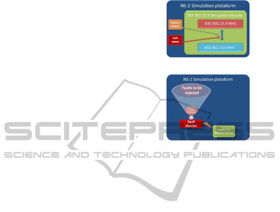
6 ENHANCING NS-2 SIMULATOR
The evaluation of the network operation under error
conditions needs components capable to inject faults
in the simulation, which cause the network inacces-
sibility scenarios described previously. The NS-2 al-
ready provides components to perform such fault in-
jection, but these components using an error model
not capable to affect specific MAC frames, utilised by
the IEEE 802.15.4 to control the access to the net-
work.
To overcame the current error model limitation,
we complement the existing NS-2 components with
a new fault injector component, which is capable to
generate faults in specific MAC frames. We also in-
corporate in NS-2 a a temporal analysis component,
which is needed to account and measure the effects
of faults generated by the fault injector component.
These two components are independent of the type
of network, being separated from the IEEE 802.15.4
module, as represented in the figure 3.
6.1 Fault Injector Component
Our fault injector is capable to use a fault pattern to
Figure 3: New Features in 802.15.4 module.
Figure 4: Fault Injector scheme.
inject errors during the simulation. The criteria to de-
fine the fault pattern is totally configurable, allowing
the definition of deterministic or probabilistic fault
patterns. An illustration of the fault injection scheme
is shown in the figure 4.
A fault pattern can be defined to generate trans-
mission errors randomly in time (random noise or in-
terference) or be localized in specific time intervals
(deterministic noise). On both of these patterns, the
fault injector can be customized regarding the type of
frame to affect, the rate and the duration of the fault
injection.
Patterns with long duration are discouraged for
deterministic error models, since such long duration
may cause a permanent inaccessibility to the network
access. For example, if we are corrupting a beacon
frame injecting deterministic faults successively over
a long period we may cause the loss of synchroniza-
tion by the node and consequently this becoming un-
able to access the network again. However this type
of pattern is beyond the scope of this work that is to
analyse accidental faults where such pattern does not
happen.
To perform the random noise or interference is
possible to simulate aleatory errors on the network
communication, injecting faults between the MAC
and the PHY. A random function implemented in
the fault injector allows inserting random corrup-
tion events in the NS-2 scheduler as described in
Algorithm:1. In case of random noise the instant
when the corruption occurs is totally aleatory, and is
generated through a seed given by argument as de-
SENSORNETS2014-InternationalConferenceonSensorNetworks
216

Algorithm 1: Fault Injector - A random function.
1: Begin.
2: randomTime ← randomGenerator(seed);
3: NewRandomEvent ← faultInjector(frameToCorrupt);
4: Scheduler.schedule(NewRandomEvent,randomTime);
5: CorruptNode.Update();
6: End.
scribed in line 2. A new eventis created and the action
associated with it is a frame corruption performed by
the fault injector as indicated in line 3. Finally the
NewRandomEvent which will perform the corruption
is inserted in the NS-2 scheduler and executed at the
defined instant as in line 4. An information about the
corruption occurred in a specific node is recorded as
described in line 5.
The fault injector achieves the frame corruption
as described in Algorithm:2, accessing the command
header of the frame as represented in line 5, and
changing a bit in the frame content, implying the drop
of these frames in the MAC level of the receiving
nodes. When the frame is received if the fault in-
jector is active, we can decide if a specific frame is
affected or any frame that a node receives will be
corrupted. The parameter frameToCorrupt repre-
sented on line 3 is previously defined and if desired
all the received frames can be affected defining the
frameToCorrupt to a specific value. An informa-
tion about the corruption occurred in a specific node
is recorded as described in line 6. This information
is used for a better control of the simulation events.
The fault injection may be performed in the coordi-
nator, which implies, depending on the type of frame
affected, that the whole network may be inaccessible,
in the specific case of affecting a MAC control frame.
In case we decide to affect a MAC control frame, af-
fecting specific network points, the fault injection can
be performed for example at non-coordinator nodes
tracking the reception of beacon frames. In the spe-
cific case, when we perform corruption in a MAC
control frame such as the beacon in the coordinator,
none of the nodes receives the beacon and therefore
the whole network will be inaccessible. Otherwise,
when the corruption is performed in the nodes that
should receive beacon frames, only the node that has
the fault injector component activated, i.e. beacon
corruptions occurring, cannot access the medium and
becomes inaccessible. The corruption of the frames
can be disabled, through the deactivation of the fault
injector on the tcl script, and the normal behaviour of
the network restored at any time.
6.2 Temporal Analysis Component
The temporal analysis component was designed to
Algorithm 2: Fault Injector Mechanism.
1: Begin.
2: MAC.Receive( f rame);
3: if f rame = frameToCorrupt then
4: for selected Fault Pattern do
5: CommandHeader( frame)− > error() = 1;
6: CorruptNode.Update();
7: end for
8: end if
9: End.
measure the temporal aspects of received frames,
from their duration to the effects of frames received
with errors during the network operation. In this pa-
per, we instrumented the temporal analysis compo-
nent to measure network inaccessibility events. As
the occurrence of network inaccessibility is related
with the MAC control frames (e.g., beacons), this
component was configured to monitor and capture in-
formation about such kind of frames.
Let us present an example to characterise how the
temporal analysis component works. We use the bea-
con frame as the frame to be monitored in such exam-
ple. When the received beacon is corrupted, the tem-
poral analysis component starts a timer to account the
related network inaccessibility period. When a new
beacon is received successfully, the timer is stopped
and the duration of such period is registered.
When the simulation is finished, the temporal
analysis component generates a report, regarding all
events captured during the simulation. The report is
utilised as input to a gnuplot script, which transform
the raw data within the report to a graphical represen-
tation of the captured events.
7 SIMULATING
INACCESSIBILITY
SCENARIOS
The simulation is defined in an OTcl script (Listing:1)
and is carried out in an one-hop star topology, where
all the nodes are within the range of each other.
In the script (Listing:1) we define that the first
node to start was the coordinator, specifying the val-
ues of its BO and SO in line 1. After the WnS is es-
tablished we start the nodes in line 2. Our temporal
analysis component is enabled on line 3, given the se-
lected scenario. The periodic beacon transmission is
initiated at the coordinator on line 4, taking the BO
and SO as arguments. At line 5 we enable the GTS
transmission for the node(1), which means that each
time this node have data to transmit will use the GTS
mechanism. Finally, at line 6 we start our fault injec-
ImprovingNS-2NetworkSimulatortoEvaluateIEEE802.15.4WirelessNetworksUnderErrorConditions
217

tor to, in this example, corrupt beacon frames for a
certain number of rounds.
1 Event at 0 .0 node (0)
st a rtW nSCoor dinat or $beaconOrder
$superFrameOrder ” ;
2 Event at 20 .0 node ( 1 ) & node ( 2)
s t a r t D e v i ce ”
3 Event at 20 .0 node ( 1 )
enableTemporalAccount $Scenario ”
;
4 Event at 30 .0 node ( 0 )
st a rtBeaconTran sm i s si on
$beaconOrder $superFrameOrder ”
5 Event at 30 .0 node ( 1 ) GTS On”
6 Event at 30 .0 node ( 1 ) S t a r t F aul t
I n j e c t i o n $Beacon $Rounds ”
7 Event at $stopTime ” st op ”
Listing 1: Example of NS-2 Simulation Script.
To simulate a network operation under error con-
ditions, implying the occurrence of network inacces-
sibility, we configure our fault injector component to
generate deterministic faults. For each addressed sce-
nario we set our fault injector to corrupt a specific
frame at a given number of times, on a chosen node.
The fault injector can corrupt one of each frame type
present in the Table: 2.
To achieve the Single Beacon Frame Loss
(SBFL) scenario we executed the following schedule
of Events:
1 Event at 30 .0 node ( 1 ) S t a r t F aul t
I n j e c t i o n $Beacon $SBFL”
In this scenario the beacon frame will be corrupted
SBFL number of times (i.e., only one time) at the
Node(1), after 30 simulation seconds.
The Multiple Beacon Frame Loss (MBFL)
occurs when we change the number of corrupting
rounds on the fault injector depending on the value
that MBFL assumes in order to achieve the loss
of nrLost beacons. The synchronization loss is
a special case of the MBFL scenario where after
the loss of nrLost beacons the next beacon is also lost.
1 Event at 30 .0 node ( 1 ) S t a r t F aul t
I n j e c t i o n $Beacon $MBFL”
The Orphan notification and Coordinator
realignment are achieved when the fault injector
corrupts NOSYNC beacon frames, corresponding to
the current scenario, and the node lose the synchro-
nization. The Orphan notification is observed on the
node and the Coordinator realignment is transmitted
by the coordinator on response.
Table 2: MAC frame types.
Frame type value Command frame ID Standard Reference
0 Beacon
1 Data
2 Ack
3 MAC Control Frame
01 Association Request
02 Association Response
03 Disassociation
04 Data Request
05 Coordinator conflict
06 Orphan
07 Beacon request
08 Coordinator realignment
09 GTS request
1 Event at 30 .0 node ( 1 ) S t a r t F aul t
I n j e c t i o n $Beacon $NOSYNC”
So that Coordinator Conflict Detection can oc-
cur, this event has to be forced on the simulator. Once
every time a node becomes a coordinator it assumes
its ID as the networkID, so a coordinator conflict is
impossible because every coordinator assumes a dis-
tinct ID. To force that event we oblige the coordinator
to use the same identifier with the following line.
1 Event at 0 . 0 node (1) Coord inator
Co nf li ct 1”
2 Event at 0 . 0 node (0) Coord inator
Co nf li ct 1”
When the GTS mechanism is previously acti-
vated from the script, and the node has data to trans-
mit, a GTS Request will occur. This request will be
send to the coordinator by the node to perform an allo-
cation of a GTS slot for exclusive transmission time.
1 Event at 30 .0 node ( 1 ) GTS On”
8 RESULTS
8.1 Simulation Setup
The network was simulated with seven nodes, where
one of these nodes, in the center, was the coordinator.
All other nodes are in the radio transmission range
of the coordinator, and in the range of each other. A
BO = 3 was utilised to specify the superframe dura-
tion within simulations.
The characteristics of the simulation setup sce-
nario are shown in Table 3. To evaluate the network
behaviour under error conditions we applied different
SENSORNETS2014-InternationalConferenceonSensorNetworks
218
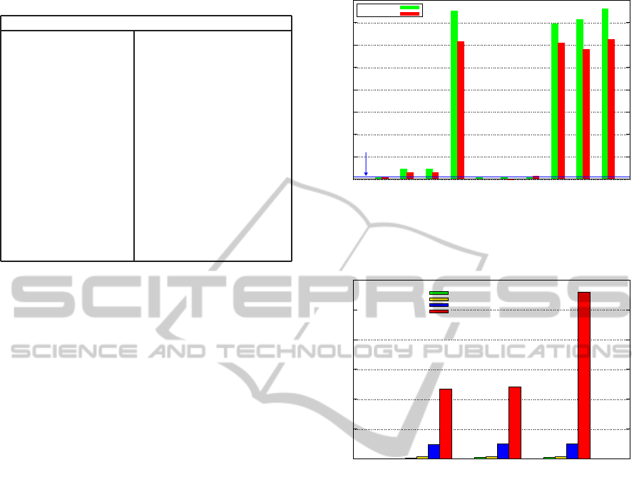
Table 3: Simulation Parameters.
Simulation Parameters
NS-2 Version 2.35 updated with GTS, Fault Injector,
and Temporal Analysis features
Network Topology Star Topology
Nodes 7
Traffic Constant Bit Rate (CBR)
Reception range 15m
Carrier Sense range 15m
Packet Size 8, 67, 127 kbytes
CAP Transmission Type Direct, using CSMA/CA
CFP Transmission Type GTS transmission
Transmission/Reception Power 30mW
Beacon Enabled
Beacon Order 3
Superframe Order 3
Maximum CSMA/CA Attempts 4
Simulation Time 600 seconds
error patterns on the simulation through fault injec-
tion.
The fault injection can be performed using three
different durations: short, medium, or long. The short
had the duration of a normal frame transmission, the
medium had the duration of the transmission of 3
frames, and the long had the duration of half a bea-
con.
The traffic generator is set to produce Constant
Bit Rate traffic (CBR), which means data frames are
transmitted at a constant rate from the nodes to the
coordinator. The payload of the sent data was also
varied, being the smallest payload of 8 kilobytes, the
medium of 67 kilobytes, and the large of 127 kilo-
bytes. The characteristics of the simulation scenario
are shown in Table 3.
8.2 Simulation Results
After the environment setup, the simulation was per-
formed to obtain the best and worst case duration of
the inaccessibility scenarios.
Figure 5 shows the graphic that represents the du-
ration of each network inaccessibility scenario, com-
paring the results of the previous theoretical study
in (Souza and Rufino, 2009) and the obtained simula-
tion results. The results presented in Figure 5 clearly
shows that periods of inaccessibility may have a huge
duration, which represents a non-negligible impact
for networks with temporal restricted traffic.
In the Figure 6 we can observe the Packet Error
Rate (PER) between different error conditions. As
expected, longer periods of fault injections implies a
higher PER. In comparison with the Control frame,
a frame that was transmitted without errors, we can
see an increasing PER related to the higher periods of
fault injection.
0
10
20
30
40
50
60
70
80
Single
beacon
frame loss
Multiple
beacon
frame loss
Synchonisation
loss
Orphan Coordinator
realignment
GTS
Request
Coordinator
Conflict
Detection
Coordinator
Conflict
Resolution
Association Re-
Association
Normalised duration (T
BI
times)
Network inaccessibility scenarios (BO=3)
Beacon interval (T
BI
)
Theoretical
Simulated
Figure 5: Normalized Inaccessibility Scenarios comparison
between Theoretical and Simulated worst case (BO=SO=3
and T
BI
= 0.123s).
0
2
4
6
8
10
12
8 67 127
Packet Error Rate (PER) (%)
Payload length (Bytes)
Fault Injection duration:
Control
Short
Medium
Long
Figure 6: Packet Error Rate comparison between different
error patterns.
The result with the greatest impact is related with
the bigger payload, achieves a PER of more than 10%.
An important result of this study is that the influ-
ence of network errors, causing periods of inacces-
sibility in the network, cannot be overlooked if pre-
dictability and real-time operation is a system require-
ment, under the risk of jeopardize the safety and time-
liness of the entire system. The effects of network
inaccessibility incidents should be controlled by the
definition of strategies for the reduction of the peri-
ods of inaccessibility, which is achieved in (Souza and
Rufino, 2013).
9 CONCLUSIONS AND FUTURE
DIRECTIONS
The paper addressed the behaviour of IEEE 802.15.4
networks in the presence of network errors, leading to
periods of network inaccessibility.
ImprovingNS-2NetworkSimulatortoEvaluateIEEE802.15.4WirelessNetworksUnderErrorConditions
219

Significant improvementsand modificationsin the
NS-2 simulator IEEE 802.15.4 module were pre-
sented, which includes the specification of two addi-
tional components capable to inject and measure the
effects of errors during the network operation. The
presence and use of these two component were es-
sential to perform the simulation and evaluation of all
network inaccessibility scenarios.
The results obtained by our simulations evidence
the relevant temporal aspects of the IEEE 802.15.4
beacon-enabled networks operating under error con-
ditions. Such results can be utilised in the specifica-
tion of a robust timeliness model of the network, in
order to achieve an effective support to real-time op-
eration in IEEE 802.15.4 networks.
ACKNOWLEDGEMENTS
This work was partially supported: by the
EC, through project IST-FP7-STREP-288195
(KARYON); by FCT/DAAD, through the transna-
tional cooperation project PROPHECY; and by
FCT, through the project PTDC/EEI-SCR/3200/2012
(READAPT), the Multiannual Funding Program, and
the Individual Doctoral Grant SFRH/BD/45270/2008.
REFERENCES
Han, S., Zhu, X., Mok, A., Chen, D., and Nixon, M. (2011).
Reliable and Real-Time Communication in Industrial
Wireless Mesh Networks. 2011 17th IEEE Real-Time
and Embedded Technology and Applications Sympo-
sium.
Hou, L. and Bergmann, N. (2010). System Requirements
for Industrial Wireless Sensor Networks The Univer-
sity of Queensland.
Kandhalu, A. and Rajkumar, R. (2012). Qos-based resource
allocation for next-generation spacecraft networks. In
IEEE 33rd Real-Time Systems Symposium (RTSS).
˚
Akerberg, J., Gidlund, M., and Bj¨orkman, M. (2011). Fu-
ture research challenges in wireless sensor and actu-
ator networks targeting industrial automation. In 9th
IEEE Internation Conference on Industrial Informat-
ics (INDIN).
Saifullah, A., Xu, Y., Lu, C., and Chen, Y. (2011). End-
to-end delay analysis for fixed priority scheduling in
wirelesshart networks. In 17th IEEE Real-Time and
Embedded Technology and Applications Symposium
(RTAS).
Shuai, X. and Zhang, Z. (2010). Research of Real-Time
Wireless Networks Control System MAC Protocol.
Journal of Networks.
Souza, J. L. R. and Rufino, J. (2009). Characterization of
inaccessibility in wireless networks - a case study on
IEEE 802.15.4 standard. In IFIP 3th International
Embedded System Simposium IESS.
Souza, J. L. R. and Rufino, J. (2013). Analysing and reduc-
ing network inaccessibility in IEEE 802.15.4 wireless
communications. In 38th IEEE Conference on Local
Computer Networks (LCN).
Standard, I. and Society, I. C. (2011). IEEE Standard for
Local and metropolitan area networks, Part 15 . 4
: Low-Rate Wireless Personal Area Networks ( LR-
WPANs ) IEEE Computer Society S ponsored by the.
Stone, T., Alena, R., Baldwin, J., and Wilson, P. (2012).
A viable COTS based wireless architecture for space-
craft avionics. In IEEE Aerospace Conference, pages
1–11.
Wang, J., Dong, W., Cao, Z., and Liu, Y. (2012). On the
delay performance analysis in a large-scale wireless
sensor network. In IEEE 33rdReal-Time Systems Sym-
posium (RTSS).
SENSORNETS2014-InternationalConferenceonSensorNetworks
220
