
Control of a PTZ Camera in a Hybrid Vision System
Franc¸ois Rameau, C
´
edric Demonceaux, D
´
esir
´
e Sidib
´
e and David Fofi
Universit
´
e de Bourgogne, Le2i UMR 6306 CNRS, 12 rue de la Fonderie, 71200 Le Creusot, France
Keywords:
Fisheye Camera, PTZ, Target Detection, Hybrid Vision System.
Abstract:
In this paper, we propose a new approach to steer a PTZ camera in the direction of a detected object visible
from another fixed camera equipped with a fisheye lens. This heterogeneous association of two cameras
having different characteristics is called a hybrid stereo-vision system. The presented method employs epipolar
geometry in a smart way in order to reduce the range of search of the desired region of interest. Furthermore,
we proposed a target recognition method designed to cope with the illumination problems, the distortion of the
omnidirectional image and the inherent dissimilarity of resolution and color responses between both cameras.
Experimental results with synthetic and real images show the robustness of the proposed method.
1 INTRODUCTION
Stereo-vision is one of the most explored topic in
computer vision. The traditional approach is based
on the use of two cameras of same nature mimicking
the binocular human vision system (Marr and Poggio,
1977). Using two similar cameras drastically sim-
plifies the steps of calibration and matching. How-
ever, in this paper we are dealing with a non standard
stereo-vision rig, composed of a fisheye camera asso-
ciated with a Pan-Tilt-Zoom (PTZ) camera. This kind
of layout mixing different types of camera is called a
hybrid vision system.
Omnidirectional cameras have the great advantage
to provide a wide field of view (up to 360
◦
), however
they often provide a limited and non-linear resolution.
Furthermore, the use of omnidirectional sensors leads
to a strong geometric distortion of the image, making
most of the usual image processing methods ineffi-
cient.
On the other hand, a Pan-Tilt-Zoom camera is a
zooming perspective camera which can be mechan-
ically oriented in multiple directions. Despite a re-
stricted field of view, the ability to steer the camera
in the desired direction allows to cover a large region
of the scene (up to 360
◦
in panoramic and 180
◦
in tilt
direction, depending on the manufacturer). The zoom
permits to obtain high resolution images of a specific
region of interest (ROI). So, the versatility offered by
those kind of camera is really appreciable for many
applications especially in the field of video surveil-
lance.
The couple composed of these two cameras com-
bines the advantages given by both of them, that is
to say a large field of view and an accurate vision
of a particular ROI with an adjustable level of de-
tails using the zoom. Nevertheless, the control of the
mechanical camera with information from the fisheye
one is not straightforward. Moreover, the difference
between the two cameras has to be taken into consid-
eration. In fact, the model of projection as well as the
color response and the resolution of the two sensors
are greatly different.
Therefore, in this paper we propose a new ap-
proach able to cope with the previously mentioned
problems and to find out the orientation of the PTZ
camera for visualizing a defined ROI on the fisheye
image.
The rest of the paper is organized as follows. First,
we review previous methods using heterogeneous vi-
sion system. Section 2 is dedicated to an overview of
the necessary background, containing a detailed de-
scription of the spherical model and of the epipolar
geometry. The sections 3 and 4 respectively deal with
the model of our system and its calibration. In Section
5, we describe our method of target detection through
an hybrid stereo-vision system. Section 6 summarizes
the results of our experiments. Section 7 concludes
the paper.
1.1 Previous Works
A hybrid vision system means that the two cameras
of the rig have different characteristics. This com-
397
Rameau F., Demonceaux C., Sidibé D. and Fofi D..
Control of a PTZ Camera in a Hybrid Vision System.
DOI: 10.5220/0004734703970405
In Proceedings of the 9th International Conference on Computer Vision Theory and Applications (VISAPP-2014), pages 397-405
ISBN: 978-989-758-009-3
Copyright
c
2014 SCITEPRESS (Science and Technology Publications, Lda.)

bination allows to obtain additional information such
as an extension of the field of view, the extraction of
3D information or the study of a wider range of wave-
lengths (Cyganek and Gruszczy
´
nski, 2013). Recently,
we noticed the emergence of composite stereo-vision
sensors using the association of an omnidirectional
and a perspective camera. This camera association
is often considered as a bio-inspired method since the
human retina can be divided into two parts - the foveal
and the peripheral (Gould et al., 2007) - leading to a
coarse vision in the peripheral region which is more
sensitive to motion and a fine vision in the central part
of the retina. In robotics, many articles have taken ad-
vantage of this specificity to facilitate the navigation
using the wide angle camera, while the perspective
camera allows to obtain accurate details of the envi-
ronment. It is for instance the case in (Neves et al.,
2008), where a soccer robot can navigate and detect
the ball using an omnidirectional camera while a per-
spective camera is used for an accurate front view of
the game. Similarly, in (Adorni et al., 2002) the au-
thors proposed another approach for obstacle avoid-
ance using merged information acquired from a PT
and a catadioptric camera. Some innovative robotic
applications using the previously described tandem of
cameras do exist such as the robot photographer pre-
sented in (Bazin et al., 2011). Furthermore the use
of this system is not only limited to ground robots
but it is also applied to UAVs, for instance in (Ey-
nard et al., 2012) the authors proposed to estimate the
altitude and attitude of a UAV with a heterogeneous
sensor.
However, the main application of hybrid vision re-
mains the video surveillance because of the great ver-
satility offered by those systems. (Ding et al., 2012)
and (Puwein et al., 2012) are two representative ex-
amples of the possibilities offered by PTZ cameras
network respectively for optimizing the surveyed area
and for sport broadcasting. Many others papers are
dealing with collaborative tracking and recognition
using these types of cameras (Micheloni et al., 2010;
Raj et al., 2013; Amine Iraqui et al., 2010). For video
surveillance applications we often assume a static lo-
cation of the rig, making possible to calibrate and use
the hybrid stereo-vision system based on different a-
priori. For instance in (Chen et al., 2008; Cui et al.,
1998; Scotti et al., 2005), the planarity of the ground,
the height of the devices, a size of a person or the
alignment of the vertical axis of the cameras are sup-
posed to be known. Another very usual approach is to
create a look up table between the PTZ setpoints and
the coordinates of the omnidirectional camera (Badri
et al., 2007; Liao and Cho, 2008). This method of cal-
ibration assumes a fixed environment and required a
cumbersome step of calibration. In this paper we pro-
pose a more flexible method able to steer a rotating
camera in the direction of a selected target from the
wide angle image in an unknown environment.
2 BACKGROUND
2.1 The Unified Spherical Model
The cameras in our system have different projection
models, it is possible to homogenize it using the uni-
fied spherical model defined by Barreto et al. (Barreto
and Araujo, 2001) which remains valid for fisheye
and perspective cameras (Ying and Hu, 2004). The-
oretically, this model can only fit with SVP (Single
View Point) cameras which is not the case of fisheye
sensors. However it has been proved that this approx-
imation still holds (Courbon et al., 2012).
Furthermore, it is also a suitable model for
PT/PTZ cameras since the translation leads by the
mechanical motions of the camera can be neglected
(Rameau et al., 2012). Consequently the SVP as-
sumption is also satisfied.
For any central camera, the image formation pro-
cess can be described by a double projection on a
Gaussian sphere (as shown in fig.1). First, a world
point P is projected onto the sphere at the point P
s
.
Then, this first projection is followed by a second one
on the image plane π
i
inducing the pixel p
i
. This pro-
jection starts from a point O
c
located above the center
of the sphere. The distance l between the point O
c
and the center of the sphere O models the inherent ra-
dial distortion of the camera. This distance is null if
we consider a perspective camera without distortion
while l > 1 for fisheye lens (Ying and Hu, 2004).
In this work we mainly use the inverse projection
to back-project image plane’s pixel on its equivalent
unitary sphere. Basically this back-projection allows
O
c
O
P
s
=(X
s
,Y
s
,Z
s
)
P=(X,Y,Z)
f
l
p
i
=(x,y)
π
i
Figure 1: Unified spherical model.
VISAPP2014-InternationalConferenceonComputerVisionTheoryandApplications
398

to take the non-linear resolution as well as the cam-
era’s distortion into consideration.
A prior knowledge on the intrinsic parameters of
the camera K =
f
x
s u
0
0 f
y
v
0
0 0 1
is necessary in order
to back-project a pixel p
i
(x,y) onto a point lying on
the sphere P(X
s
,Y
s
,Z
s
). Knowing those parameters,
the projection can be expressed under the following
form:
Z
s
=
−2.l.ω+
√
(2.l.ω)
2
−4(ω+1).(l
2
.ω−1)
2(ω+1)
X
s
= x
t
(Z
s
+ l)
Y
s
= y
t
(Z
s
+ l)
,
with
x
t
y
t
1
' K
−1
p
i
and ω = x
2
t
+ y
2
t
.
2.2 Epipolar Geometry
The epipolar geometry is the mathematical model re-
lating two images of the same scene taken from dif-
ferent viewpoints. This well known geometry is based
on the intersection of the image planes with the epipo-
lar plane π
e
. This plane is formed by the optical cen-
ters of the cameras and a 3D point X projected on
both images in x and x
0
. The epipolar geometry can
be mathematically formalized using the fundamen-
tal matrix F = K
−T
2
T
[×]
RK
−1
1
= K
−T
2
EK
−1
1
(with K
1
and K
2
the intrinsic parameters of the cameras and
E the essential matrix). Therefore the fundamental
matrix links two corresponding points by the relation
x
0T
Fx = 0.
The epipolar geometry remains valid in the con-
text of an omnidirectional or a hybrid stereo-vision
system (Fujiki et al., 2007). In fact, since we use
the spherical representation of images the projective
geometry is valid. In this configuration the centers
of the spheres O
o
and O
p
are respectively the opti-
cal center of the omnidirectional camera and of the
perspective camera. Thus, the baseline between cam-
eras intersects each sphere in two positions, forming
four epipoles e
1
, e
2
, e
0
1
and e
0
2
(see fig.2). Because
the projective geometry is preserved the epipolar re-
lation between points on the spheres can be expressed
as follows:
P
0T
EP = 0, (1)
where E = [t]
×
R, with t and R the translation and the
rotation between the cameras. Hence, any selected
point P on S
o
defines a great circle C on S
p
.
P
P'
e
2
e
1
e
1
'
e
2
'
P
w
O
o
Op
C
S
o
S
p
X
o
Y
o
Z
o
Y
p
X
p
Z
p
Y
ptz
X
ptz
Z
ptz
R
p
o
,T
p
o
R
ptz
p
(φ,ψ)
Figure 2: Model of our hybrid stereo-vision system.
Table 1: Notation.
S
o
Spherical model of the fisheye camera
S
p
Spherical model of the PTZ camera
O
o
Center of S
o
, world coordinate system
O
p
Center of S
p
, O
p
= T
o
p
P Target point ∈ S
o
P
w
3D location of the target in the world
E Essential matrix E = T
[×]
R
π
e
Epipolar plane defined by EP
C Epipolar great circle ∈ S
p
P
0
Desired point ∈C
ψ Angular setpoint of the camera in tilt
ϕ Angular setpoint of the camera in pan
K
p
Intrinsic parameters of the PTZ camera
K
o
Intrinsic parameters of the fisheye camera
T
o
p
Translation between cameras
R
o
p
Rotation between the cameras for ψ = ϕ = 0
R
p
ptz
(ϕ,ψ) Rotation of the PTZ in its coordinate system
(
−→
X
o
,
−→
Y
o
,
−→
Z
o
) Fisheye coordinate system
(
−→
X
ptz
,
−→
Y
ptz
,
−→
Z
ptz
) PTZ coordinate system
(
−→
X
p
,
−→
Y
p
,
−→
Z
p
) Intermediate coordinate system for R
p
ptz
= I
3 MODEL OF THE SYSTEM
Figure 2 summarizes all the possible geometric rela-
tionships between the 2 cameras and table 1 defines
the notations used. For convenience, the fisheye co-
ordinate system (
−→
X
o
,
−→
Y
o
,
−→
Z
o
) is taken as the refer-
ence of our model. Then, the position and orienta-
tion of the PTZ camera in its own coordinate sys-
tem (
−→
X
ptz
,
−→
Y
ptz
,
−→
Z
ptz
) is expressed with respect to
the global coordinate system. (
−→
X
ptz
,
−→
Y
ptz
,
−→
Z
ptz
) is
the coordinate system of the PTZ camera for its cali-
brated position. Note that a translation T
p
ptz
practically
exist, it is the residual translation leads by the mecha-
nisms used to rotate the camera.
Consequently, a point P
ptz
in the PTZ coordinate
system can be expressed in the global coordinate sys-
tem as follow:
P
o
= R
o
p
T
R
p
ptz
(ϕ,ψ)
T
(P
ptz
−T
p
ptz
) −T
o
p
, (2)
where P
o
is the point P
ptz
in the omnidirectional coor-
dinate system. In our case we consider the translation
ControlofaPTZCamerainaHybridVisionSystem
399

T
p
ptz
as negligible as it is often the case (Agapito et al.,
2001), hence:
P
o
= R
o
p
T
R
p
ptz
(ϕ,ψ)
T
P
ptz
−T
o
p
. (3)
4 CALIBRATION OF THE
HYBRID STEREO-VISION
SYSTEM
4.1 Intrinsic Calibration
As mentioned in the section 2, our cameras have to
be calibrated individually in order to use the spher-
ical model. For the PTZ camera (for a given level
of zoom) we used the toolbox developed by Bouguet
(Bouguet, 2008) in order to obtain the calibration ma-
trix K
p
while the fisheye camera has been calibrated
using (Mei and Rives, 2007) giving K
o
and l.
4.2 Extrinsic Calibration
To determine the extrinsic parameters of the stereo rig
at its initial position (R
o
p
and T
o
p
with R
p
ptz
(0,0) = I),
we propose to compute the homography H induced
by a plane projected on our two spheres (Mei et al.,
2008):
H ∼ R
o
p
−
T
o
p
n
T
d
, (4)
where ∼ denotes the equality up to scale, with n
T
/d
the ratio between the normal of the plane and its dis-
tance to the optical center of the fisheye camera.
In order to compute this homography we use m
points on a plane visible simultaneously by both cam-
eras. Let P
i
o
be the i
th
point lying on the fisheye sphere
S
o
and P
i
p
the i
th
point on the PTZ’s sphere S
p
. The
homography of the plane between the two views leads
to the following relationship:
P
i
o
∼ HP
i
p
. (5)
After computing H, we can extract R
o
p
and T
o
p
as an
initialization for a non-linear refining method by solv-
ing the following optimisation problem:
{R
∗
,T
∗
} =
argmin
R,T
k
∑
i=1
[d
2
(P
i
p
,T
o
p
[×]
R
o
p
P
i
o
) +d
2
(P
i
p
T
T
o
p
[×]
R
o
p
,P
i
o
)],
such that R
T
= R
−1
with k the number of matched points, P
i
p
,P
i
o
the i
th
matched points of the scene and d the geodesic dis-
tance between the point and its corresponding epipo-
lar great circle.
5 METHODOLOGY
We want to find the angular setpoint of the PTZ cam-
era (ψ,ϕ) in order to visualize a ROI selected on the
fisheye camera. The proposed method can be decom-
posed into two main steps. The scanning of the epipo-
lar great circle using the rotations of the PTZ camera
followed by the detection of the region of interest.
5.1 Epipolar Circle Scanning
With a fixed sensor and without any a priori knowl-
edge of the scene it is impossible to directly steer the
PTZ camera in the desired direction. However, con-
sidering the centroid of the ROI (P
c
o
) on S
o
, we can
limit the search space to the set of pointsP
c
p
∈ S
p
sat-
isfying P
c
T
p
T
o
p
[×]
R
o
p
P
c
o
= 0. This set of points draws a
great circle C on S
p
. We propose to scan this circle
aligning the central axis of the PTZ camera on C.
Getting the setpoints of the camera to scan the cir-
cle is straightforward. Indeed, we obtain them by
converting all points lying on C into spherical coor-
dinates:
∀P(X,Y,Z) ∈ S
p
,
ϕ = arccos(Z/
p
(X
2
+Y
2
+ Z
2
))
ψ = arctan(Y /X)
,
Finally the rotations satisfying the following state-
ment allow to center the PTZ camera on the circle:
N.R
o
p
R
p
ptz
(ϕ,ψ)[0 0 1]
T
= 0,
with N = T
o
p
[×]
R
o
p
P
c
o
the normal of the epipolar plane.
5.2 Detection of the ROI
This step aims to match a selected template on the
fisheye image to its corresponding region through a
series of perspective images. The template matching
is one of the most challenging task in the context of
a hybrid vision system because of the multiple prob-
lems already mentioned in the introduction of this ar-
ticle. Thus, in this section we propose an approach
able to deal with the high dissimilarities between im-
ages. As we scan the epipolar circle with the PTZ
camera, we get a set of images (an image for each
position (ϕ,ψ) of the camera). The detection task is
thus to localize the target through the images acquired
during the scanning step, and to find the correspond-
ing setpoint to steer the camera to this specific ROI.
First we select a patch on the fisheye image repre-
senting the ROI. Thereafter, we detect features points
on the patch as well as on the set of perspective im-
ages. Let p
o
, and p
p
be the Harris points detected on
the fisheye and perspective images respectively. The
VISAPP2014-InternationalConferenceonComputerVisionTheoryandApplications
400

detected points are back-projected on the sphere, giv-
ing P
o
and P
p
. Most of these detected points can be
rejected using the epipolar constraint | P
T
p
EP
o
|< ε,
where ε is an arbitrary threshold. Then only the poten-
tial corresponding points are preserved. Note that this
approach is purely geometric, which means that no
photometric descriptors are used, making our match-
ing robust to illumination changes, rotation and scale.
Now, considering that the ROI is locally planar it is
possible to compute the homography fitting the model
and reject outliers simultaneously, using a RANSAC
procedure (Fischler and Bolles, 1981). A homogra-
phy is typically computed using 4 points, yet in the
present case, since we know the rotation and transla-
tion between the cameras, we can accordingly reduce
the number of points needed to compute the homog-
raphy matrix H by pre-rotating the points P
i
p
on the
sphere S
p
. Reducing the number of points needed to
compute H allows to exponentially decrease the com-
plexity of the method. Without loss of generality, the
equation (4) can then be rewritten as follows:
H ∼ I −
T
o
p
n
T
d
. (6)
Knowing T
o
p
, the number of degrees of freedom of H
is reduced to 3 which are the 3 entries of N
d
=
n
T
d
. H
is then expressed by:
H =
1 −
n
x
d
t
x
−
n
y
d
t
x
−
n
z
d
t
x
−
n
x
d
t
y
1 −
n
y
d
t
y
−
n
z
d
t
y
−
n
x
d
t
z
−
n
y
d
t
z
1 −
n
z
d
t
z
, (7)
where T
o
p
= [t
x
t
y
t
z
]
T
and N
d
= [n
x
n
y
n
z
]
T
/d. To
find out the 3 entries of N
d
we solved P
p
×P
o
H =
0. Every single point correspondences P
o
(x,y,z) and
P
p
(x
0
,y
0
,z
0
) gives 3 equations (of the form AN
d
= b)
all linearly dependent to the following equation:
[t
y
xz
0
−t
z
xy
0
t
y
yz
0
−t
z
yy
0
t
y
zz
0
−t
z
y
0
z]N
d
= y
0
z−yz
0
,
(8)
so 3 points correspondences are enough to solve N
d
using a singular value decomposition. The homogra-
phy is finally computed using the equation (6). The
output of the RANSAC process subsequently gives
the inliers points and the optimal matrix H fitting our
model.
To summarize the RANSAC algorithm applied
here: 3 points are randomly selected among the
pointsP
o
and P
p
to compute a homography matrix H,
then the number of inliers (N
I
) is computed by,
k
i
=
1 if kP
i
o
−HP
i
p
k
2
+ kP
i
p
−H
−1
P
i
o
k
2
< τ
0 else
,
N
I
=
n
∑
i=1
k
i
,
where τ is an arbitrary threshold and n the total num-
ber of potential matched points. Afterwards, we reit-
erated the process until we get the homography fitting
the largest number of inliers.
Finally, the resulting bounding box on the PTZ image
can be easily drawn by transforming the coordinates
of the corners of the selected ROI using H. The set-
point to steer the camera in the desired direction is
given by the spherical coordinates of the centroid of
the patch P
c
p
= HP
c
o
.
6 RESULTS
This section is dedicated to the assessment of our
method, to do so we present here a quantitative anal-
ysis tested in a photo-realistic environment generated
with a ray tracer software. A series of qualitative ex-
periments in real conditions is also conducted to prove
the robustness of our approach in such complex con-
figurations.
In order to test our algorithm we have decided to
use PovRay (Persistence of Vision Ray Tracer) for
synthesizing fisheye and perspective views in a to-
tally controlled environment. In fact, the internal pa-
rameters as well as the localization of the cameras are
known and tunable. This assessment approach allows
to work in a quasi-real scene where all the 3D infor-
mation are known making the experiments as close as
possible from the reality. In this series of tests, both
camera have a 640 ×480 pixels sensor.
We also conducted multiple experiments with real
images where the results have been obtained using a
fixed 640 × 480p’s camera equipped with a fisheye
lens to provide a field of view of 180
◦
. The PTZ cam-
era used is an AXIS 2130R which has the ability to ro-
tate in pan and tilt directions respectively up to 338
◦
and 90
◦
. It is also able to perform an optical zoom
up to 16×. The rig is hung at the cell of a room (as
shown in fig 3). On figure 4, we can see the spheri-
Figure 3: Hybrid stereo vision system used for the experi-
ments.
cal representation of the system in its initial calibrated
position (that is to say ψ = ϕ = 0). On this figure we
ControlofaPTZCamerainaHybridVisionSystem
401

Figure 4: Spherical representation of the system after cali-
bration.
can clearly distinguish the great epipolar circle C (in
red) on the sphere S
p
corresponding to the selected
red point on the sphere S
o
.
6.1 Scan of the Epipolar Line
In our simulation using PovRay the scan of the epipo-
lar line is always very accurate since our extrin-
sic/intrinsic parameters are known. Figure 5 illus-
trates a representative experiment done with our sys-
tem, it shows a sample of images acquired after se-
lecting the region (depicted in figure 5(a)) on the fish-
eye image. Here, we intentionally selected a distant
and hardly distinguishable object on the omnidirec-
tional image. This series of images is indeed the re-
sult of the computed angles steering the PTZ camera
along the great epipolar circle drawn by the center of
the fisheye’s patch. In this sequence of images we
can clearly see the epipolar line crossing the princi-
pal point (which is close to the center of the images)
of every single images, furthermore this epipolar line
accurately pass through the target object as expected.
6.2 Object Detection
In our experiments we used the Harris corner detector
directly on the fisheye image and on the images taken
with the PTZ camera. Note that, this approach does
not need any rectification of the fisheye image which
is a considerable gain in computation time. Further-
more, for all object detection presented here we kept
the thresholds τ and ε fixed (0.01 and 0.1 respec-
tively).
6.2.1 Experiments with Synthetic Images
In these synthetic experiments we point out the ro-
bustness of our algorithm in various scenarios. The
metric used to quantify the quality of the object local-
ization is the angular distance between the center of
the desired ROI with the actual position of the cam-
era.
(a)
(b) (c)
(d) (e)
Figure 5: Scanning of an epipolar circle (a) Fisheye image
with selected ROI, (b) (c) (d) (e) epipolar line through mul-
tiple images from the PTZ camera.
First of all, we tested the robustness of our algo-
rithm against different level of pixels noise. In the ex-
periment shown in figure 6, we have added a Gaussian
noise directly on the pixel intensities -of both PTZ
and fisheye images- in order to disturb the corner de-
tection. To make the results more readable, we have
displayed the resulting ROI on the non-noisy image.
Table 2 depicts the angular accuracy of the method for
different levels of noise. This table shows that there
are no big fluctuations in the angle estimations with
increase in noise up to some level. Note that even
without the presence of noise we are not able to have a
null error because the selected area is non-planar and
cannot give a perfect matching using an homography.
Nevertheless, the desired region is always in the sight
of the camera whatever the level of noise. The results
suggest a good robustness to this type of image noise
because we do not match the corners based on their
intensity.
Table 2: Angular error against Gaussian noise.
noise variance 0 5.1 10.2 15.3 20.4 25.5 30.6 35.7
angular error (
◦
) 6.89 7.01 3.96 5.13 5.66 5.04 4.62 6.07
In figure 7 we experiment our method on different
surfaces, the one selected in figure 7(a) is a perfect
planar region, (b) is slightly planar while the last ROI
VISAPP2014-InternationalConferenceonComputerVisionTheoryandApplications
402
(a)
(b) (c)
Figure 6: Results obtained against noise, (a) master image,
(b),(c) results with a noise variance of 0.0 and 38.25 respec-
tively.
(a)
(b)
(c)
Figure 7: Test with various type of surface (a) planar (b)
slightly planar (c) non-planar.
is far from being a plane. In the first case the com-
puted angular error is 0.58
◦
, 0.6
◦
for the second and
finally 7.34
◦
for the last, it means that the geometry
of the object has a direct incidence on the accuracy
of the algorithm. However, it also shows that even in
case of a totally non-planar area, our algorithm is still
able to steer the camera in the right direction, keep-
ing the desired object within the field of view of the
camera. Regarding the application we are not look-
ing for a perfect homography computation since an
(a)
(b) (c)
(d) (e)
Figure 8: Detection of a ROI using different focal lengths
(a) fisheye image with the selected ROI, results for an Hor-
izontal Field Of View of (b) 40
◦
, (c) 50
◦
, (d) 65
◦
, (e) 80
◦
.
approximation is enough to orient the PTZ camera in
the desired direction.
Figure 8 contains the results computed for the
localization of the same object for different focal
lengths. The angular errors obtained are in between
2.5 an 4
◦
proving that our method performs well for
various level of zoom.
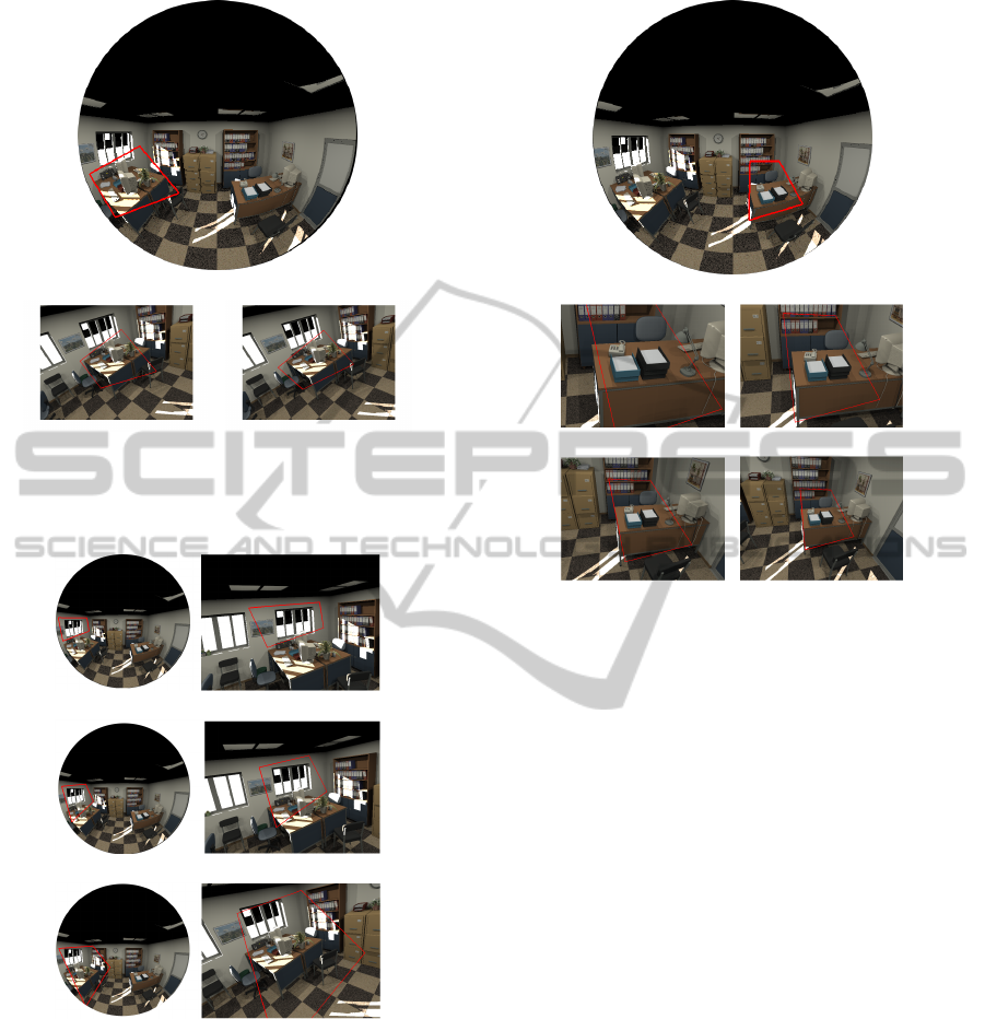
6.2.2 Experiments with Real Images
The master fisheye image (figure 9(a)) used for all
these experiments does not change while the images
from the PTZ camera are subject to many changes in
illumination or in the environment.
In the first experiment we selected a flat and well-
textured surface (see the red bounding box in fig.9(a))
which is matched among images from the perspective
camera. The resulting bounding box surrounding the
selected area can be shown in figure 9(b), we can see
that the matching is close to be perfect.
Figure 9(e) depicts a test with a planar area but
with a partial occlusion on the perspective image.
Even in this circumstance the recognition is still very
accurate. To assert our method we also applied it on
non-planar regions, those experiments are depicted in
figure 9(c)(d). Despite the planar patch assumption
ControlofaPTZCamerainaHybridVisionSystem
403

(a)
(b) (c)
(d) (e)
(f) (g)
(h)
Figure 9: Detection of various objects (a) Fisheye image
with selected ROIs, (b) (c) (d) (e) (f) (g) and (h) Detected
targets through PTZ images.
is not satisfied, the detection of the desired areas re-
mains precise.
Figure 9(f) is the result of a detection in very chal-
lenging conditions, in fact the selected area is not flat
and with occlusions. Even in these conditions our al-
gorithm achieves very good results.
While the other images assumes a optical zoom of
1X, figure 9(g) shows a result with a zoom of 5X. The
use of different zoom levels do not affect much the
performances of the proposed method. Finality the
last experiment (figure9(h)) proves the robustness of
our method to strong illuminations changes.
7 CONCLUSIONS
In this paper we have presented a flexible and efficient
approach to control a PTZ camera in a heterogeneous
vision system. We proved that it is possible to local-
ize a target with a PTZ camera using only information
from any omnidirectional camera respecting the SVP
assumption. Our method combines many advantages.
Indeed it performs well even in an unknown environ-
ment by scanning an epipolar circle. Furthermore the
detection of the target object is only based on geo-
metric assumptions, while most of the hybrid match-
ing methods in the literature use photometric descrip-
tors. Consequently, our approach can deal with strong
distortions, illumination changes and big scale differ-
ence without any rectification of the omnidirectional
image. It is also important to note that this template
matching can be used for any calibrated hybrid vision
system.
The provided set of qualitative and quantitative re-
sults show the great accuracy and flexibility offers by
our method which is capable to detect any kind of
ROI.
This work can be useful in many robotics or video
surveillance applications, for instance as an initializa-
tion for collaborative object tracking.
ACKNOWLEDGEMENTS
This work was supported by DGA (Direction Gen-
erale de l’Armement) and the regional council of Bur-
gundy.
REFERENCES
Adorni, G., Bolognini, L., Cagnoni, S., and Mordonini, M.
(2002). Stereo obstacle detection method for a hybrid
omni-directional/pin-hole vision system. In RoboCup
2001: Robot Soccer World Cup V, pages 244–250,
London, UK. Springer-Verlag.
Agapito, L., Hayman, E., and Reid, I. (2001). Self-
calibration of rotating and zooming cameras. Inter-
national Journal of Computer Vision, 45(2):107–127.
Amine Iraqui, H., Dupuis, Y., Boutteau, R., Ertaud, J.-Y.,
and Savatier, X. (2010). Fusion of omnidirectional
and ptz cameras for face detection and tracking. In
VISAPP2014-InternationalConferenceonComputerVisionTheoryandApplications
404

Emerging Security Technologies (EST), 2010 Interna-
tional Conference on, pages 18–23. IEEE.
Badri, J., Tilmant, C., Lavest, J., Pham, Q., and Sayd, P.
(2007). Camera-to-camera mapping for hybrid pan-
tilt-zoom sensors calibration. In SCIA, pages 132–
141.
Barreto, J. P. and Araujo, H. (2001). Issues on the geome-
try of central catadioptric image formation. In CVPR,
pages 422–427.
Bazin, J., Kim, S., Ghoi, D., J.Y.Lee, and Kweon, I. (2011).
Mixing collaborative and hybrid vision devices for
robotics applications. journal of Korea Robotics Soci-
ety.
Bouguet, J. Y. (2008). Camera calibration toolbox for Mat-
lab.
Chen, C.-H., Yao, Y., Page, D. L., Abidi, B. R., Koschan,
A., and Abidi, M. A. (2008). Heterogeneous fusion
of omnidirectional and ptz cameras for multiple ob-
ject tracking. IEEE Trans. Circuits Syst. Video Techn.,
18(8):1052–1063.
Courbon, J., Y.Mezouar, and Martinet, P. (2012). Evalu-
ation of the unified model of the sphere for fisheye
cameras in robotic applications. Advanced Robotics,
26(8-9):947–967.
Cui, Y., Samarasekera, S., Huang, Q., Greienhagen, M., and
Enhagen, M. G. (1998). Indoor monitoring via the
collaboration between a peripheral sensor and a foveal
senor. In In Proc. of the IEEE Workshop on Visual
Surveillance, pages 2–9. IEEE Computer Society.
Cyganek, B. and Gruszczy
´
nski, S. (2013). Hybrid computer
vision system for drivers’ eye recognition and fatigue
monitoring. Neurocomputing.
Ding, C., Song, B., Morye, A., Farrell, J. A., and Roy-
Chowdhury, A. K. (2012). Collaborative sensing in
a distributed ptz camera network. Image Processing,
IEEE Transactions on, 21(7):3282–3295.
Eynard, D., Vasseur, P., Demonceaux, C., and Fr
´
emont,
V. (2012). Real time uav altitude, attitude and mo-
tion estimation from hybrid stereovision. Autonomous
Robots, 33(1-2):157–172.
Fischler, M. A. and Bolles, R. C. (1981). Random sample
consensus: a paradigm for model fitting with appli-
cations to image analysis and automated cartography.
Commun. ACM, 24(6):381–395.
Fujiki, J., Torii, A., and Akaho, S. (2007). Epipolar ge-
ometry via rectification of spherical images. In Pro-
ceedings of the 3rd international conference on Com-
puter vision/computer graphics collaboration tech-
niques, MIRAGE’07, pages 461–471, Berlin, Heidel-
berg. Springer-Verlag.
Gould, S., Arfvidsson, J., Kaehler, A., Messner, M., Brad-
ski, G., Baumstarck, P., Chung, S., and Ng, A. Y.
(2007). Peripheral-foveal vision for real-time object
recognition and tracking in video. In In International
Joint Conference on Artificial Intelligence (IJCAI.
Liao, H. C. and Cho, Y. C. (2008). A new calibration
method and its application for the cooperation of
wide-angle and pan-tilt-zoom cameras. Information
Technology Journal, 7(8):1096–1105.
Marr, D. and Poggio, T. (1977). A theory of human stereo
vision. Technical report, Cambridge, MA, USA.
Mei, C., Benhimane, S., Malis, E., and Rives, P. (2008).
Efficient homography-based tracking and 3-d recon-
struction for single-viewpoint sensors. IEEE Transac-
tions on Robotics, 24(6):1352–1364.
Mei, C. and Rives, P. (2007). Single view point omni-
directional camera calibration from planar grids. In
IEEE International Conference on Robotics and Au-
tomation.
Micheloni, C., Rinner, B., and Foresti, G. L. (2010). Video
analysis in pan-tilt-zoom camera networks. Signal
Processing Magazine, IEEE, 27(5):78–90.
Neves, A. J., Martins, D. A., and Pinho, A. J. (2008).
A hybrid vision system for soccer robots using ra-
dial search lines. In Proc. of the 8th Conference on
Autonomous Robot Systems and Competitions, Por-
tuguese Robotics Open-ROBOTICA, pages 51–55.
Puwein, J., Ziegler, R., Ballan, L., and Pollefeys, M. (2012).
Ptz camera network calibration from moving people
in sports broadcasts. In Applications of Computer Vi-
sion (WACV), 2012 IEEE Workshop on, pages 25–32.
IEEE.
Raj, A., Khemmar, R., Eratud, J. Y., and Savatier, X.
(2013). Face detection and recognition under hetero-
geneous database based on fusion of catadioptric and
ptz vision sensors. In Proceedings of the 8th Interna-
tional Conference on Computer Recognition Systems
CORES 2013, pages 171–185. Springer.
Rameau, F., Habed, A., Demonceaux, C., Sidib
´
e, D., and
Fofi, D. (2012). Self-calibration of a ptz camera using
new lmi constraints. In ACCV.
Scotti, G., Marcenaro, L., Coelho, C., Selvaggi, F., and
Regazzoni, C. (2005). Dual camera intelligent sen-
sor for high definition 360 degrees surveillance. IEE
Proceedings-Vision, Image and Signal Processing,
152(2):250–257.
Ying, X. and Hu, Z. (2004). Can we consider central cata-
dioptric cameras and fisheye cameras within a unified
imaging model. In ECCV, pages 442–455.
ControlofaPTZCamerainaHybridVisionSystem
405
