
High Resolution Light Field Photography
from Split Ray Imaging and Coded Aperture
Shota Taki, Fumihiko Sakaue and Jun Sato
Nagoya Institute of Technology, Gokiso, Showa, Nagoya 466-8555, Japan
Keywords:
Computational Photography, Light Field Camera, Coded Aperture.
Abstract:
In this paper, we propose a method for obtaining high resolution 4D light fields by using low resolution camera
sensors and controllable coded apertures. Recently, 4D light filed acquisition has been studied extensively in
the field of computational photography. Since the 4D light filed consists of much lager information than the
ordinary 2D image, we have to use super high resolution camera sensors in order to obtain high resolution
4D light fields. In this paper, we propose a method for obtaining high resolution 4D light fields from low
resolution camera sensors. In this method, we combine the standard light field imaging technique with the
coded aperture. By using these techniques, we can obtain high resolution 4D light fields from low resolution
cameras with small number of image acquisitions. The efficiency of the proposed method is tested by real
images.
1 INTRODUCTION
Recently, new imaging techniques, namely computa-
tional photography, are widely studied. In the com-
putational photography, we use not only ordinary im-
age processing methods, but also special imaging de-
vices such as coded aperture(Veeraraghavan et al.,
2007), moving imaging sensor(Kuthirummal et al.,
2011) and so on. In particular, a light field cam-
era(Adelson and Wang, 1992; Georgiev et al., 2007;
Liang et al., 2008; Ng et al., 2005; Ng, 2006; Veer-
araghavan et al., 2008) is one of the most promis-
ing devices in the field of computational photography.
The light field camera can record 4-dimensional light
field including not only 2D position information but
also 2D directional information of light rays. The 4D
light filed includes much more information than the
ordinary 2D image, and thus, we can achieve much
more sophisticated image processing, which cannot
be accomplished by using ordinary camera devices.
For example, we can generate any images observedby
arbitrary focal plane, namely image refocusing, from
the 4D light filed(Veeraraghavan et al., 2007).
In order to obtain 4D light fields, many meth-
ods have been proposed(Adelson and Wang, 1992;
Georgiev et al., 2007; Liang et al., 2008; Ng et al.,
2005; Ng, 2006; Veeraraghavan et al., 2008), each
of which has different advantage and disadvantage.
For example, Ng et al.(Ng et al., 2005) proposed a
light field camera using a micro-lens array. In this
method, the micro-lens array is set in front of the
CCD/CMOS sensor, and then, light rays are separated
and projected into different pixels. Veeraraghavan et
al.(Veeraraghavan et al., 2007) used light modulation
masks, such as cosine mask, for separating light rays.
These methods enables us to separate and project dif-
ferent directional light rays into different pixels. We
call these methods as split ray imaging in this paper.
The split ray imaging is very useful because we
can obtain 4D light fields directly by a single shot
imaging. Therefore, we can obtain light fields accu-
rately, even if target objects are moving. However,
we need a large scale imaging sensor in this method,
since 4D light fields include much larger amount of
information than ordinary 2D images.
In contrast, Liang et al.(Liang et al., 2008) pro-
posed a light field camera, which enables us to obtain
4D light fields from an ordinary size imaging sensor.
In this camera, controllable coded aperture was used.
The aperture of this camera is divided into some num-
ber of pixels, and we can control the transmittance
of these pixels. For obtaining light fields efficiently,
the pattern of transmittance of the aperture is changed
shot by shot, and different sets of light fields are ob-
tained. Thus, we can obtain high resolution 4D light
fields from low resolution imaging sensors. Although
it can be achieved by using ordinary size sensors, we
have to take a lot of images changing the aperture
605
Taki S., Sakaue F. and Sato J..
High Resolution Light Field Photography from Split Ray Imaging and Coded Aperture.
DOI: 10.5220/0004739806050612
In Proceedings of the 9th International Conference on Computer Vision Theory and Applications (VISAPP-2014), pages 605-612
ISBN: 978-989-758-004-8
Copyright
c
2014 SCITEPRESS (Science and Technology Publications, Lda.)
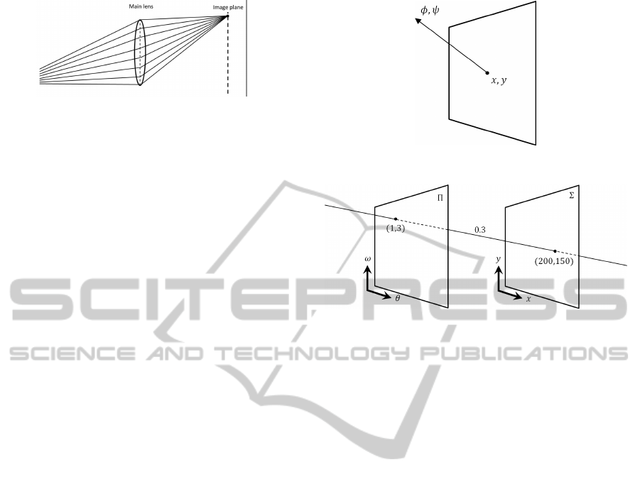
Figure 1: Light rays in an ordinary camera.
pattern for obtaining 4D light fields. Therefore, this
method can be applied just to static scenes.
In this paper, we combine the split ray imaging
and the coded aperture for obtaining high resolution
4D light filed from low resolution sensor and small
number of imaging. Moreover, the proposed light
field camera can control the trade off between the
resolution of image sensor and the number of imag-
ing. As a result, we can employ the best combination
of the resolution of image sensor and the number of
imaging.
2 4D LIGHT FIELD
We first explain 4-dimensional light field briefly.
Figure1 shows light rays in an ordinary camera, where
each pixel on the image plane receives all the light
rays, which go through the lens. Since all the rays are
mixed up at a single pixel, we cannot separate individ-
ual rays just from a single observation at the pixel. In
contrast, the light field camera enables us to observe
individual light rays, i.e. intensity of individual rays.
By using the information acquired by the light field
camera, we can achieve a variety of new applications,
such as image refocusing, changing viewpoint and so
on.
The light ray is represented by not only the posi-
tion but also the direction. Let us consider a light ray
observed at a pixel (x, y) on an image plane as shown
in Fig.2. Suppose the direction of the ray is indicated
by φ and ψ. Then, a single light ray can be considered
as a function of a point in the 4D space, which con-
sists of the position, x and y, and the direction, φ and
ψ. The 4D space is called a light field.
We often represent 4D light field by using a point
(x, y) on the image plane Σ and a point (θ, ω) on
the other plane Π as shown in Fig.3. In this case, θ
and ω corresponds to the direction of the ray. Thus,
L(x, y, θ, ω) represents a light ray in the light field.
For example, a light ray in Fig.3 is represented as
L(1, 3, 200, 150) = 0.3. Note, the plane Π is often de-
fined on a camera lens or on an aperture.
By using the light field, we can generate ordinary
2D images projected onto arbitrary image planes. The
intensities at each pixel in the image is computed by
Figure 2: 4D light field.
Figure 3: 4D light field represented by 2 different planes.
summing rays in all the direction. Thus, the ordinary
2D image I(x, y) can be computed from the light field
L(θ, ω, x, y) as follows:
I(x, y) =
ZZ
L(θ, ω, x, y)dθdω (1)
3 LIGHT FILED ACQUISITION
In recent years, many methods were proposed for ob-
taining 4D light fields. These methods can be classi-
fied into two groups. In this section, we explain these
two methods.
3.1 Split Ray Imaging
The most naive method for obtaining 4D light fields
is split ray imaging, in which each individual ray is
observed by each pixel in the image sensor. This is
achieved by using micro lens array, pin-hole array,
and so on. In this section, we consider split ray imag-
ing by using the pin-hole array model.
The pin-hole array consists of many pin-holes on
a grid. The pin-hole array is set in front of an im-
age sensor, such as CCD and CMOS. The light rays
pass through the main lens and the pin-holes succes-
sively. After that, they are received by image pixel on
the image plane as shown in Fig.4. In this case, res-
olution of ray position is determined by the number
of pin-holes. On the other hand, the resolution of ray
direction is determined by the number of pixels in the
image sensor. Figure 4 indicates a light filed camera
VISAPP2014-InternationalConferenceonComputerVisionTheoryandApplications
606
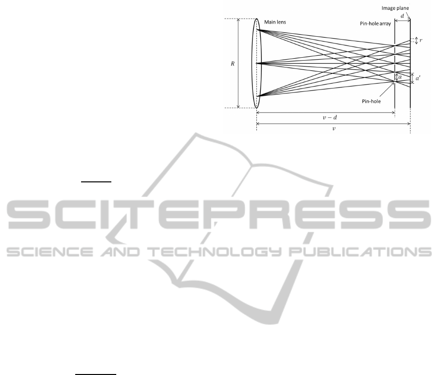
which can record 3× 3 directions and 5× 5 positions.
In this method, the pin-holes must be designed care-
fully, so that the image sensor behind the pin-holes
can capture individual rays properly. Thus, we next
consider the design of pin-holes.
At first, we consider the relationship among dis-
tance d between pin-hole and image plane, distance v
between main lens and pin-hole, size of pixel v, diam-
eter of main lens R and the resolution of light ray di-
rection N
l
. These parameters can be figured as Fig.4,
and their relationship can be described as follows:
R : N
l
r = (v− d) : d (2)
Therefore, the distance d can be described as follows:
d =
N
l
rv
N
l
r+ R
(3)
We next consider an appropriatedistance between two
adjacent pin-holes. If the distance is not set prop-
erly, light rays from different pin-holes are overlapped
each other on an image pixel, or we cannot use all
image pixels efficiently. Suppose a is an appropriate
distance between two adjacent pin-holes. Then, the
following relationship holds:
a : a
′
= (v− d) : v (4)
where, a
′
denotes the distance between the center
of projected rays through two adjacent pin-holes as
shown in Fig. 4. Note that a
′
is defined as a
′
= N
l
r.
Therefore, appropriate distance a can be described as
follows:
a =
N
l
r(v− d)
v
(5)
Finally, we can obtain proper pin-hole array
p(x, y) as follows:
p(x, y) =
∞
∑
k=−∞
∞
∑
l=−∞
δ(x− ka, y− la). (6)
By designing pin-holes according to (6), we can ob-
tain 4D light fields properly from 2D images.
In this method, however, we need a very high res-
olution image sensor in order to obtain 4D light fields
with sufficient resolution. This is because we repre-
sent 4-dimensional data by using 2-dimensional im-
age plane in this method. For example, if we want to
obtain 9 × 9 directional light rays at 400 × 400 posi-
tions, we need 3600 × 3600 image pixels. Therefore,
we need a large image sensor, which have large num-
ber of image pixels, in order to obtain light fields with
sufficient resolution.
Figure 4: Split ray imaging by a pin-hole array.
3.2 Coded Aperture
We next consider the coded aperture for obtaining 4D
light fields. Let us consider a controllable aperture
for light field acquisition. The aperture is constructed
from many pixels and we can control transmittance of
each pixel. A light field camera can be constructed by
using this controllable aperture and an ordinary image
sensor.
We first consider basic theory of light filed acqui-
sition by using coded aperture. As shown in Fig.3,
light rays in the 4D light field can be defined by two
planes. The image plane such as CCD and CMOS
sensors can be considered as one of these two planes,
and the controllable aperture can be considered as the
other plane. Let us consider the case where control-
lable aperture is set onto the main lens. In this case,
we can control light rays passing through the main
lens by controlling the transmittance of each pixel of
aperture. For example, we can obtain 4 × 3 × 300 ×
300 light field, if we use image sensor with 300×300
pixels and controllable aperture with 4× 3 pixels.
Suppose a pixel (i, j) on the aperture is open, and
the other pixels on the aperture are closed. Let I
ij
(x, y)
be an observed intensity at pixel (x, y) in the image
sensor, when the pixel (i, j) is open. Then, the ob-
served intensity I
ij
(x, y) can be described by the 4D
light filed L(θ, ω, x, y) as follows:
I
ij
(x, y) =
L(θ, ω, x, y) , (θ, ω) = (i, j)
0 , (θ, ω) 6= (i, j)
(7)
Therefore, we can obtain the light field as a set of
images under different aperture patterns as follows:
L(i, j, x, y) = I
ij
(x, y) (i, j = 1, ··· , n), (8)
where n indicates the number of pixels in the control-
lable aperture.
However, obtained image intensities become very
small, since most of the pixels in the aperture are
closed. As a result, the S/N ratio of obtained light
HighResolutionLightFieldPhotographyfromSplitRayImagingandCodedAperture
607

field becomes very bad. However, we can avoid the
problem by using the coded aperture.
Let us consider a case, where we have k different
coded apertures w
i
(i = 1, . . . , k). Note, w
i
∈ [0, 1]
n
.
Then, w
i
represents the transmittance of each pixel in
the controllable aperture. When we use i-th coded
aperture w
i
, the light field L(θ, ω, x, y) is projected
into image I
i
(x, y) as follows:
I
i
(x, y) =
∑
θ,ω
w
i
(θ, ω)L(θ, ω, x, y), (9)
where w
i
(θ, ω) denotes a component of w
i
, which cor-
responds to direction θ and ω.
Let W be a set of coded apertures as follows;
W =
w
1
w
2
.
.
.
w
k
=
w
11
w
12
··· w
1n
w
21
w
22
w
2n
.
.
.
.
.
.
.
.
.
w
k1
w
k2
··· w
kn
(10)
If we make
w
i
large, the S/N ratio becomes bet-
ter. Liang et al.(Liang et al., 2008) determined W by
minimizing the following cost function E(W):
E(W) = Trace((W
⊤
W)
−1
) (11)
We next consider reconstruction of 4D light fields
from observed images under coded apertures. Equa-
tion (9) shows that the observed images are summa-
tion of light rays with transmittance of coded aperture.
That is, we can describe the relationship between ob-
served images and the intensities of light rays by us-
ing the transmittance matrix W as follows:
I
1
(x)
I
2
(x)
.
.
.
I
k
(x)
=
w
11
w
12
··· w
1n
w
21
w
22
w
2n
.
.
.
.
.
.
.
.
.
w
k1
w
k2
··· w
kn
L(1, x)
L(2, x)
.
.
.
L(n, x)
,
(12)
where I
k
(x) denotes an intensity at position x under
k-th coded aperture and L(θ, x) denotes a light ray at
position x with direction θ. We rewrite (12) as fol-
lows:
I = WL (13)
where I = [I
1
(x), I
2
(x), . . . , I
k
(x)]
⊤
and L = [L(1, x),
L(2, x), . . . , L(θ, x)]
⊤
. Thus, we can estimate light
rays as follows:
ˆ
L = arg min
L
WL− I
2
, L ≥ 0 (14)
where
·
2
indicates L2-norm of vectors. We can
obtain complete light field by this estimation.
In this method, we can obtain high resolution light
field by using ordinary image sensor. However, we
need a lot of images under different coded apertures.
This means we need long time to obtain a sufficient
light field.
Figure 5: Light field acquisition by using coded apertures.
4 LIGHT FIELD FROM SPLIT
RAY IMAGING WITH CODED
APERTURE
As described in section 3, there exists two types
of method for obtaining light fields. In the former
method, super high resolution image sensors are re-
quired for obtaining light fields with sufficient reso-
lution, although they are obtained by a single shot.
In the second method, we have to iterate image ac-
quisition several times, although light fields can be
obtained by using standard resolution cameras. In
this section, we propose a new method for obtaining
light field efficiently by combining these two existing
methods. In our method, we use the pin-hole array
(or micro lens array) and the coded aperture simul-
taneously. As a result, we can reduce the resolution
of image sensor and the number of image acquisition
required for obtaining light fields with sufficient res-
olution. We can also control the trade off between the
resolution of image sensor and the number of image
acquisition according with the situation. This prop-
erty is practically very important, since we have to
obtain sufficient light fields under limited conditions
in general.
We first consider the acquisition of 2D light field
by using 1D camera in order to simplify the prob-
lem. Let us consider the case, where 9 light rays
L( j, i) ( j = 1, · ·· , 9) go through the coded aperture
and pin-holes, and are projected onto 3 pixels in the
image sensor as L
′
(m, i) (m = 1, ·· · , 3), as shown in
Fig.6. Because of the geometric relationship shown
in Fig.6, L(1, i), L(2, i) and L(3, i) are projected onto
L
′
(3, i). Similarly, L(4, i), L(5, i) and L(6, i) are pro-
jected onto L
′
(2, i), and L(7, i), L(8, i) and L(9, i) are
projected onto L
′
(1, i). We can control the transmit-
tance of aperture in front of the main lens. Let w
kj
be the transmittance of j-th pixel of k-th aperture
pattern w
k
. Then, the relationship between the light
field L( j, i) ( j = 1, · ·· , 9) and the observed intensity
L
′
k
(m, i) (m = 1, ··· , 3) under k-th aperture pattern can
be described as follows:
VISAPP2014-InternationalConferenceonComputerVisionTheoryandApplications
608
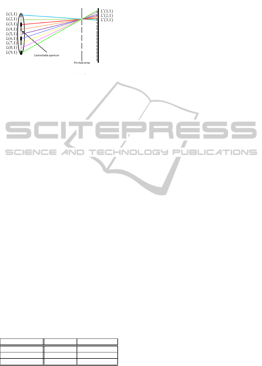
Figure 6: Light field acquisition from split ray imaging and
coded aperture.
L
′
k
(1, i) =
9
∑
j=7
w
kj
L( j, i) (15)
L
′
k
(2, i) =
6
∑
j=4
w
kj
L( j, i) (16)
L
′
k
(3, i) =
3
∑
j=1
w
kj
L( j, i) (17)
Since 3 constraints are obtained for light field L( j, i)
from each aperture pattern, we can estimate light field
L( j, i) from images taken under 3 different aperture
patterns. Note, we need 9 different aperture patterns,
if we do not combine the pin-hole array. Furthermore,
we need 9 image pixels if we do not combine the
coded aperture. Thus, the proposed method can de-
crease the number of image acquisition and the size
of image sensor. As a result, the proposed method
can solve the problem of coded aperture method and
the problem of split ray imaging method.
By using the proposed method, we can obtain high
resolution light fields by using a normal image sensor
with reasonable number of image acquisition. For ex-
ample, if we want to obtain a light field with 9 × 9
directions and 640 × 480 positions by using the stan-
dard lens array method, we need an image sensor with
5760 × 4320 pixels. Also, if we want to obtain the
same light field by using the coded aperture method,
we need 81 image acquisitions. However, if we use
the proposed method, the same light field can be ob-
tained by using an image sensor with 1920 × 1440
pixels and 9 image acquisitions as shown in Tab.1.
Thus, the proposed method enables us to obtain high
resolution light fields from reasonable sensors and
reasonable image acquisition.
Table 1: Relationship between the size of image sensor and
the number of image acquisitions.
# of pixels # of acquisitions
Split ray imaging 5760× 4320 1
Coded aperture 640× 480 81
Proposed method 1920× 1440 9
5 POINT SPREAD FUNCTION OF
LIGHT RAYS
5.1 Light Field Representation by PSF
We can obtain high resolution light fields by using the
proposed method described in section 4. However,
the obtained light fields may not be accurate because
of the spread of light in imaging. This problem often
occurs when we use micro lens arrays for separating
rays. The light rays passed through a micro lens often
spread over some pixels in the image sensor. The blur
occurs when a distance between the micro-lens and
the image plane does not agree with the focal length
of the micro lens. The blur of the light rays can be
described by a point spread function (PSF).
The PSF can be represented by an image taken un-
der a point light source. Thus, the PSF can be ob-
tained by opening a single pixel on the controllable
aperture and taking images.
Let p
j
be a point spread function of j-th pixel in
the coded aperture. The observed image I under a
light field L( j, i) can be described as follows:
I =
n
∑
j=1
p
j
L( j, i). (18)
This equation can be rewritten as follows:
I =
p
1
··· p
n
L(1, i)
.
.
.
L(n, i)
. (19)
Note that the number of component of I and p
j
is
smaller than n, since the resolution of observed image
is lower than the resolution of light field. Relationship
between unblurred light field [L(1, i), ..., L(n, i)]
⊤
and
acquired images under differentcoded aperture can be
described as follows:
I
1
.
.
.
I
k
=
w
11
p
1
··· w
1n
p
n
.
.
.
w
k1
p
1
··· w
kn
p
n
L(1, i)
.
.
.
L(n, i)
,
(20)
where I
k
denotes k-th acquired image and w
kj
denotes
the transmittance of j-th pixel in k-th aperture pattern,
i.e. k-th image acquisition. Then, we can obtain un-
blurred light field [L(1, i), ..., L(n, i)]
⊤
under different
coded apertures as follows:
L(1, i)
.
.
.
L(n, i)
=
w
11
p
1
··· w
1n
p
n
.
.
.
w
k1
p
1
··· w
kn
p
n
+
I
1
.
.
.
I
k
,
(21)
HighResolutionLightFieldPhotographyfromSplitRayImagingandCodedAperture
609

where A
+
indicates the pseudo inverse of A, and is
computed by A
+
= (A
⊤
A)
−1
A
⊤
. Therefore, we have
to estimate the PSF in order to obtain unblurred light
fields from blurred light fields.
5.2 Estimation of PSF
Eq. (19) describes a linear relationship between PSF
and light rays. Since it is linear, we can estimate PSF
linearly from a set of images taken under known light
fields. For this objective, we use a white Lambertian
surface as a source of the standard light field. This is
because the reflected lights of a white Lambertian sur-
face have constant unit intensity at any points on the
surface and toward any directions from the surface.
If we observe a white Lambertian surface by using
the proposed light field camera, the relationship be-
tween observed image I and PSF p
j
can be described
as follows:
I =
n
∑
j=1
w
j
p
j
(22)
where, w
j
denotes the transmittance of j-th pixel of
the aperture. The equation indicates that we can ob-
tain a PSF directory by opening each pixel of the aper-
ture and observing the image. However, the S/N ra-
tio of obtained PSF is bad, because we cannot ob-
tain enough image intensity if most of the aperture
is closed. In order to avoid the problem, we use the
least means square method.
By obtaining k images of Lambertian surface un-
der different coded apertures, we have a system of lin-
ear equations as follows:
I
1
··· I
k
=
p
1
··· p
n
w
⊤
1
··· w
⊤
k
(23)
Thus, a set of PSF p
1
, ··· , p
n
can be estimated as fol-
lows:
p
1
··· p
n
⊤
=
w
⊤
1
··· w
⊤
k
⊤+
I
1
··· I
k
⊤
. (24)
Then, from (21) we can estimate unblurred light
field, even ifthe observed images are blurred. We next
consider experimental results by using our proposed
method in the following sections.
6 EXPERIMENTAL RESULTS
6.1 Environment
In this section, we show some experimental results
from the proposed method. At first, we explain the
(a) (b)
Figure 7: Experimental environment (a) and coded aperture
by controllable aperture(b).
experimental devices and environments. In this exper-
iment, a camera and a main lens were set separately
as shown in Fig.7(a) in order to adjust camera param-
eters accurately. The camera used in this experiment
is TOSHIBA Teli CSC6M85BMP11, and 1210× 730
images are taken by this camera. A micro-lens array is
set in front of the CMOS sensor in camera device. The
micro-lens array consists of 242 × 146 micro-lenses
and the focal length of each lens is 0.54mm. The fo-
cal length of main lens is 72.7mm, and the distance
between lenses is 250mm. The target objects are put
in front of the main lens. The distance between the
stage and the main lens is 110 ∼ 130mm. A control-
lable aperture is set in front of the camera as shown
in Fig. 7(a). It is an LCD with 15× 15 pixels. Fig-
ure 7(b) shows an example of coded aperture gener-
ated by the controllable aperture. Note that we cannot
perfectly obstruct a light, even if the aperture is com-
pletely closed. Therefore, we subtracted an ambient
image obtained by closing all the aperture from input
images in order to eliminate ambient intensity.
Figure 8 shows an image taken when all the pix-
els of aperture are opened. In this figure, some re-
gions around the center of image is magnified. The
small circles in the image represent different direc-
tional light rays to the same destination (micro-lens).
The number of the circles correspond to the number
of micro-lens and it is 242× 146. The size of circle is
5×5, and thus, the maximum resolution of directional
component is 5 × 5 in this image. The circles are
not aligned in grid because of the distortion of micro-
lens array, etc. Thus, we aligned the circles in grid
by using thin plate spline transformation. The resolu-
tion of light field in this image is 242× 146× 5× 5.
In this experiment, we reconstruct a light field with
242× 146× 15× 15 by using the proposed method.
6.2 PSF Estimation
We first estimate PSF by the method described in sec-
tion 5.2. The resolution of controllable aperture is
15 × 15, and then, we needed 225 or more than 225
VISAPP2014-InternationalConferenceonComputerVisionTheoryandApplications
610
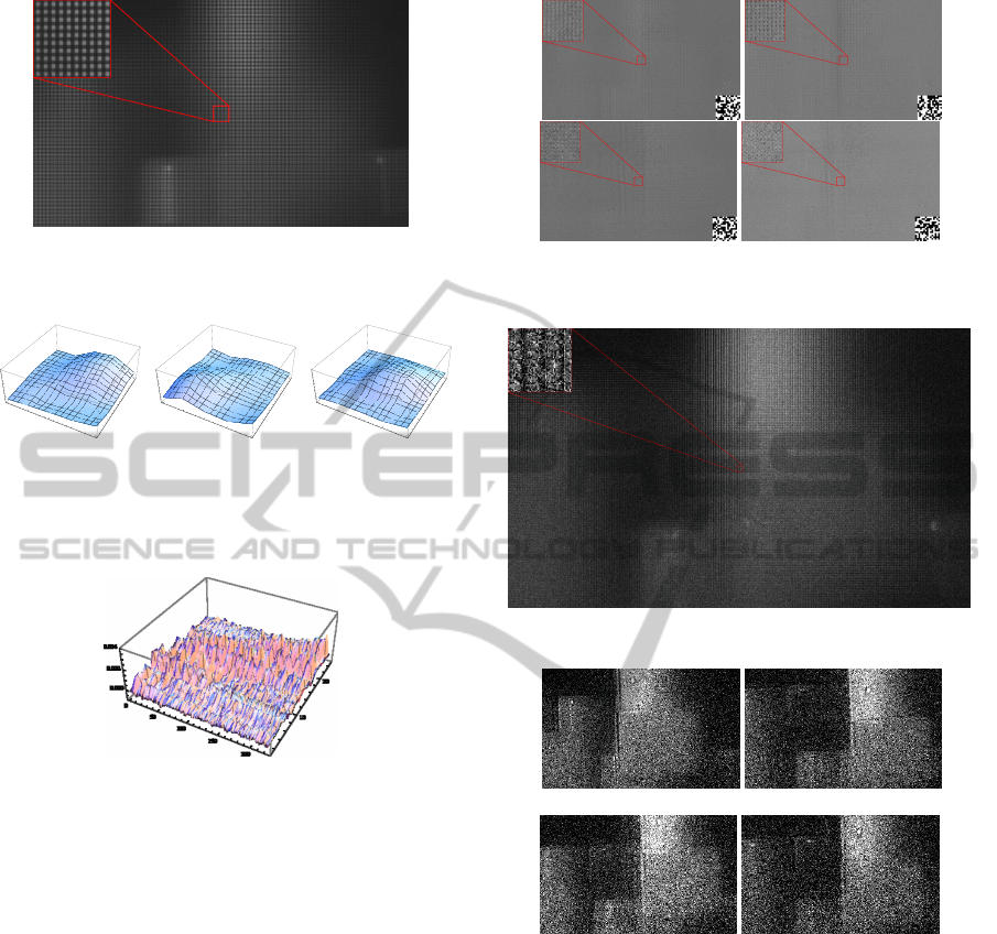
Figure 8: Image taken by opening all the pixels in control-
lable aperture.
1
2
3
4
5
1
2
3
4
5
0.000
0.002
0.004
(a) C(10, 15)
1
2
3
4
5
1
2
3
4
5
0.000
0.002
0.004
(b) C(2, 3)
1
2
3
4
5
1
2
3
4
5
0.000
0.002
0.004
(c) C(8, 8)
Figure 9: Examples of estimated PSF. (a), (b) and (c) show
PSF when aperture (10,15), (2,3) and (8,8) is opened, re-
spectively.
Figure 10: Estimated set of PSF.
images to estimate set of PSF. In order to estimate a
set of PSF accurately, we used 675 images for this
estimation. We used a Lambertian plane as a calibra-
tion object. The estimated PSF of a destination are
shown in Fig.9. In these figures, intensities of PSF
is represented by color, and each figure shows PSF
when aperture (10,15), (2,3) and (8,8) is opened, re-
spectively. Figure 10 shows estimated set of PSF de-
scribed in Eq.(23). In these results, intensity of light
ray was not convergedto a pixel nevertheless only one
pixel of aperture was opened. The fact indicates that
light field recorded by the camera is blurred and we
need PSF for accurate light field recording.
6.3 Reconstruction of Light Field
We next show reconstructed high resolution light field
by the proposed method. In this experiment, we re-
constructed 15 × 15 directional light rays from 5 × 5
directional light rays at each position, and thus, 9 or
more than 9 images are required for reconstruction.
Figure 11: Examples of input images and coded apertures.
Coded aperture is shown in right bottom in each image.
Figure 12: Reconstructed high resolution light field.
(15,9) (2,5)
(4,11) (5,7)
Figure 13: Sub-images of light field which have the same
directional light rays.
In this experiment, we used 75 images taken under
different coded apertures for accurate light field re-
construction. Figure11 shows some examples of input
images.
From these images, high resolution light field
was reconstructed and the result is shown in Fig.12.
Figure13 shows sub-images of light field. In these fig-
ures, images were generated from a set of light rays
with the same direction.
For comparison, the same light field was recon-
structed without considering PSF. The results are
shown in Fig.14. In this figure, the reconstructed light
field is blurred and is not accurate. It indicates the
HighResolutionLightFieldPhotographyfromSplitRayImagingandCodedAperture
611
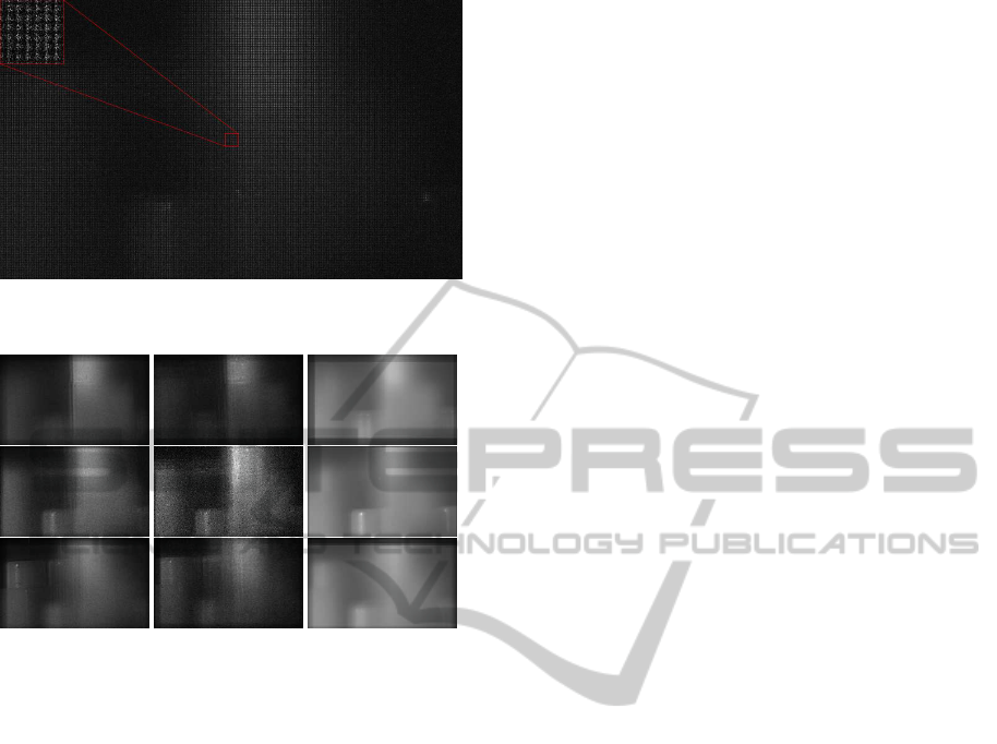
Figure 14: Reconstructed high resolution light field without
considering PSF.
(a) proposed method
(b) proposed method
without PSF
(c) input image
Figure 15: Refocused images from a light field obtained by
(a) proposed method, (b) proposed method without consid-
ering PSF and (c) direct input image. Images in top, middle
and bottom rows are focused to the nearest object (left ob-
ject), middle object (center object) and the farthest object
(left object) respectively.
effectiveness of considering PSF in light field recon-
struction.
6.4 Image Refocusing by using Light
Field
We finally show the results of image refocusing from
reconstructed light field. For comparison, we refo-
cused images from (a) result of the proposed method,
(b) result without considering PSF and (c) low resolu-
tion input image. Figure 15 shows refocused images.
In these results, refocused image in (b) is blurred
since the reconstructed light field is also blurred. Re-
sult in (c) is also blurred since input light field does
not have sufficient resolution. In contrast, result from
the proposed method in (a) is accurate. This is be-
cause we can use accurate and high resolution light
field for refocusing. The result indicates that the ad-
vantage of the proposed method.
7 CONCLUSIONS
In this paper, we proposed a method for obtaining
high resolution 4D light fields from standard camera
with reasonable number of image acquisitions. In par-
ticular, we showed that by combining the split ray
imaging, such as micro lens array, with the coded
aperture, we can reduce the number of image pixels
as well as the number of image acquisitions required
for obtaining high resolution light fields. Further-
more, we presented a method for calibrating PSF of
the proposed light field acquisition method by using
the coded aperture.
The proposed method is very practical, since we
can control the trade off between the number of image
pixels and the number of image acquisitions accord-
ing to the purpose. Thus, our method can be applied
to many applications.
REFERENCES
Adelson, T. and Wang, J. (1992). Single lens stereo with
a plenoptic camera. IEEE Transactions on Pattern
Analysis and Machine Intelligence, 14(2):99–106.
Georgiev, T., Intwala, C., and Babacan, D. (2007). Light-
field capture by multiplexing in the frequency domain.
Technical report.
Kuthirummal, S., Nagahara, H., Zhou, C., and Nayar, S. K.
(2011). Flexible depth of field photography. IEEE
Transactions on Pattern Recognition and Machine In-
telligence, 33(1):58 – 71.
Liang, C., Lin, T., Wong, B., Liu, C., and Chen, H.
(2008). Programmable aperture photography: Mul-
tiplexed light field acquisition. In Proc. ACM SIG-
GRAPH2008.
Ng, R. (2006). Digital light field photography. PhD thesis,
Stanford, CA, USA. AAI3219345.
Ng, R., Levoy, M., Br´edif, M., Duval, G., Horowitz, M., and
Hanrahan, P. (2005). Light field photography with a
Hand-Held plenoptic camera. Technical report.
Veeraraghavan, A., Agrawal, A., Raskar, R., Mohan, A.,
and Tumblin, J. (2008). Non-refractive modulators for
encoding and capturing scene appearance and depth.
In Proc. IEEE Conference on Computer Vision and
Pattern Recognition.
Veeraraghavan, A., Raskar, R., Agrawal, A., Mohan, A.,
and Tumblin, J. (2007). Dappled photography: Mask
enhanced cameras for heterodyned light fields and
coded aperture refocusing. ACM Trans. Graph, 26.
VISAPP2014-InternationalConferenceonComputerVisionTheoryandApplications
612
