
3D Object Emphasis using Multiple Projectors
Shohei Takada, Fumihiko Sakaue and Jun Sato
Nagoya Institute of Technology, Gokiso, Showa, Nagoya 466-8555, Japan
Keywords:
3D Object Emphasis, Projector Camera Systems, Multiple Projectors.
Abstract:
In this paper, we propose a method for emphasizing 3D shapes by using patterned light projection from mul-
tiple projectors. In this method, we project patterned lights from multiple projectors. Then, the patterned
lights are mixed up at the surface of objects. As a result, object regions which are different from preregistered
3D shapes are colored and emphasized visually. In this method, we do not need any computation for image
processing, since the image processing is achieved by mixing lights projected from multiple projectors. Fur-
thermore, we do not need to find image correspondences in order to obtain 3D information of objects. In this
paper, we propose a method for generating projection patterns for visualizing small difference in 3D shapes
such as defects of shape. The efficiency of the proposed method is test by using multiple projectors.
1 INTRODUCTION
3D reconstruction from multiple camera images is
one of the most important problem in the field of com-
puter vision, and it has been studied extensively for
many years. The existing reconstruction methods can
be classified into 2 major methods.
The first one is called passive method (Hartley
and Zisserman, 2000; Tomasi and Kanad, 1992; Seitz
et al., 2006). In the passive method, multiple cameras
are used, and the correspondence of image features,
such as points and lines, are extracted and matched
in multiple images. Then, the 3D shape of object is
reconstructed from the correspondences by triangula-
tion. Although the method can be applied to various
scenes, we need some texture on the surface of object
for obtaining correspondences.
The second one is called active method (Gokturk
et al., 2004). In this method, feature points are pro-
jected onto objects from light projection devices, such
as projectors. Then, 3D shape of objects is recon-
structed from the projected feature points by triangu-
lation. This method sometimes has an advantage over
passive method, since it can be applied even if the ob-
jects do not have any texture on the surface.
Although these two methods provide us good 3D
measurements and are used in various applications in
recent years, both of them suffer from an unavoidable
fatal problem. That is wrong correspondence prob-
lem. Since these methods are based on correspon-
dences between cameras and projectors, if the cor-
respondences are wrong, it is impossible to recover
accurate 3D information from these methods. Al-
though many methods have been proposed for reduc-
ing wrong correspondences, it is impossible eliminate
the wrong correspondence problem completely.
In order to avoid this fatal problem, the coded
projection (Sakaue and Sato, 2011) was proposed re-
cently. In this method, 3D shape information is trans-
formed into color information by using the triangula-
tion of multiple projector lights. Since the triangula-
tion is achieved by mixing the multiple lights on ob-
jects, the correspondence problem never happens.
Furthermore, Nakamura et. al (Nakamura et al.,
2010) proposed a method for emphasizing 3D shape
of object by using multiple projectors. They showed
that it is possible to visualize the difference in shape
just by projecting multiple coded lights on to objects.
Although they showed a possibility of visualizing the
defects of shape just by projecting coded lights, they
also clarified that it is difficult to paint and emphasize
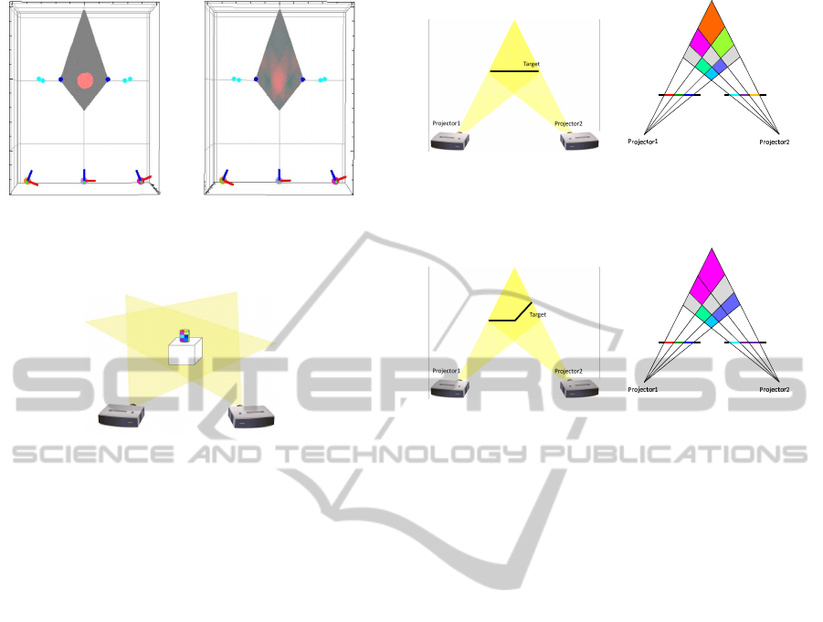
3D space freely. For example, Fig. 1 shows the results
from their method. Although we wanted to emphasize
3D space as Fig.1 (a), the result from their method is
as shown in Fig.1 (b), and we cannot emphasize the
detail of 3D shapes.
In this paper, we propose a method for empha-
sizing 3D shape accurately just by projecting coded
lights from multiple projectors. In particular, we pro-
pose a method for visualizing small change in shape
as shown in Fig.2. In this method, we focus on not
object region but object surface. Since there exists
187
Takada S., Sakaue F. and Sato J..
3D Object Emphasis using Multiple Projectors.
DOI: 10.5220/0004740201870193
In Proceedings of the 9th International Conference on Computer Vision Theory and Applications (VISAPP-2014), pages 187-193
ISBN: 978-989-758-003-1
Copyright
c
2014 SCITEPRESS (Science and Technology Publications, Lda.)
(a) Objective color (b) Projected result
Figure 1: 3D emphasis from (Nakamura et al., 2010): Ob-
jective color (a) and projected result (b).
Figure 2: Emphasis of small difference in 3D shape.
one-to-one correspondencebetween a point on the ob-
ject surface and a point in the projection image, we
can emphasize the detail of 3D shape. The proposed
method can be applied to various kinds of applica-
tions, such as defect visualization in factory.
2 3D SHAPE EMPHASIS BY
COLOR INFORMATION
2.1 3D Shape Emphasis by Multiple
Projection
We first explain the basic idea of our 3D shape empha-
sis. Suppose we have multiple projectors, and these
projectors project lights onto the surface of objects in
the scene. For simplify the problem, we assume these
object surfaces are Lambertian in this paper.
The images projected from these projectors are
mixed on the object surface. Therefore, we observe
mixed color of projected patterns on the surface. Let
I
1
= [I
1
1
, ··· , I
1
N
] be a projected pattern from projector
1 and let I
2
= [I
2
1
, ··· , I
2
N
] be a projected pattern from
projector 2, where i-th components in the projected
patterns, I
1
i
and I
2
i
, are projected to i-th point on the
surface. Under the condition, observed color I
i
at i-th
surface point can be described as follows:
I
i
= I
1
i
+ I
2
i
. (1)
Now, if I
1
i
and I
2
i
are complementary colors to
(a) Target object (b) Projected result
Figure 3: 3D shape emphasis by multiple projection onto
planar surface.
(a) Target object (b) Projected result
Figure 4: 3D shape emphasis for non-planar surface.
each other, we observe white color on the object sur-
face. In this paper, we call a surface, which is col-
ored to white by the combination of projected lights,
as basis surface, and its shape is called basis shape.
By controlling the projection patterns, we can control
the basis shape arbitrarily.
Note that each pixel of these projectors must be
corresponding to each other on the basis surface. In
order to estimate the correspondences, we use a cam-
era. However, once the correspondences are obtained
we do not need any camera afterwards.
In order to simplify the explanation, we consider
the case where basis surface is planar as shown in
Fig.3 (a). If we project patterned lights from two pro-
jectors as shown in Fig.3 (b), then the 3D point on
the basis surface is colored to white. For example,
the most right pixel of each projector is red and cyan,
and these colors are mixed on the basis surface, and
thus the basis surface is colored to white. If the object
surface is not at the basis surface position, i.e. object
shape is changed, combination of projected colors is
changed, and mixed colors at the object surface are
changed to other colors as shown in Fig.3 (b). The
method can also be applied to non-planar surface as
shown in Fig.4. Note, the number of pixels of pro-
jectors is limited to 3 for simplicity of explanation in
Fig. 3 and Fig. 4. Since the actual projectors have
large number of pixels, we can design smooth curved
surfaces as basis shape.
Unfortunately, the intensity of surface illuminated
by projector lights is not determined just by the in-
tensity of projector lights, and it also changes accord-
VISAPP2014-InternationalConferenceonComputerVisionTheoryandApplications
188

ing to the reflectance and orientation of the surface.
Thus, we next consider a more realistic light projec-
tion model.
Let R =diag(ρ
r
, ρ
g
, ρ
b
) be a diagonal matrix,
whose diagonal components are the reflectance at a
surface point X
ij
, where ρ
r
, ρ
g
and ρ
b
indicate re-
flectance of each color. Suppose θ
1
and θ
2
are the
angles between the surface normal and the light ori-
entation of projector 1 and 2 respectively. Then, the
observed color I
i
can be described as follows:
I
i
= R(
1
L
2
1
I
1
i
cosθ
1
+
1
L
2
2
I
2
i
cosθ
2
), (2)
where L
1
and L
2
denote distance from each projector
to X
ij
. Therefore, the complementary color I
2
i
with
respect to I
1
i
can be determined as follows:
I
2
i
=
L
2
2
cosθ
2
R
−1
W−
1
L
2
1
I
1
i
cosθ
1
, (3)
where, W denotes a white color.
In order to determine a pair of complementary
colors as shown in Eq.(3), we need not only pixel
correspondences but also normal orientation of ob-
ject surfaces. Estimation of these parameters can be
estimated by ordinary 3D shape measurement meth-
ods(Gokturk et al., 2004). Although we need cameras
for this estimation, cameras are not necessary after the
calibration. Estimation of these parameters is not the
main problem of this paper, and thus, we assume that
these parameters are known in this paper.
2.2 Epipolar Geometry between
Projectors
We next consider the epipolar geometry between
projectors. As we have seen, the observed color
changes according to the change in corresponding
pixels in our method. Seemingly, we have to con-
sider 2-dimensional changes of correspondence, since
the image plane is 2D. However, we have only 1-
dimensional variation in correspondence, since the
epipolar-constraint exists in image planes of two pro-
jectors similar to cameras.
The epipolar constraint for 2 projector images can
be described by a fundamental matrix F as follows:
m
′⊤
Fm = 0, (4)
where m and m
′
are a pair of corresponding points
in two images. Let us consider the epipolar line l
′
=
Fm, which corresponds to m. Then, the relationship
between l
′
and m
′
can be described as follows:
m
′⊤
l
′
= 0. (5)
This equation indicates that a corresponding point of
m exists on the epipolar line l
′
regardless of 3D shape.
Thus, the correspondence of color changes only on
the epipolar line, and we can consider change of col-
ors in each epipolar line. In the following sections,
we assume that the fundamental matrix of two pro-
jectors is given. Then, we consider desirable patterns
on epipolar lines for 3D shape emphasis.
3 PROJECTION PATTERNS FOR
3D OBJECT EMPHASIS
3.1 Random Pattern
We next consider projection patterns for projectors.
As shown in Eq.(3), if one of two projection patters
is determined, the other projection pattern can be de-
termined automatically as complementary color pat-
terns.
The projection pattern should satisfy the following
conditions for efficient 3D emphasis.
1. There exist no identical colors on the epipolar
line.
2. The colors of adjacent pixels must be different
largely.
If the first condition is satisfied, there exists no white
region except basis shape, since a complementary
color does not exist on the epipolar line of the other
projector except the basis shape. If the second con-
dition is satisfied, the change in color caused by the
change in shape becomes large.
There are many sets of colors which satisfies the
above two conditions, and one efficient method for
finding them is to select a set of colors randomly from
the RGB color space. The selected colors are dis-
tributed uniformly in RGB space, and both of two
conditions are satisfied in most of the case. If the
selected set of colors does not satisfy the conditions,
just iterate the random selection until the selected set
of colors satisfies the conditions.
3.2 Color Pattern Selection in
Frequency Space
We next consider color pattern selection more system-
atically. For this objective, we consider the color pat-
tern in Frequency space, and modify the conditions
described in section 3.1 as follows:
1. The wavelength of color pattern is longer than im-
age size.
3DObjectEmphasisusingMultipleProjectors
189
(a) Projection pattern from high frequency components.
(b) Projection pattern from low frequency components.
Figure 5: Example of projection patterns for 3D shape em-
phasis. Upper pattern consists of R{2,13}, G{3,11} and
B{5,7}. Lower pattern consists of R{11,29}, G{13,23} and
B{17,19}.
2. The frequency of color pattern must be as high as
possible.
If the first condition is satisfied, there exist no same
color on the epipolar line. In addition, since the fre-
quency of color pattern is high as described in the
second condition, colors on the epipolar line changes
drastically.
Although the first condition and the second condi-
tion seem to be conflict to each other, it is possible to
satisfy these two conditions simultaneously. This is
because the color consists of 3 bands, i.e. R, G and B,
and the minimum common multiple of 3 wavelengths
of R, G and B is the wavelength of whole color pat-
tern. For example, if the wavelength of red, green
and blue components are l, m and n and if they are
prime numbers, the wavelength of whole pattern is
l × m × n. Furthermore, wavelength of whole pat-
tern become longer when each color component has
several frequencies. Therefore, we can easily obtain
sufficiently long wavelengthincluding high frequency
components. Figure 5 shows examples of color pat-
tern. In upper pattern, the wavelengths of R, G and B
patterns are {2,13}, {3,11} and {5, 7}. In this pattern,
the color of each pixel changes drastically, while there
are no same color in the pattern. In lower pattern,
the wavelengths of R, G and B patterns are {11,29},
{13,23} and {17, 19}. In this pattern, change in color
is smoother than that of upper pattern, since the fre-
quency of each component is lower than that of upper
ones.
We can control the sensitivity of change in colors
easily by considering patterns in frequency space. If
we would like to detect small change in shape vividly,
we should use high frequency components for gener-
ating projection patterns. In contrast, we can ignore
small changes in shape and detect only large scale
change in shape, if we use low frequencycomponents.
As a result, we can use efficient patterns according to
the purpose. In the following sections, we show some
examples of our 3D shape emphasis.
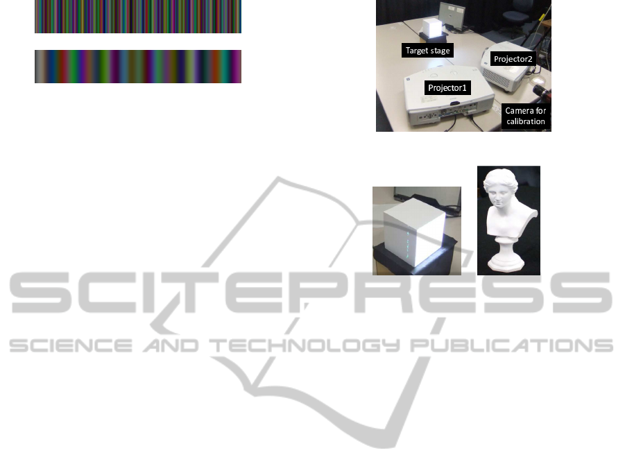
Figure 6: Experimental environment.
(a) Cube (b) Sculpture
Figure 7: Target objects for 3D shape emphasis.
4 EXPERIMENTAL RESULTS
4.1 Environment
In this section, we show some results in 3D shape
emphasis. We first explain our experimental environ-
ment. In these experiments, two projectors were used
and they were set as shown in Fig.6. The projectors
are EPSON EB-G5750WU. The image size projected
from these projectors is 800×600. The camera in this
image was used just for extracting correspondences
in images of two projectors. The camera was not used
for 3D shape emphasis at all. As target objects, a cube
shown in Fig.7 (a) and a sculpture in (b) were used.
The targets are made of gypsum and their surface can
be considered as Lambertian surface. The targets are
set on a target stage in Fig.6 and they were moved 1.5
cm and 3 cm toward front of the target. Basis shape
was set as initial position and moved object was col-
ored as changing of shape by the proposed method.
4.2 Shape Emphasis Results
We first show the results of 3D shape emphasis of a
cube. In this experiment, two types of color patterns
were projected from projectors. Projected patterns are
shown in Fig.8. The set of color patterns shown in
Fig.8 (a) is derived from low frequency components,
while the set of patterns shown in (b) was derived
from high frequency components.
These patterns were mixed on the basis surface
and the combination of these patterns became white
VISAPP2014-InternationalConferenceonComputerVisionTheoryandApplications
190
(a) Patterns derived from low frequency components
(b) Patterns derived from high frequency components
Figure 8: Projection patterns for flat shape emphasis: Wave-
length of upper pattern for R,G and B are 61pixel, 36pixel
and 34pixel. Wavelength of lower pattern for R,G and B are
47pixel, 21pixel and 17pixel.
as shown in Fig.9(a). In contrast, if the object was
moved in front, the object was colored with various
colors as shown in Fig.9(b).Figure9(c) shows results
when object shape was changed partially. In this case,
only small hemisphere put on a cube was colored by
the proposed method as shown in (c). These results
indicate that the proposed method can emphasize ob-
ject shape efficiently just by projecting coded pat-
terns. Furthermore, right images in Figure9 are col-
ored more clearly than left ones. From these results,
we find that high frequencypatterns provides us better
visualization of difference in shape.
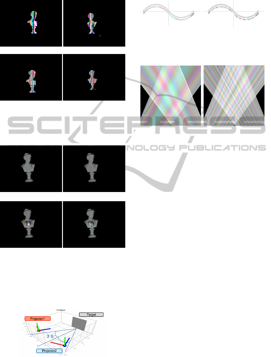
We next show the results from a sculpture. The
projection patterns for sculpture derived from our
method are shown in Fig.10. These patterns were
mixed on the sculpture. When the sculpture was
situated at the original position, the combination of
these patterns became white as shown in Fig.11 (a).
Figure11 (b) shows results when object shape was
changed partially. In this case, only small hemi-
sphere put on a sculpture was colored by the proposed
method as shown in (b). As shown in these figures,
the proposed method enables us to visualize change
in shape, even if the object shape is complex. Thus,
by applying our method, we can visualize defects of
products just by projecting coded lights.
4.3 Analysis
Finally, we analyze the properties of projection pat-
terns by using synthesized environment. In this ex-
periment, two projectors are set as shown in Fig.12.
The smooth curve was put at a target area as shown
(a) Projected result at initial position (basis shape)
(b) moved distance is 1.5cm
(c) with shape error
Figure 9: The result of 3D shape emphasis of cube. The
right images are results from pattern (a) which have low
frequency, and left images are results from pattern (b) which
have high frequency. At the initial point (basis shape), the
cube was colored in white. At the other points, the cube
was colored in various colors. When the object shape was
partially changed, just changed part was colored as shown
in (c).
in Fig.13. We projected high frequency and low fre-
quency patterns to the object respectively.
Figure13 (a) shows the results from low frequency
patterns, and Figure13 (b) shows the results from
hight frequency patterns. As shown in these figures,
the high frequency patterns provide us much clear vi-
sualization of shape difference. In these figures, the
basis shapes are colored in white, since the projected
lights are designed so that the basis shape are colored
in white. However, some points on the basis shape
was colored into non-white colors. This is because
the projector images are digitized in general, and pro-
jected pixels from two projectors do not overlap com-
pletely on the object surface.
Figure14 shows the cross-section of coloring in
the case of low frequency pattens (a) and high fre-
quency pattens (b). This figure indicates how the ob-
ject surface is colored in the space. It is not easy to
see, but a white basis shape exists at around the cen-
ter of the image, and no other points are colored into
white. Since the color changes drastically under high
3DObjectEmphasisusingMultipleProjectors
191
(a) Patterns derived from low frequency components
(b) Patterns derived from high frequency components
Figure 10: Projection patterns for sculpture shape emphasis:
Wavelength of upper pattern for R, G and B are 61pixel,
36pixel and 34pixel. Wavelength of lower pattern for R,G
and B are 47pixel, 21pixel and 17pixel.
(a) Projected result at initial position (basis shape)
(b) with shape error
Figure 11: The result of 3D shape emphasis of sculpture.
The right images are results from pattern (a) which have low
frequency, and left images are results from pattern (b) which
have high frequency. At the initial point (basis shape), the
sculpture was colored in white. When the object shape was
partially changed, just changed part was colored as shown
in (b).
Figure 12: Experimental environment
Basis shape
Moved Object
(a) Result under low frequency
patterns
Basis shape
Moved Object
(b) Result under high frequency
patterns
Figure 13: Basis shape and emphasized shape by low fre-
quency patterns (a) and high frequency pattens (b).
(a) Result under low frequency
patterns
(b) Result under high frequency
patterns
Figure 14: Cross-section of space coloring by low fre-
quency patterns (a) and high frequent pattens (b).
frequency patterns as shown in (b), small change in
shape of objects can be visualized in (b), while large
change in shape can be visualized efficiently under
low frequency patterns as shown in (a). Thus, the pro-
posed method can control the degree of difference in
shape extracted by the method by controlling the fre-
quency of projection patterns.
5 CONCLUSIONS
In this paper, we proposed a method for emphasizing
3D shapes just by projecting patterned light from mul-
tiple projectors. In our method, the patterned lights
are mixed up at the surface of objects, and the mix-
ture of multiple lights provides us image processing.
In particular, we proposed a method for extracting
and visualizing the difference in shape by projecting
coded lights. In this method, we do not need any com-
putation for image processing, since the image pro-
cessing is achieved by mixing lights projected from
multiple projectors. Furthermore, we do not need to
find image correspondences in order to obtain 3D in-
formation of objects. Thus, the proposed method does
not suffer from the wrong correspondence problem.
The efficiency of the proposed method was evaluated
by emphasizing 3D objects in the real scene. In our
future work, we extend our method form emphasizing
textured objects and moving objects.
VISAPP2014-InternationalConferenceonComputerVisionTheoryandApplications
192

REFERENCES
Gokturk, S. B., Yalcin, H., and Bamji, C. (2004). A time-
of-flight depth sensor - system description, issues and
solutions. In Proceedings of the 2004 Conference on
Computer Vision and Pattern Recognition Workshop
(CVPRW’04) Volume 3 - Volume 03, CVPRW ’04,
pages 35–.
Hartley, R. and Zisserman, A. (2000). Multiple View Geom-
etry in Computer Vision. Cambridge University Press.
Nakamura, R., Sakaue, F., and Sato, J. (2010). Emphasizing
3d structure visually using projection from multiple
projectors. In Proc. Asian Conference on Computer
Vision, pages 619–632.
Sakaue, F. and Sato, J. (2011). Surface depth computa-
tion and representation from multiple coded projec-
tor light. In Proc. IEEE International Workshop on
Projector-Camera Systems (PROCAMS2011), pages
75–80.
Seitz, S., Curless, B., Diebel, J., Scharstein, D., and
Szeliski, R. (2006). A comparison and evaluation of
multi-view stereo reconstruction algorithms. In Proc.
Conference on Computer Vision and Pattern Recogni-
tion.
Tomasi, C. and Kanad, T. (1992). Shape and motion
from image streams under orthography: a factoriza-
tion method. International Journal of Computer Vi-
sion, 9(2):137–154.
3DObjectEmphasisusingMultipleProjectors
193
