A Method of Eliminating Interreflection in 3D Reconstruction
using Structured Light 3D Camera
Lam Quang Bui
1
and Sukhan Lee
1, 2
1
Colleage of Information and Communication Enginerring, Sungkyunkwan University, Suwon, Korea
2
Department of Interaction Science, Sungkyunkwan University, Seoul, Korea
Keywords: Interreflection, Structured Light 3D Camera.
Abstract: Interreflection, which is one of main components of the global illumination effect, degrades the
performance of structured light 3D camera. In this paper, we present a method of eliminating interreflection
in 3D reconstruction using structured light 3D camera without any modification of the structured light
pattern. The key idea is to rely on the patterns in final layer of HOC (Hierarchical Orthogonal Coding),
where the effect of interreflection is weakest due to small light stripes in the pattern, to eliminate the
reflected boundaries as well as fill the missing boundaries in upper layers. Experimental results show that
the effect of interreflection in proposed algorithm is significantly reduced in comparison with original
decoding method of HOC. The proposed method can be readily incorporated into existing structured light
3D cameras without any extra pattern or hardware.
1 INTRODUCTION
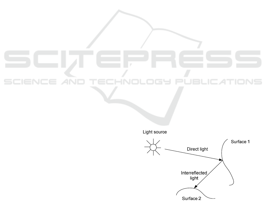
Interreflection is a process where the light from a
light source is reflected from an object and hits other
objects in the surrounding area, as shown in Figure
1. In 3D computer graphics, interreflection is an
important component of global illumination. In 3D
reconstruction using structured light based 3D
camera, interreflection causes the error in 3D
reconstruction of the surface where both
interreflection and direct light appear, thus removing
or identifying the interreflection has drawn much
attentions from computer vision community.
Forsyth et al. (Forsyth, 1989; 1990) are the
pioneers in studying the effect of interreflection and
its impacts on object shape reconstruction. The
analytic solution was presented and tested on
concave objects with varying albedo value. They
also demonstrated that the effect of interreflection
depends on the albedo of object surface, the same
object with smaller albedo value exhibits less
interreflections. This effect is caused by the non-
linearity of the m-bounced light with respect to the
surface albedo. However, the authors did not exploit
more on non-linearity property of m-bounced light
to remove the interreflection in shape recovery.
Instead, they claimed that the object shape can be
reconstructed by constructing a dictionary of the
most common interrefection can occur, and using
this dictionary to estimate object shape.
Figure 1: The direct light from light source hits the first
surface, then the reflected light hits the second surface,
which is called interreflection.
Drew et al. (Funt, 1993; Funt, 1991; Ho, 1990)
separated the interreflection from direct lighting by
using the color bleeding effect. However, they had
to make several assumptions depending on the scene
in order to apply their algorithm.
Nayar et al. (Nayar, 1991) solved the problem of
shape from interreflection by iteratively refining the
shape and reflectance. The algorithm starts to iterate
with the initial estimation of shape and reflectance in
the presence of the interreflection. The
640
Quang Bui L. and Lee S..
A Method of Eliminating Interreflection in 3D Reconstruction using Structured Light 3D Camera.
DOI: 10.5220/0004744906400647
In Proceedings of the 9th International Conference on Computer Vision Theory and Applications (VISAPP-2014), pages 640-647
ISBN: 978-989-758-009-3
Copyright
c
2014 SCITEPRESS (Science and Technology Publications, Lda.)

interreflection is estimated based on the
reconstructed shape and reflectance of the surface,
and in next iteration, this estimated interreflection is
compensated to compute the shape and reflectance.
In their follow-up work (Nayar, 1992), the authors
extended the algorithm to deal with colored and
multi-colored surfaces. Due to the fact that the
reflectance of a color surface point is dependent on
the incident light spectrum, the algorithm is applied
to the three chanels of color images independently.
However, their method can not handle occlusions.
The occluded part, which can add the interreflection
to the scene, is not considered at the time of
estimating the initial guess of the shape and
reflectance. A bad initial guess of the object shape
and reflectance could lead to the failure of
convergence of the algorithm.
Nayar et al. (Nayar, 2006) introduced a method
of separating the direct light from global light for
complex scenes using high frequency patterns. The
approach does not require the material properties of
the objects in the scene to be known. The key idea of
this method is to hide a small region of the scene
from illuminated pattern while keep other parts
illuminated. The intensity of the hided region is only
from global illumination. When all the points in the
scene hide once from illuminated light, they form a
global illumination map, from here the direct
illumination map is obtained by subtracting the
image, in which all regions are illuminated, with the
global illumination map. Even though the proposed
method can reduce the number of required images,
this number is still large (25 images are needed for
experiments), and the patterns should have
frequency high enough to sample the global
components.
Seitz et al. (Seitz, 2005) proposed to use inverse
light transport operator to separate m-bounced light
from a scene of arbitrary BRDF. The inverse light
transport operator is estimated under the assumption
of Lambertian surface.
In this paper, we proposed a new method to
eliminate the interreflected light components in 3D
reconstruction using HOC pattern (Lee, 2005), and
then the direct light component is used to reconstruct
the 3D point cloud of the scene. First, the one sided
edges of both direct and reflected light are estimated
in every captured pattern image. Second, the bottom
up approach is used to check and eliminate the
interreflected boundaries from layer 3 to layer 1.
Finally, the direct boundaries are used to reconstruct
3D point cloud of the scene.
The remainder of the paper is organized as
follows: In Section II, we describe our proposed
method to eliminate the reflected light component.
The experimental results are provided in Section III.
Finally, Section IV concludes the paper.
Figure 2: The appearance of interreflection together with
direct light. Where “1” is direct light region, “0” is the
surface region with no illuminated light, and “R” is the
reflected light.
2 THE PROPOSED METHOD
2.1 The Appearance of Interreflection
Together with Direct Light
When projector illuminating the pattern on the
scene, depending on the surface reflectance and
geometry, the interreflection might occur and appear
together with illuminated pattern in different ways,
as shown in Figure 2. The cases that can happen are:
The interreflection appears on the region without
illuminated pattern (Figure 2. a)
The interreflection appears within the region of
illuminated pattern (Figure 2. b)
The interreflection appears on the boundary of the
illuminated pattern (Figure 2. c-d)
The interreflection when illuminating the pattern
“1-0-1” appears edgewise on the region without
illuminated pattern (Figure 2. e), where “1” means
white pattern, and “0” means black pattern.
However, in reality the reflected light stripe
power can be weakened and the interreflection
can be unnoticeable depending the distance from
AMethodofEliminatingInterreflectionin3DReconstructionusingStructuredLight3DCamera
641
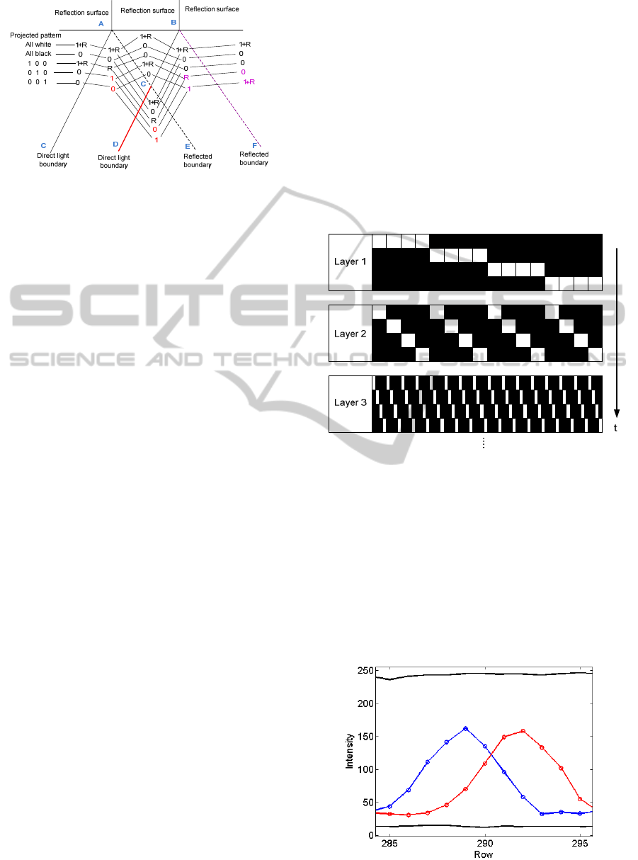
Figure 3: The model of the interreflection on the surface
together with direct light component.
interreflection source (reflection surface) to the
surface that interreflection appears. In this paper, we
exploit in detail the particular case described in
Figure
3. The reflection surface is the upper region,
and the interreflection reflected from reflection
surface appears on the lower region (“R”) together
with the illuminated pattern (“1”).
When different patterns are projected, as shown
in
Figure
3, the boundaries can be recovered or not
depending on the strength of the reflected light
compared with direct light stripe, here we consider
the boundaries formed by the intersection between
signal “1-0” and “0-1”.
Boundary “AC”: if the intensity of “R” is lower
than that of “1” then “AC” can be detected by pairs
“1+R-R” and “0-1” from patterns “1 0 0” and “0 1
0”, otherwise “AC” cannot be detected
Boundary “DC” is always detected by pairs “1-0”
and “0-1” from patterns “0 1 0” and “0 0 1”, so
called direct boundary
Boundary “AC” can be detected by pairs “R-0”
and “1-1+R” from patterns “1 0 0” and “0 1 0” if
the intensity of “R” is lower than that of “1”
Boundary “CB” can be detected by pairs “1+R-R”
and “0-1” from patterns “0 1 0” and “0 0 1” if the
intensity of “R” is lower than that of “1”
Boundary “CE” is always detected by pairs “R-0”
and “0-R” from patterns “1 0 0” and “0 1 0”, so
called reflected boundary
Boundary “BF” can be detected by pairs “R-0” and
“1-1+R” from patterns “0 1 0” and “0 0 1” if the
intensity of “R” is greater than that of “1”
2.2 Hierarchical Orthogonal Coded
Patterns
In this paper, we use HOC (Hierarchical Orthogonal
Coding) structured light patterns developed by Lee
et al. (Lee, 2005), in which the orthogonal codes are
arranged hierarchically in order to reduce the length
of codes. The length f of code is divided into a few
layers L. Each layer includes H orthogonal codes
recursively as shown in Figure 4. Although the
signal codes in the HOC are not orthogonal, each
layer has a set of orthogonal codes. For more details,
please refer to (Lee, 2005).
For example, we assume that a HOC has four
layers (L=4) and the number of orthogonal codes in
each layer is also four (H
1
= H
2
= H
3
= H
4
= 4). In
this case, the total number of signal codes is 256 (H
1
x H
2
x H
3
x H
4
= 256) and the code length is 16 (H
1
+ H
2
+ H
3
+ H
4
= 16), i.e. we need 16 camera images
for decoding addresses of the signals.
Figure 4: Hierarchical Layer of Code. Each layer consists
of 4 patterns, each code in upper layer is divided in to 4
sub-codes in lower layer.
2.3 Interreflection Elimination
Algorithm
2.3.1 Boundary Detection by Intersection
The most common way to obtain sub-pixel accuracy
boundary position is to calculate the intersecting
point between the signals of pattern “1-0” and its
inverse “0-1”, as shown in Figure 5.
Figure 5: The boundary is detected from the intersection
of pattern signal “1-0” and “0-1”.
VISAPP2014-InternationalConferenceonComputerVisionTheoryandApplications
642
2.3.2 One Sided-edge Boundary Detection
Due to the fact that not all boundaries, including
direct and reflected boundaries, can be detected by
signal intersection method, moreover the direct or
reflected light stripes contains all the information of
the edges even they overlap each other, we can
search for all possible boundaries from the edge of
direct or reflected light stripes. To detect the
boundary from one sided-edge, we compute the first
order derivative of the edge signal, and then detect
boundary by searching for the peak of the derivative,
as illustrated in Figure 6. In practice, the first order
at position i
th
is computed by following equation:
() ( ) ( )df i f i d f i d
where 2*d is step to compute derivative.
In order to avoid local peak, a window search
with size of 7 pixels was used to find the peaks of
the derivative.
132 134 136 138 140 142 144
0
50
100
150
200
Row
Intensity
Edge signal
First derivative
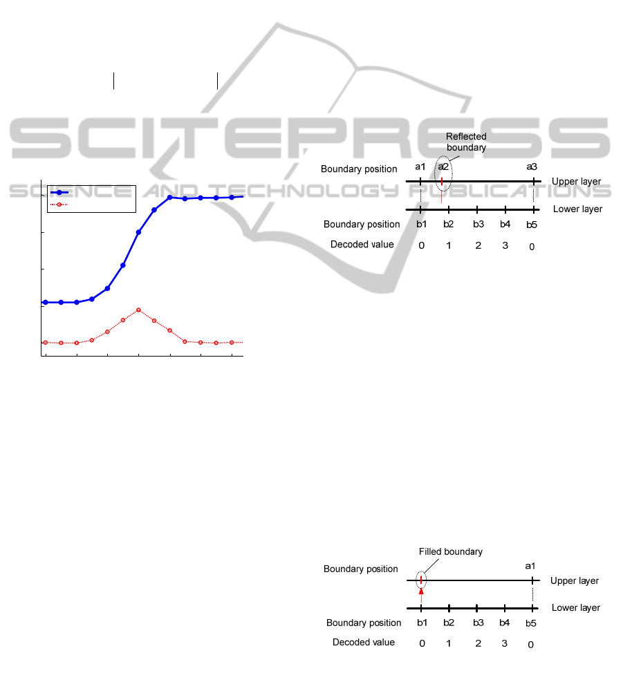
Figure 6: The signal of an edge and its first order
derivative.
2.3.3 Interreflection Elimination
The HOC patterns described in Section 3 have four
layers, and the width of stripes in lower layer is four
times narrower than that in upper layer, thus the
power of the light stripe in lower layer is four times
less than that in upper layer; the light stripes in last
layer patterns have weakest power, consequently the
interreflection caused by this layer patterns is
weakest and the interreflection distorts the direct
boundaries very little. In other words, the
interreflection affects on direct light component is
mainly in region from AB to C in
Figure
3, and this region is minimized in last layer.
Since last layer has smallest light stripes, we
cannot do any further correction for this layer, thus
by assuming that all boundaries in last layer patterns
of HOC are correct, we can use them to eliminate
interreflected boundaries and correct or fill the
missing direct boundaries in upper layers using
bottom up approach.
Eliminating reflected boundary:
Once the boundary map of layer 4 (last layer) is
computed by intersection, and boundary maps of
other layers (from layer 1 to 3) are also computed
from one-sided edges, we start to compare
boundaries in pairs of layer i (lower layer) and layer
i-1 (upper layer), start from layer 4. If a boundary in
upper layer does not match with any boundary
having decoded value “0”, then that boundary is
classified as either reflected boundary or noise and
rejected. As shown in Figure 7, boundary “a2” in
upper layer does not match with “b1” or “b5” in
lower layer, so it is rejected.
Figure 7: One direct boundary in upper layer should match
with one boundary in lower layer having decoded value
“0”, otherwise it is either reflected boundary or noise.
Filling the missing direct boundaries in upper
layer:
Since boundary maps from layer 1 to layer 3 are
detected using on-sided edges, there are chances that
boundaries are not detected, these missing
boundaries in one layer can be filled from the lower
layer, such as filling boundaries from layer 4 to layer
3, then from layer 3 to layer 2, and finally from layer
2 to layer 1. The rule to fill boundary is described in
Figure 8: search for the boundary in lower layer
having decoded value “0”, if there is no matched
boundary in upper layer, then insert that boundary to
the upper layer.
Figure 8: If one boundary in lower layer having decoded
value “0” does not have any matched boundary in upper
layer, fill that boundary to upper layer.
AMethodofEliminatingInterreflectionin3DReconstructionusingStructuredLight3DCamera
643
After filling the boundaries from lower layer,
these new boundaries are assigned new decoded
values according to theirs neighbor boundaries along
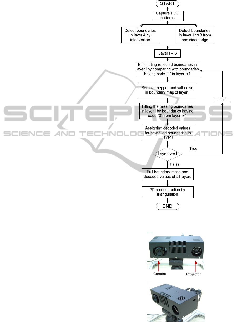
the edge of light stripe. The algorithm describing the
steps of removing reflected boundaries as well as
recovering direct boundaries is illustrated by
flowchart in Figure 9.
3 EXPERIMENTAL RESULTS
3.1 Experimental Setup
The proposed method has been implemented in a
light weight structured light system which can be
used for service robot applications. The system
consists of an Optoma PK301 Pico projector, a PGR
Flea2 1394 digital camera mounted a TV LENS
12mm 1:1.3 and a computer, as illustrated in Figure
10. The resolution of the projector was 800 x 600
pixels and that of the camera was 640 x 480 pixels.
The position of the camera was about 13cm to the
right of the projector. The computer generates signal
patterns, acquires images, and computes depth
images. The system has been calibrated in prior.
3.2 Results
To evaluate the proposed method, we capture the
images of projected HOC patterns on the scene
where the interreflection occurs, an example of
captured HOC pattern is shown in Figure 11.
First, the boundary map of layer 4 is computed
by intersecting the stripe edge signals in pairs of
consecutive patterns in that layer, as depicted in
Figure 12. Since layer 4 has finest stripe patterns,
there is no further information of direct boundaries
to be used for correcting the interreflection effects in
this layer, thus the errors caused by interreflection
cannot be corrected for this layer, as shown in the
horizontal band in the middle of Figure 12.
Second, the boundary maps of layers from 3 to 1
are estimated by on-sided edge in each layer, as
shown in Figure 13. (a); since the boundaries are
detected by searching for the edges of stripe pattern,
both direct and reflected boundaries are detected.
Since HOC patterns have a property that each
boundary in upper layer has a common boundary in
lower layer having decoded value “0”, we are using
this fact to remove reflected boundaries as well as
noise. The reflected boundaries in layer 3 are first
eliminated by comparing with the common
boundaries in layer 4, the salt and pepper noise is
then once more removed by a simple running
Figure 9: The flow chart of interreflection eliminating
algorithm.
Figure 10: The setup of the structured light system.
VISAPP2014-InternationalConferenceonComputerVisionTheoryandApplications
644
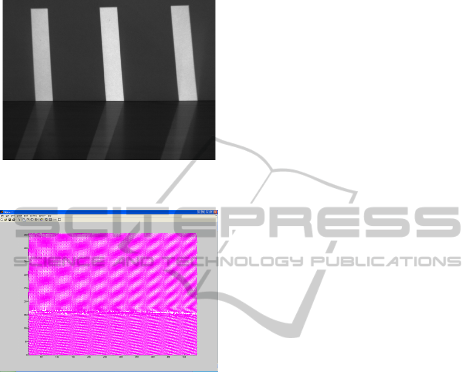
Figure 11: A captured HOC pattern in layer 2, the upper
region is the source of reflection, and the interreflection
appears on the lower region.
Figure 12: The boundary map of layer 4 detected by
intersection.
window size 3x3. Now the boundary map of layer 3
remains only direct boundaries, but some of them
are missing, as illustrated in Figure 13. (b) right. To
fill the missing direct boundary in layer 3, we search
for the common boundaries (having decoded value
“0”) in layer 4 and insert to boundary map of layer
3. Each boundary, that has been filled to layer 3, is
assigned with decoded value of the neighbor
boundaries along the light stripe. Repeat these
processes of removing reflected boundaries and
noise, and filling the missing direct boundaries for
layer 2 and layer 1, we have final direct boundary
maps of layer 1 to 3, as shown in Figure 13. (c).
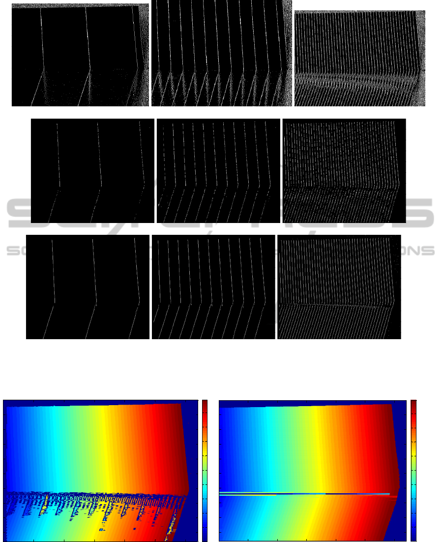
Finally, the boundary maps of layer 1 to layer 4
together with their decoded value maps are used to
decode the projector correspondence map of the
scene by following the decoding algorithm of HOC
(Lee, 2005), the final projector correspondence map
is shown in Figure 14
(b). As can be seen, the region
affected by interreflection in the result of proposed
method is significantly reduced in comparison with
the result of original decoding method of HOC
(Figure 14
(a)). However, there is a small band in
the middle of correspondence map in Figure 14 (b)
where the interreflection cannot be removed, since
there is no further correct information of direct
boundary to correct for layer 4. Figure 15 and Figure
16
show the 3D point clouds of the scene
reconstructed from the projector correspondence
maps produced by proposed method and original
HOC method respectively. The holes and outliers
are created by effects of interreflection, they confirm
the discussion above.
4 CONCLUSIONS
We have presented a new method to eliminate the
interreflection effects in 3D reconstruction using
structured light 3D camera endowed with HOC
patterns. The proposed method first detects both
direct and reflected boundaries in layer 1 to layer 3
from one-sided edges, and boundaries in layer 4 by
intersection. Then the boundaries in last layer are
used to eliminate the reflected boundaries in upper
layers, as well as filling the missing boundaries. The
experimental results have shown that the effect of
interrerflection on 3D reconstruction in proposed
method is greatly reduced in comparison with
original decoding method of HOC. However, there
is a small band region that the interreflection cannot
be removed, since there is no further direct boundary
information to eliminate the reflected boundary in
last layer of HOC. And this drawback is the main
issue for our near future work.
ACKNOWLEDGEMENTS
This research was performed for the KORUS-Tech
Program (KT-2010-SW-AP-FSO-0004) funded by
the Korea Ministry of Science, ICT and Planning
(MSIP). This work was also supported in part by
research program funded by MSIP, Korea under
ITRC NIPA-2013-(H0301-13-3001), and in part by
NRF-2013M1A3A02042335, the Ministry of
Science ICT and Future Planning, Korea.
AMethodofEliminatingInterreflectionin3DReconstructionusingStructuredLight3DCamera
645
(a)
(b)
(c)
Figure 13: The boundary maps of layer 1 (left), layer 2 (middle), and layer 3 (right) detected from one-sided edge. a) The
original detect boundary maps from one-sided edge. b) The boundary maps after discarding reflected boundaries and
filtering the salt and pepper noise. c) The boundary maps after filling the missing boundaries from lower layer.
0
20
40
60
80
100
120
140
160
180
0
0
0
0
0
0
0
0
0
0
20
40
60
80
100
120
140
160
180
(a) (b)
Figure 14: The projector correspondence maps of the scene decoded by original method HOC (a) and the proposed method
(b).
VISAPP2014-InternationalConferenceonComputerVisionTheoryandApplications
646
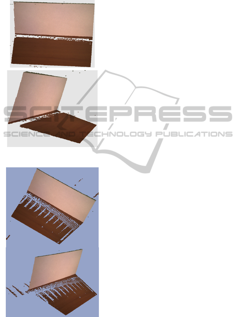
Figure 15: The 3D point cloud of the scene reconstructed
by proposed method in different views.
Figure 16: The 3D point cloud of the scene reconstructed
by original decoding method of HOC in different views.
REFERENCES
D. Forsyth and A. Zisserman, 1989. Mutual illumination.
Computer Vision and Pattern Recognition.
D. Forsyth and A. Zisserman, 1990. Shape from shading
in the light of mutual illumination. Image and Vision
Computing.
B. V. Funt andM. S. Drew, 1993. Color space analysis of
mutual illumination. IEEE Transactions on Pattern
Analysis and Machine Intelligence.
B. V. Funt, M. S. Drew, and J. Ho, 1991. Color constancy
from mutual reflection. International Journal of
Computer Vision.
J. Ho, B. V. Funt, and M. S. Drew, 1990. Separating a
color signal into illumination and surface reflectance
components: Theory and applications. IEEE
Transactions on Pattern Analysis and Machine
Intelligence.
S. Nayar, K. Ikeuchi, and T. Kanade, 1991. Shape from
interreflections. International Journal of Computer
Vision.
S. Nayar and Y. Gong, 1992. Colored interreflections and
shape recovery. In DARPA Image Understanding
Workshop (IUW), pages 333–343.
S. Nayar, G. Krishnan, M. Grossberg, and R. Raskar,
2006. Fast separation of direct and global components
of a scene using high frequency illumination. In
Proceedings of ACM SIGGRAPH.
S. Seitz, Y. Matsushita, and K. Kutulakos, 2005. A theory
of inverse light transport. In International Conference
on Computer Vision.
S. Lee, J. Choi, D. Kim et al., 2005. Signal Separation
Coding for Robust Depth Imaging Based on
Structured Light. Proceedings of the IEEE
International Conference on Robotics and
Automation, pp. 4430-4436.
AMethodofEliminatingInterreflectionin3DReconstructionusingStructuredLight3DCamera
647
