
Priority Enabled Distance-energy based Routing Algorithm
for UWSN
C. P. Gupta
1
, Mayank Bisht
1
and Arun Kumar
2
1
Department of Computer Engineering, Rajasthan Technical University, Kota, India
2
Department of Mathematics, Government College, Kota, India
Keywords: UWSN, Routing, Acoustic Signal, Routing Factor, Energy Scale Value, Priority Packets.
Abstract: Underwater Sensor Networks (UWSNs) are being deployed for range of applications like collection of
oceanic data for research, military surveillance, disaster prevention, underwater exploration etc.
Characteristics such as use of acoustic signal for communication, 3D deployment, and higher losses make
routing in UWSNs different from terrestrial sensor networks. In this paper, we present a location aware
routing algorithm based on routing factor (Rf); a function of distance and energy. In our proposed
algorithm, forwarding node is selected by sender amongst its neighbors depending on their distance from
destination node and residual energy. To consider energy with distance, Energy scale value (Es) is used as a
scaling range. Priority packets are also used for quick delivery of packets. Simulation results show improved
performance of our routing algorithm in terms of network lifetime and end to end delay.
1 INTRODUCTION
Underwater Sensor Networks (UWSNs) provide
huge potential for development & utilization of
underwater resources. Sensor nodes & Autonomous
Underwater Vehicles (AUVs) are envisioned to find
application in the exploration of underwater regions
for environmental monitoring, intrusion detection &
surveillance, mine detection, assisted navigation,
underwater exploration and seismic sensing (Hied.
et al, 2012). But these potential applications are
viable only if we have efficient underwater
communication system.
Characteristics of UWSNs differ from terrestrial
WSNs in terms of communication methods, network
deployment and protocols etc (Davis and Chang,
2012). Since radio waves suffer from high
attenuation in water, acoustic signals are used for
communication in UWSNs. This renders terrestrial
routing techniques unsuitable for UWSNs. UWSNs
also suffer from high delays, transmission losses and
node mobility due to water currents, which may
result in loss of connectivity and node failures
(Manjula et al., 2011). Routing protocols designed
for sensor networks are based on characteristics such
as type of signals used, available power &
bandwidth, delays, losses, node deployment (Zaihan,
2008). However, advancement in semiconductor
technology have overcome limitations of processing
speed, storage in UWSNs, still underwater
deployments occur over shorter periods (several
days), rather than months or years common in
terrestrial sensing. Efficient Routing techniques can
improve the lifetime of the network.
In this paper, we propose a routing algorithm that
considers both distance and energy of nodes for
making routing decisions in a 3-dimensional UWSN.
The proposal is a location based algorithm in which
all nodes are aware of their position in the network.
Routing decision is taken by the sender based on
Routing factor (Rf); a function of neighbour’s
distance to sink and its residual energy. High priority
packets are routed differently ensuring lower end to
end delay. Routing tables are used to reduce packet
transmissions among nodes and hence improve
performance. Our simulations show improvement in
lifetime & network throughput with satisfactory end
to end delays.
Rest of the paper is organized as follows. In
Section 2, we will review some existing routing
protocols for UWSNs. Section 3 describes our
proposed routing algorithm. Performance evaluation
of the proposed algorithm is presented in section 4.
Finally conclusions are drawn in Section 5.
133
P. Gupta C., Bisht M. and Kumar A..
Priority Enabled Distance-energy based Routing Algorithm for UWSN.
DOI: 10.5220/0004759001330138
In Proceedings of the 3rd International Conference on Sensor Networks (SENSORNETS-2014), pages 133-138
ISBN: 978-989-758-001-7
Copyright
c
2014 SCITEPRESS (Science and Technology Publications, Lda.)

2 RELATED WORK
Vector Based Forwarding (VBF) (Xie et al., 2006) is
a location based routing protocol involving only a
fraction of nodes in routing. Packets are forwarded
along a virtual tunnel from source to sink. A self
adaptation algorithm for adjusting the forwarding
policy based on node density was also proposed.
The algorithm introduces desirableness factor in the
range of (0, 3) to measure the suitability of a node to
forward packets. Received packet is held by the
node for a time period related to its desirableness
factor, such that node with less desirableness factor
will forward the packet earlier. However, redundant
packet transmissions and packet delays cause energy
losses requiring alternate measures.
Focused Beam Routing (FBR) protocol (Jornet et
al., 2008) uses a distributed approach, in which route
is dynamically established as the data packet
traverses the network towards its final destination.
For finding all the nodes in a cone with ±θ/2
emanating from the source nodes towards the
destination nodes at the minimum distance, a
Ready_To_Send (RTS) signal with minimal energy
is transmitted. In case, no node responds through a
Clear_To_Send (CTS) like packet, the power level
and if required also value of θ is varied. The node
closer to final destination is selected as the relay
node for the next hop. However, performance of
algorithm is heavily dependent upon collision of
CTS packets at the source of RTS. End to end Delay
is also high in FBR.
Depth Based Routing (DBR) (Yan et al., 2008)
requires only local depth information against the full
location information required in VBF. DBR
assumes multiple sinks deployed at the surface
communicating with each other & Base Station
through radio links. Each packet in DBR contains
the depth information. On receiving a packet, node
forwards it only if it is closer to sink i.e. situated at
lower depth than sender node. Priority queue
mechanism is used to reduce the number of
forwarding nodes transmitting the same packet.
Each node receiving the packet compute packet
holding & scheduled sending time based on its depth
such that the node at lower depth transmit the packet
earlier than node at a larger depth. The algorithm
requires synchronization of clocks to ensure that
scheduled sending time is computed correctly by all
the nodes. Also, it requires specific deployment with
sink nodes floating on water surface.
An Energy Efficient Localization free Routing
Protocol named EEDBR proposed by Wahid et al.,
2012 also utilizes the depth of sensor nodes for
forwarding data packets along with the residual
energy of sensor nodes to improve the network
lifetime. Sender node enquires depth information
among its neighbours and according to their depths
create prioritized node list. On receiving packet,
each node holds the packet for some time on the
basis of its priority in the priority list. The EEDBR
results in improved network lifetime, energy
consumption and end-to-end delays and offers
comparable delivery ratio. However, the proposed
algorithm requires sorting for assigning priorities
which require more storage and computing power
within the sensor nodes. Also it requires specific
deployment with sink nodes floating on water
surface.
SBR-DLP (Sector-Based Routing with
Destination Location Prediction), proposed by
Chirdchoo et al., 2009 is also a location based
routing protocol for UWSN. SBR-DLP assumes sink
node to be mobile with pre-planned path and
schedule known to all other nodes in the network.
The whole range of node is divided into a number of
sectors. The sectors are prioritized based on angular
differences from the virtual vector SD from the
sender S to Destination D. Then according to sector
priority, the node closest to predicted location of the
mobile sink is selected as forwarder node. Latest
network information is acquired each time before
sending a packet using chk_ngb & chk_ngb_reply
packets. Limitations of this algorithm include large
delay between the packets due to
chk_ngb/chk_ngb_reply packets.
More routing techniques for UWSN are
discussed in (Wahid et al., 2010). Unlike location
unaware routing algorithms DBR and EEDBR, our
proposal does not require sinks to be floating on the
surface. Our algorithm works even if the sink is
mobile or at distant region of network deployment.
3 PROPOSED ALGORITHM
In our algorithm, routing decision depends on the
amount of residual energy of the neighbour node and
its distance from the destination node. Sender
decides the next forwarder node from its neighbours
and unicasts the packet to that node. Thus, our
algorithm attempts to route the packet through a
node which balances energy consumption in the
neighbouring nodes while maintaining acceptable
packet delay and delivery ratio. This avoids
selecting a certain node or group of nodes every
time to forward a packet. UWSN characteristics
such as 3-D network architecture, node mobility,
SENSORNETS2014-InternationalConferenceonSensorNetworks
134

acoustic channels, and limited power availability
have been taken into consideration in our proposal
Following assumptions have been made while
designing the algorithm:
Each node knows its location. It is required as the
proposed algorithm location based routing
algorithm (Vijay and Choo, 2006).
Sinks are mobile and are equipped with
navigational and propelling system (as like an
Autonomous Underwater Vehicle). The
trajectory of sinks is pre-planned and is known to
all the nodes in the network. Sinks are allowed to
deviate from the trajectory only within a range.
All nodes other than sink node(s) have random
walk dynamic mobility pattern.
3.1 Packet Formats
Three types of packets namely; Hello, Ack and
Routing are used in our proposal. Hello Packet is
broadcasted by a node to enquire about its
neighbouring nodes in the network. Ack packet is
sent by a node in reply to Hello packet. After
receiving Ack, nodes update their neighbour table
with the information contained in this packet.
Routing Packet contains information about the
packet and data to be sent from source to sink node.
Priority_Bit sets priority with which packet is to be
sent by the sender. It is 1 for priority packet and 0
for normal packet. The packet formats are shown in
Fig 1.
Sender_Id
(10)
Position
(36)
Residual
Energy(16)
Broadcast
address (10)
(a) Hello Packet (72 bit)
Sender
Id (10)
Position
(36)
Residual
Energy(16)
Unicast
address (10)
(b) Ack Packet (72 bit)
Source
Id (10)
Forwarder
Id(10)
Sink
Id(10)
Packet_Sequence
Number(15)
Priority
Bit (1 )
Data
(c) Routing Packet (4800-bit )
Figure 1: Packet Formats.
3.2 Routing Tables
Two tables are maintained by each node to minimize
exchange of control packet (Hello and Ack), speed
up packet transmission and reduce end to end
delays.
(a) Neighbour Table: Neighbour table holds
information of neighbours which is updated
whenever the node has a packet to forward and is
supposed to be stable for a predetermined duration
based on intensity of water currents. Higher duration
is set for networks deployed in still water. The
neighbour table has the following structure
<Neighbour_Id, Position, Residual_Energy>
(b) Sink Table: Sink table holds the information of
the sinks deployed in the network. It also stores
information related to previously taken path by a
packet from that node to each sink listed in table.
The sink table stores the following information:
<Sink_Id, Position, Fwd_Id_nomal, Lf
n
, Fwd_Id_priority,
Lf
p
>
Sink_Id and Position represents the position of sink
node; Fwd_Id_normal & Fwd_Id_priotity represents
the previous forwarder’s Id in normal and priority
modes; Lf
n
& Lf
p
are the time intervals called
lookup factor for the validating the suitability of
sending current packet through previous forwarder
node to sink node.
Algorithm: Distance Energy based Routing
Algorithm with Priority Handling.
At Each Node:
1. If nbr_table == empty() OR t
nbr_upd
is expired
Create nbr_table
i. Broadcast Hello packet
ii. Analyze Ack packets replied by nodes.
iii. Update nbr_table , t
nbr_upd
& d_thresh.
2. If a node has packets to send/forward
i. Create packet, set sink_id and priority.
ii. In sink_table against the sink_id and
packet_priority check Lf
iii. If ‘Lf ’ is not expired OR ‘Lf ’ ! = NULL
a. Schedule the packet for forwarding using
previous forwarder node in sink_table.
iv. If ‘ Lf ‘ is expired then
a. Calculate the Rf for each neighbour node
b. Select node with minimum Rf value as
forwarder node to send packet
c. Schedule the packet for forwarding.
d. Update sink_table
3. If a node receives a packet
i. If Hello packet then reply with a Ack packet
ii. Else if routing packet then
a. Extract source and sink information.
b. If node_Id == sink_Id then
i. Receive the packet
c. Else forward packet by following step 2.
3.3 Design of Algorithm
Design factors and elements of our algorithm are
discussed below:
(a) Routing Factor (Rf) and Energy Scale Value
(Es): Routing Factor (Rf) is computed by sender
PriorityEnabledDistance-energybasedRoutingAlgorithmforUWSN
135

node on the basis of distance between its neighbour
& sink and neighbour node’s residual energy such
that the most suitable node for forwarding the packet
has minimum Rf. Energy Scale Value (Es) is
scaling range for node’s residual energy to
commensurate it with distance for computing Rf.
Let, Distance between neighbour & destination
node = dist(n,d),
Energy Scale Value = Es,
Current residual energy level = E
res
Energy Difference or Initial Energy = E
diff
Then, Routing factor is given by:
Rf = dist(n,d) + Es * ( 1- E
res
/E
diff
) (1)
This is the Rf for forwarding a normal packet. While
forwarding a priority packet, ‘Es’ is assumed to be
0. ‘I’ plays a major role in balancing the energies of
candidate forwarding nodes. It adds up an extra
value to Rf against node energy to make the routing
decision dependent on energy also.
Fig.2 illustrates routing decision based on Rf.
Distance d
i
is distance of destination node D to
neighbour node i and ed
i
is scaled value of energy of
neighbour nodes. Value of ed
i
is less for node having
high residual energy. From (1) we have Rf as the
sum of d
i
and ed
i
. The node with minimum Rf is
selected as next forwarding node by sender S.
Figure 2: Illustration of routing decision.
In above figure, neighbour node 2 has minimum
distance d
i
but less energy (as ed
i
is large) while
node 3 has more distance d
i
and more energy (as ed
i
is small). The overall Rf is less for node 2 hence,
node 3 is selected as forwarder. For a priority packet
as only distance is considered for computing Rf so
node 2 will be selected for forwarding the packet.
(b) Distance Threshold (d_thresh) and Packet Burst
Size (bs): Distance threshold is a function of time
used to cancel out the motion effect of nodes that
may move out of the range of sender before t
nbr_upd
expires. Whenever t
nbr_upd
is set, value of d_thresh is
set to minimum value. As the time progresses,
d_thresh increases. “d_thresh” is the maximum
motion of nodes after ‘t’ units of time. For finding
suitable forwarder then, node decreases its range by
d_thresh. Packets are generated by nodes in burst of
1 to 4 packets depending on size of information to
be sent. Packet can be generated by any node in the
network (except sink node).
(c) Priority handling and Routing Decision: Routing
decision is taken by the source or intermediate
sender node itself depending on type of packet, by
accessing the neighbour information in neighbour
table or previous forwarder information in sink
table. The packets can be forwarded as normal or
priority packet as decided by source. Priority packets
is an arrangement of sending packet with minimum
end to end delay by considering only distance
information for urgent information. Priority packets
are not targeted to balance energy and are given
priority among other packets at each node in the
network.
(d) Packet Acknowledgements: Acknowledgements
can be carried out in two ways. First way is to use
acknowledgements from sender node and forwarder
node in a hop by hop fashion. Secondly, we can use
packet acknowledgement from sink node to source
node on successful delivery of packet. Size of these
acknowledgements is very small so they can be
easily used in the network and can even be
piggybacked by other packets. However, due to
node motion, it is difficult to provide second type of
acknowledgements. Hence, we use hop by hop
acknowledgements to ensure successful delivery of
packets.
4 RESULTS AND ANALYSIS
We simulated our routing algorithm on a simulator
program created in C++ and use aqua3d animator to
visualize the simulations and working of our
algorithm (Tran, 2009). Simulations were performed
a large number of times and the results were
averaged from all results. Table 1 list the parameters
used in our simulations. For evaluation of our
proposed routing algorithm, we use following
performance metrics.
Lifetime: Network Lifetime is the time before first
node die in the network. We considered lifetime as
the time until a number of nodes die in the network.
End to End Delays: It is the time taken by a packet
to reach from source node to destination/sink node.
Packet Delivery Ratio: It is the ratio of number of
unique packets successfully delivered at the sink
SENSORNETS2014-InternationalConferenceonSensorNetworks
136
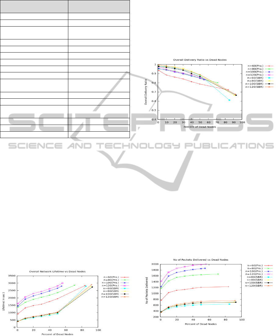
Table 1: Simulation Environment.
SIMULATION
SETTING
VALUE
Node Deployment Area 1000 x 1000 x 600 m
3
Deployment Type Random deployment
Node Speed
1 to 3 m/sec (random
direction)
Modem Type Acoustic Modem
Antenna Type Omni-directional
Transmission Range 300 metres
Data Rate 15000 bps
Speed of Sound 1500 m/sec
Size of Data Packet 4800 bit
Size of Control Packets
(Hello & Ack)
72 bit
Energy Scale Value 300
Packet Burst Size 1 to 4 packets
Neighbour Update Time
(t
nbr u
p
d
)
4 sec
Lookup Factor (Lf
n
& Lf
p
) 2 sec
Number of Sink Nodes 6
Number of Total Nodes Variable ( 60 to 120)
4.1 Performance Evaluation
(a) Lifetime: We evaluated lifetime of the network
against percent of nodes dead in the network for
both the proposed routing scheme and SBR-DLP..
Comparison of overall lifetime in both the routing
schemes is shown in Fig 3. We observe an increase
in lifetime by a factor of 2 with respect to SBR-
DLP. This is because SBR-DLP always enquires
about neighbouring nodes before sending a packet
hence nodes die soon (Chirdchoo et al., 2009). Our
routing technique employs balanced energy
consumption and thus improves network lifetime.
The lifetime of SBR-DLP does not much deviate
even after increase in node density as the number of
transmissions to find neighbour nodes also
increases.
Figure 3: Comparison of Overall Lifetime with SBR-DLP
(b) Packet Delivery Ratio: Comparison of overall
PDR in both schemes is shown in Fig. 4 below.
Overall PDR decreases rapidly as the dead
nodes increase in the network. At lower network
densities, delivery ratio of SBR-DLP is much higher
than our proposed routing. However, at high
densities we observe a comparable overall PDR in
both the routing schemes. SBR-DLP performs well
in case of PDR than our routing because it utilizes
latest network information while performing but it
costs more energy usage and hence the lifetime of
the network (Chirdchoo et al., 2009).
Figure 4: Comparison of Overall PDR with SBR-DLP.
However, number of packets actually delivered
should also be considered before accounting for
higher delivery ratio in SBR-DLP. Because more the
number of packets send, higher are the chances of
packet loss, hence lesser delivery ratio. Fig. 5 shows
packets delivered in both routing schemes. Number
of packets delivered increases with increase in
network density. In our routing scheme number of
packets delivered is much more compared to that in
SBR-DLP. In SBR-DLP, energy drains out in
successive transmissions in finding network
information before sending each packet. Increase in
number of packets generated and delivered
decreases the delivery ratio in our proposed routing
algorithm.
Figure 5: Comparison of Number of Packets delivered
with SBR-DLP.
(c) Overall End to end Delay: E2E Delay in both the
routing schemes is shown in Fig 6. We observe
comparable delays in both the routing schemes. At
PriorityEnabledDistance-energybasedRoutingAlgorithmforUWSN
137

adequate node densities our algorithm performs
better than SBR. However, at low densities, due to
inadequate routing options we observe some
increase in end to end delay. Also, delays are
dependent on node motion and neighbor density
which can be highly unpredictable at times.
Figure 6: Comparison of Overall Average E2E Delay with
SBR-DLP.
5 CONCLUSIONS AND FUTURE
WORK
Energy efficiency is one major issue in UWSNs. In
this paper we proposed distance energy based
routing algorithm which improves the lifetime of
underwater networks by utilizing location and
residual energy information to route a packet.
Simulation results shows that the proposed routing
algorithm improves the network lifetime with
satisfactory packet delivery ratio and end to end
delays. Also it has the priority concerns for a packet
which allow the packet to be forwarded with the
shortest path possible with high priority and minimal
waiting time. The simulation results are analysed on
various performance metrics and the results were
satisfactory.
Our routing algorithm needs to be developed
further so that it complies with optimality
constraints on Energy Scale and mobility. Complex
routing scenarios like void prevention, looping of
data packets, packet collisions also need to be
addressed. Other improvements include minimizing
overheads, increase channel utilization, self
configuring nodes, incorporating the localization
algorithm as a part of routing algorithm. Developing
this algorithm as a part of open source software like
NS2 will make it susceptible with networking
standards.
REFERENCES
Chirdchoo, N.; Wee-Seng Soh; Kee Chaing Chua, 2009,
“Sector-Based Routing with Destination Location
Prediction for Underwater Mobile Networks”, IEEE
international conference on Advanced Information
Networking and Applications, WAINA’09, pp. 1148-
1153, 2009.
Davis, A.; Hwa Chang; 2012, "Underwater wireless sensor
networks," Oceans, 2012, vol., no., pp.1-5, 14-19,
Heidemann, John, et al, 2012 "Underwater sensor
networks: applications, advances and challenges."
Philosophical Transactions of the Royal Society A:
Mathematical, Physical and Engineering Sciences
370.1958: 158-175.
Jornet, Josep Miquel, Milica Stojanovic, and Michele
Zorzi; 2008, "Focused beam routing protocol for
underwater acoustic networks.", Proceedings of the
third ACM international workshop on Underwater
Networks. ACM, 2008.
Manjula.R.B, Sunilkumar S. Manvi, 2011, “Issues in
Underwater Acoustic Sensor Networks ”, International
Journal of Computer and Electrical Engineering.
Tran, Matthew T., 2009, “Aqua3D: Three-Dimensional
Animator for Underwater Sensor Networks”,
University of Connecticut, 2009.
Vijay Chandrasekhar, Yoo Sang Choo, 2006,
“Localization in Underwater Sensor Networks –
Survey and Challenges” In proc. of WUWNet’06, Los
Angeles, California, USA, September 2006.
Wahid, A; Dongkyun, Kim; 2010, “Analyzing Routing
Protocols for Underwater Wireless Sensor Networks”,
International Journal of Communication Networks and
Information Security (IJCNIS) , December 2010.
Wahid, A; Dongkyun, Kim; 2012, “An Energy Efficient
Localization-Free Routing Protocol for Underwater
Wireless Sensor Networks,” International Journal of
Distributed Sensor Networks, vol. 2012,
Xie, Peng, Jun-Hong Cui, and Li Lao. 2006, "VBF:
vector-based forwarding protocol for underwater
sensor networks." Networking 2006. Networking
Technologies, Services, and Protocols; Performance of
Computer and Communication Networks; Mobile and
Wireless Communications Systems (2006): 1216-
1221.
Yan, Hai, Zhijie Shi, and Jun-Hong Cui. 2008, "DBR:
depth-based routing for underwater sensor networks."
NETWORKING 2008 Ad Hoc and Sensor Networks,
Wireless Networks, Next Generation Internet (2008):
72-86.
Zaihan Jiang, 2008, “Underwater Acoustic Networks –
Issues and Solutions”, IJICS 2008.
SENSORNETS2014-InternationalConferenceonSensorNetworks
138
