
Snow Side Wall Detection using a Single Camera
Kazunori Onoguchi
1
and Takahito Sato
2
1
Graduate School of Science and Technology, Hirosaki University, 3 Bunkyo-cho, Hirosaki, Japan
2
Faculty of Science and Technology, Hirosaki University, 3 Bunkyo-cho, Hirosaki, Japan
Keywords:
IPM, Optical Flow, Distance Measurement, Backup Camera, ITS.
Abstract:
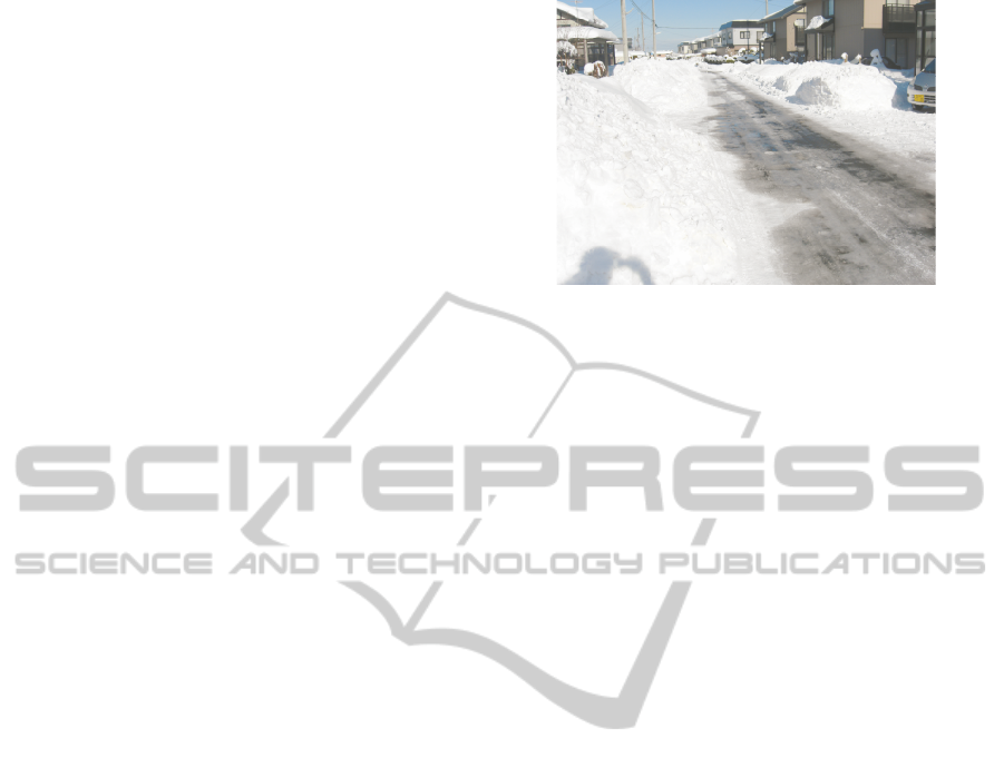
In the area where it snows heavily, snow removal of a road cannot often catch up with snowfall. Especially,
a community road becomes too narrow for vehicles to pass each other since snow removal is insufficient
compared with a main street. To obtain this information, this paper presents the novel method to measure the
distance between a vehicle and a snow wall of shoulder by a single camera. Our method creates the inverse
perspective mapping (IPM) image by projecting an input image to the virtual plane which is parallel to the
moving direction of the vehicle and which is perpendicular to the road surface. Then, the distance to the side
wall is calculated from the histogram whose bin is the length of an optical flow detected in the IPM image.
The optical flow of the IPM image is detected by a block matching and the motion of the side wall is obtained
from the peak of the histogram. The narrow way is detected by results measured by several vehicles with a
backup camera.Our method is robust to changes in the appearance of the texture on the side wall that occur
when a vehicle moves along a road.
1 INTRODUCTION
In the northern part of Japan, there are many areas
where it snows heavily. In these areas, snow removal
of a road is important for citizens’ life. If road width
is wide enough, vehicles can pass mutually even if
snow is stacked to the road shoulder. However, there
are many narrow community roads in the local city of
Japan. After snowfall, these roads become too nar-
row for vehicles to pass mutually as shown in Fig.1
and this situation causes a minor collision or traffic
congestion. Since it’s difficult to pass through a nar-
row road, vehicles are gathered in a wide main street.
This causes the further traffic congestion. If the road
information, such as narrowness of the road, is timely
given to drivers, this problem will be improved be-
cause drivers can choose the course for bypassing
these points. However, it’s not easy to know the cur-
rent situation of community roads because most of
them are not equipped with a traffic surveillance cam-
era.
We aim at realizing the system which detects the
place through which the road is too narrow for vehi-
cles to pass mutually owing to the snow stacked to
the shoulder. In order to estimate narrowness of the
road, this system uses the distance between the ve-
hicle and a snow side wall, measured by a lot of ve-
hicles with a backup camera. Since vehicles with a
backup camera for parking support increases recently
in Japan, our method acquires the distance informa-
tion from a backup camera. This system assumes that
the distance information measured by each vehicle is
sent to a base station by a cell phone line with posi-
tion information obtained from GPS. The road point
where many vehicles output short distance is judged
to be narrow. Since the distance information collected
by many vehicles is used for analysis, it does not be-
come a problem even if some vehicles fail to measure
the distance occasionally.
This paper describes the novel method how to
measure the distance between the vehicle and the side
wall by a single camera, especially a backup camera.
Since a backup camera uses a wide-angle lens, image
distortion is severe. Therefore, distance measurement
is difficult for the usual motion stereo. Our method
solves this problem by processing in the inverse per-
spective mapping (IPM) image. At first, the IPM im-
age is created by projecting an input image to the vir-
tual plane which is parallel to the moving direction
of the vehicle and which is perpendicular to the road
surface. Then, the distance to the side wall is calcu-
lated from the histogram whose bin is the length of an
optical flow detected in the IPM image. Our method
assumes that a vehicle goes straight along the road in
502
Onoguchi K. and Sato T..
Snow Side Wall Detection using a Single Camera.
DOI: 10.5220/0004759105020509
In Proceedings of the 3rd International Conference on Pattern Recognition Applications and Methods (ICPRAM-2014), pages 502-509
ISBN: 978-989-758-018-5
Copyright
c
2014 SCITEPRESS (Science and Technology Publications, Lda.)
a short time. The moving direction and the moving
distance are estimated from images of a backup cam-
era. The distance to the side wall is calculated only
while a vehicle goes straight. Since corresponding
between features is performed by a block matching
in the IPM image and the motion vector is estimated
from the peak of the histogram, our method is robust
to changes in the appearance of the texture on the side
wall that occurs when a vehicle moves along a road.
The remainder of this paper is organized as fol-
lows. In Sect.2, related works are reviewed briefly.
In Sect.3, the outline of the proposed method is de-
scribed. In Sect.4, the method to calculate the dis-
tance to the side wall is explained in detail. In Sect.5,
experimental results performed to simulation images
and several snow road scenes are discussed. Conclu-
sions are presented in Sect.6.
2 RELATED WORKS
Stereo vision is often used for measuring the dis-
tance to an object with cameras(Dhond and Aggar-
wal, 1989),(Hoff and Ahuja, 1989). Various meth-
ods which can acquire a dense depth map have been
proposed and used for automobile applications, such
as obstacle detection, road boundary detection and
so on(Einecke and Eggert, 2013),(Suhr and Jung,
2013),(M. Michael and Schlipsing, 2013),(C. Guo
and Naito, 2013),(M. Enzweiler and Franke, 2013).
A commercial car with the collision avoidance sys-
tem using a stereo camera has already been pro-
duced(Eyesight, 2013)(K. Saneyoshi and Sogawa,
1993)(Sogawa and Hanawa, 2002). Although stereo
vision is effective in distance measurement with a
camera, it requires higher cost than monocular vision
because it needs calibrated two cameras. Therefore,
there are few vehicles which have been equipped with
stereo cameras.
On the other hand, vehicles with a single camera
for rear view monitor or drive recorder are increas-
ing. Especially, vehicles with a backup camera for
parking support are rapidly increasing in Japan as the
car navigation system spreads widely. For this reason,
we proposes the method which measures the distance
to the snow side wall by a single camera, especially
a backup camera. Although a lot of methods have
been proposed for distance measurement with a sin-
gle camera, motion stereo is generally used in auto-
mobile applications(Huang, 1994)(A. Wedel and Cre-
mers, 2006)(A.J. Davison and Stasse, 2007). Motion
stereo needs to search corresponding points between
two frames taken at different points or it needs to track
feature points between frames. However, an image of
Figure 1: Snow wall of shoulder.
a backup camera has a severe distortion. In addition,
appearance of the texture on the side wall changes a
lot as the vehicle moves forward since the side wall
is parallel to the moving direction of the vehicle. In
addition, a lot of similar texture exist on the snow side
wall. Therefore, it’s difficult to estimate the distance
to the snow side wall stably by conventional methods.
3 OUTLINE OF THE PROPOSED
METHOD
Figure 2 shows the model of the driving environment
which the proposed method assumes. The distance
x between the on-vehicle camera and the side wall
along the road is calculated from the moving distance
of a vehicle and the movement of the side wall in the
IPM image when a vehicle moves forward. The pro-
posed method calculates the distance to the side wall
near a vehicle. Therefore, it is assumed that the side
wall consists of planes perpendicular to a road sur-
face.
Figure 3 shows the procedure of the proposed
method. At first, the motion of ego-vehicle is es-
timated from image sequences of a backup camera.
The motion vector is estimated from optical flows de-
tected on a road surface. Our method decides that
an ego-vehicle moves straight when the motion vec-
tor shows the upward direction in a certain period of
time. When a vehicle moves straight, the inverse per-
spective mapping (IPM) image is created and opti-
cal flows are detected in the IPM image by the block
matching. If the wall is close to a vehicle, the move-
ment of the wall in the IPM image is large as shown
in Fig. 4(a) and the magnitude of the optical flow is
also large. If the wall is far from a vehicle, the move-
ment of the wall in the IPM image is small as shown
in Fig. 4(b) and the magnitude of the optical flow is
also small. Then, a histogram whose bin is the mag-
nitude of the optical flow is created. The magnitude
SnowSideWallDetectionusingaSingleCamera
503
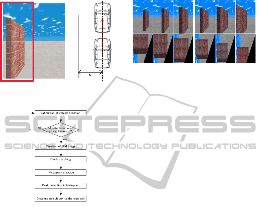
(a) Side wall (b) Relation between a
vehicle and a wall
Figure 2: Model of driving environment.
Figure 3: Outline of the proposed method.
with the maximum peak in this histogram is selected
as the movement of the side wall in the IPM image.
Finally, the distance between a vehicle and the side
wall is calculated from this movement and the motion
of an ego-vehicle.
4 ESTIMATION OF VEHICLE’S
MOTION
The motion of an ego-vehicle is estimated from the
optical flow detected on a road plane by the Lucas-
Kanade method(Lucas and Kanade, 2008). Figure
5(a) shows flow vectors detected in an image of a
backup camera. Extremely long flows are deleted as
incorrect ones. Since lens distortion is large in the
far area, the optical flow is detected only on the road
surface near the camera. An image is divided into
square blocks, as shown in 5(b) and an average flow
is calculated in each block. Then, a histogram of flow
(a) Near (b) Far
Figure 4: IPM image.
direction is created by voting the length of each av-
erage flow. A direction in a histogram is quantized
every 10 degrees. Figure 5(c) shows the example of
a histogram. In an image of a backup camera, let the
leftward direction be 0 degree, let the downward di-
rection be 90 degrees, let the rightward direction be
180 degree and let the upward direction be 270 de-
grees. When a vehicle moves straightforward, the
maximum peak of a histogram appears around 270
degrees because a backup camera takes a rear-view.
When the maximum peak of a histogram is observed
around 270 degrees in a certain period of time, our
method decides that an ego-vehicle moves straight-
forward. When an ego-vehicle moves straightfor-
ward, flow vectors in the camera coordinate system
whose direction are around 270 degrees are converted
to the vehicle coordinate system. Conversion param-
eters are determined in advance by the camera cali-
bration. We use a mat on which the square grid pat-
tern is drawn for calibration. This mat is set on the
ground in front of a backup camera. In both the cam-
era coordinate system and the vehicle coordinate sys-
tem, the position of the grid corner is manually mea-
sured and the table corresponding between these co-
ordinate systems is created. The conversion parame-
ter is calculated by solving the perspective projection
matrix using this table. The average length of con-
verted flow vectors is used as the moving distance of
an ego-vehicle.
5 CREATION OF IPM IMAGE
The inverse perspective mapping (IPM) usually con-
verts the coordinate system of the image plane to
the coordinate system of the road surface to create a
bird’s-eye view image which looks down a road from
the sky(Bertozzi and Broggi, 1997). Our method con-
verts an image to the virtual plane which is parallel to
the moving direction of the vehicle and perpendicular
to the road surface. This vertical plane is set between
ICPRAM2014-InternationalConferenceonPatternRecognitionApplicationsandMethods
504
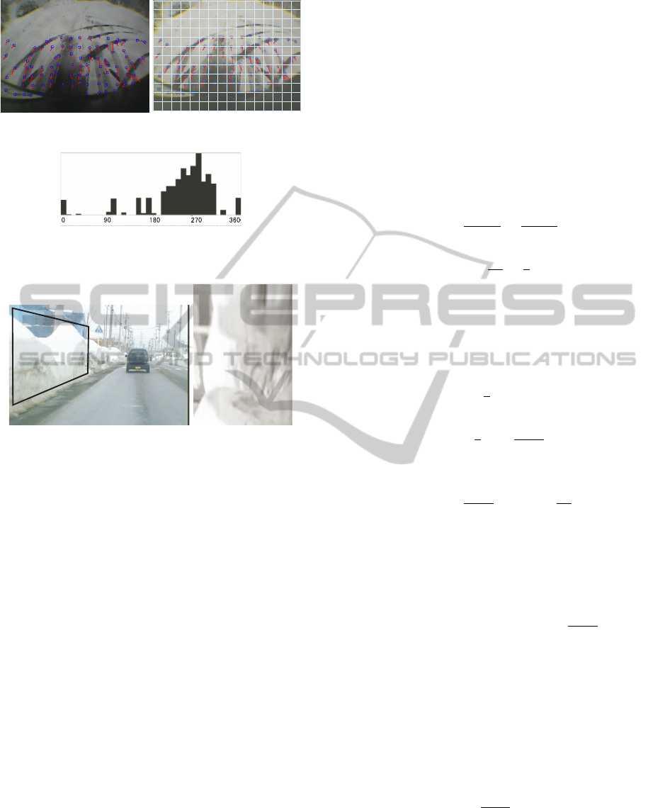
(a) Optical flow (b) Square blocks
(c) Histogram of flow direction
Figure 5: Optical flow from the backup camera.
(a) Input image (b) IPM image
mapped on the
virtual plane
Figure 6: Example of IPM image.
the side wall and an on-vehicle camera. The homog-
raphy matrix(Onoguchi, 1998) is used for projecting
an input image to the virtual plane. In the IPM im-
age, the region distant form a vehicle has low reso-
lution. However, this problem does not affect subse-
quent processing since the proposed method uses only
the region near a vehicle. Figure 6 shows the example
of the inverse perspective mapping. Figure 6(a) shows
an input image. The rectangular ROI is set in the left
side of an input image for creating the IPM image.
Figure 6(b) shows the IPM image created from the
image of the ROI. The position and the shape of the
ROI is fixed manually when a camera is installed.
6 DISTANCE CALCULATION TO
THE SIDE WALL
We explain the method which calculates the distance
between an on-vehicle camera and the side wall by
using Fig.7.
In Fig.7, a camera mounted on a vehicle moves
∆y from right to left. Let P
1
denote the focus of a
camera at the right position and let P
2
denote the focus
of a camera at the left position. At P
1
, the point k on
the side wall is projected to p
1
on the image plane
and at P
2
, k is projected to p
2
on the image plane.
The point k
1
(k
2
) is an intersection of the virtual plane
and the straight line connecting k and p
1
(p
2
). Let ∆x
denote the distance between the virtual plane and the
focus of a camera and x denote the distance between
the side wall and the focus of a camera. The angle
θ
1
(θ
2
) between the virtual plane and a straight line
connecting k and p
2
(p
1
) is given by
tan θ
1
=
∆x
b − ∆y
=
x
y − ∆y
(1)
tan θ
2
=
∆x
a
=
x
y
, (2)
where a is the distance on the virtual plane from
P
1
to k
1
and b is the distance on the virtual plane from
P
2
to k
2
.
The distance a and b on the virtual plane are given
by
a =
y
x
∆x. (3)
b = ∆y +
y
x
∆x −
∆x∆y
x
. (4)
Therefore, the difference b − a is given by
b − a = ∆y −
∆x∆y
x
= ∆y(1 −
∆x
x
). (5)
Figure 8 shows IPM images obtained by project-
ing the side wall to a virtual plane at the position P
1
and the position P
2
. The distance D between corre-
sponding points is given by
sD = a − (b − ∆y) = −(b − a) + ∆y =
∆x∆y
x
, (6)
where s is the constant magnification which
changes the distance on an IMP image into the dis-
tance on an virtual plane. In order to estimate s, we
put the calibration board on which the square grid pat-
tern is drawn on the position of the virtual plane. Let
B denote the size of the square grid and let B
IPM
de-
note the size of the square grid in the IPM image. s is
given by
s =
B
B
IPM
(7)
Because the moving the distance ∆y of a vehicle is
given by Sec. 4 and the distance ∆x between a camera
and the virtual plane is constant, the distance x to the
side wall is given by
SnowSideWallDetectionusingaSingleCamera
505
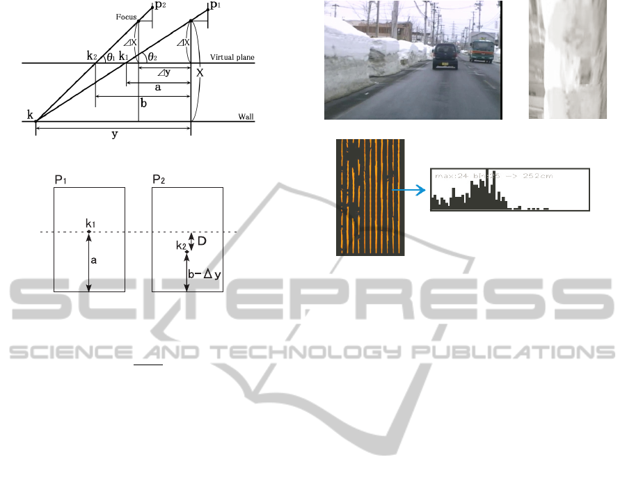
Figure 7: Inverse perspective projection to virtual plane.
Figure 8: IPM image at P
1
and P
2
.
x =
∆x∆y
sD
. (8)
7 CORRESPONDING BETWEEN
IPM IMAGES
The distance D between corresponding points are es-
timated by the block matching in IPM images created
at P
1
and P
2
. In the IPM image, the texture around
the corresponding point at P
1
is similar to the tex-
ture around it at P2 because the appearance of tex-
tures on the side wall is not subject to influence of
the perspective projection. Thus, our method uses the
cross-correlation for searching corresponding points
between IPM images.
Figure 9(b) shows the IPM image of Fig.9(a) and
Fig. 9(c) shows optical flows detected in Fig.9(b).
The optical flow is detected by the block matching.
Since the distance to the side wall is calculated only
when the vehicle moves straightforward, the direction
of the optical flow is almost vertical and the vertical
length is similar in the IPM image. Therefore, the
histogram whose bin is the vertical length of the flow
vector is created to estimate the distance D, as shown
in Fig.9(c). The vertical length of the bin with the
maximum peak is selected as the distance D. The ver-
tical length in the IPM image can be converted to the
actual distance D on the virtual plane because the dis-
tance ∆x between the camera and the virtual plane is
constant. The conversion parameter is beforehand es-
timated by the calibration.
(a) Input image (b) IPM image
(c) Histogram estimated in the IPM image
Figure 9: Movement of the side wall in the IPM image.
8 EXPERIMENTS
We conducted experiments which estimated the dis-
tance to the side wall in simulation scenes and real
road scenes. An image size is 320× 240 pixels and the
processing time is 30 f ps on PC with Xeon 2.67GHz
CPU.
8.1 Experiments on Simulation Scenes
The accuracy of the distance to the side wall is evalu-
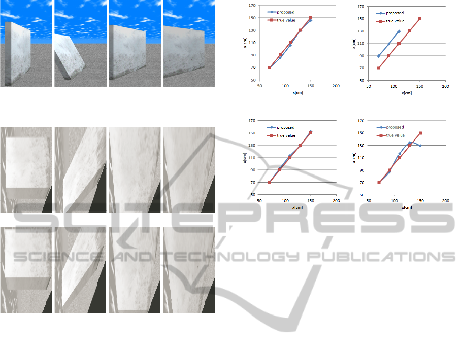
ated by using simulation images. Figure 10 shows im-
ages of snow side walls created by CG software. The
side wall in Fig.10 (a) is parallel to the moving direc-
tion of a vehicle and perpendicular to the road surface.
The side wall in Fig.10 (b) is parallel to the moving
direction of a vehicle but slant to the road surface.
The side walls in Fig.10 (c) and (d) are not parallel to
the moving direction of a vehicle. In Fig.10 (c), the
angle between the side wall and the moving direction
is 15 degree. In Fig.10 (d), the angle between the side
wall and the moving direction is 30 degrees. Figure
11 shows the IPM image obtained from Fig.10. The
distance to the snow side wall is estimated from the
movement between the upper image and the lower im-
age. Figure 12 shows estimation results when the dis-
tance to the side wall is 70cm, 90cm, 110cm, 130cm or
150cm. Figure 12 (a) shows that the proposed method
can estimate the distance to the side wall correctly be-
cause a measurement value is almost equal to a true
value. In Fig.12(b), a true value shows the the dis-
tance to the ground position of the side wall. Since
the side wall leans outside, a measurement value is
ICPRAM2014-InternationalConferenceonPatternRecognitionApplicationsandMethods
506
(a) (b) (c) (d)
Figure 10: The result of a simulation scene (Input image).
(a) (b) (c) (d)
(e) (f) (g) (h)
Figure 11: The result of a simulation scene (IPM image).
slightly larger than the true value. In Fig.12(b), the
measurement value of 130cm and 150cm is missing
because most of the side wall is out of the IPM im-
age. Fig.12 (c) shows the result similar to Fig.12 (a).
This result shows the proposed method can estimate
the distance to the side wall even if the moving direc-
tion of a vehicle is shifted about 15 degree with the
side wall.
8.2 Experiments on Real Road Scenes
Experiments were conducted using images taken at a
snowy road by a backup camera and a front camera.
Figures 13 - 18 show results of the backup camera.
In these figures, the upper image shows the input im-
age and the lower left image shows the IPM image.
The lower right graph shows the distance to the snow
side wall. In this graph, a horizontal axis shows time
(the number of frames) and a vertical axis shows the
distance between a vehicle and the side wall. The
origin is the upper left. The upper horizontal grey
line shows 100cm distance and the lower horizontal
grey line shows 200cm distance. Input images were
captured by the same backup camera. Therefore, the
(a) (b)
(c) (d)
Figure 12: The result of a simulation scene (Accuracy of
distance).
shape and the position of a rectangular region for cre-
ating the IPM image were same in Figs.13 - 18. Be-
cause in these scene, the ego-vehicle almost moves
straight along a snow wall at a fixed speed, we es-
timated the distance to the snow side wall from the
cross line between a road and a snow wall, which was
manually extracted in each scene. The relation be-
tween the distance and the lower endpoint of the cross
line was beforehand obtained by the calibration that
was performed in advance.
The snow side walls of Figs.13, 14, 15, 16, 17
and 18 are away from a backup camera about 140cm,
180cm, 180cm, 180cm, 130cm and 130cm respec-
tively. In the lower right graphs of Figs.13 - 18, most
of the measurements show the values near these esti-
mates. These results show that the proposed method
can measure the distance to the side wall stably from
the low resolution image captured by a backup cam-
era.
Since we aim at realizing the system which deter-
mines the road situation by the distance information
collected by a lot of vehicles with a backup camera,
some error which occurred by the individual vehicle
is not a problem. Because the average of measure-
ment error is important, we evaluated it in two scenes
where the ego vehicle moves straight along a snow
wall, while keeping the distance to a snow wall at
100cm and 150cm. As a result of evaluation using the
image of 1, 000 frames, the measurement error was
−1.8cm in 100cm and it was 10.2cm in 150cm. This
result shows that the proposed method is effective in
the system which we are going to realize although the
SnowSideWallDetectionusingaSingleCamera
507
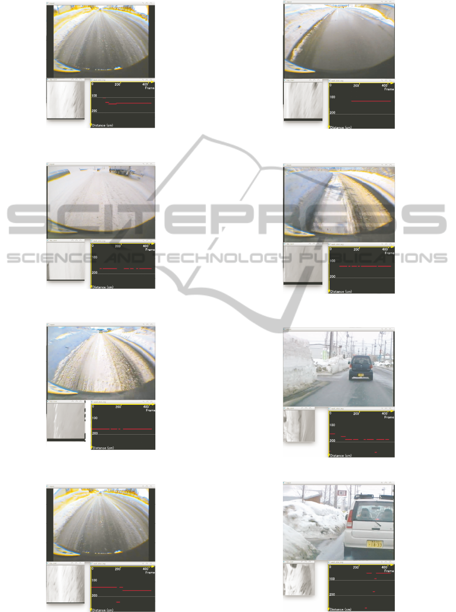
Figure 13: The result of a real road scene 1(Backup cam-
era).
Figure 14: The result of a real road scene 2(Backup cam-
era).
Figure 15: The result of a real road scene 3(Backup cam-
era).
Figure 16: The result of a real road scene 4(Backup cam-
era).
Figure 17: The result of a real road scene 5(Backup cam-
era).
Figure 18: The result of a real road scene 6(Backup cam-
era).
Figure 19: The result of a real road scene 1 (Front camera).
Figure 20: The result of a real road scene 2 (Front camera).
ICPRAM2014-InternationalConferenceonPatternRecognitionApplicationsandMethods
508

accuracy is not better than the conventional method
using a standard lens or a range sensor.
Figures 19 and 20 show results of the front cam-
era. The snow side walls in Figs. 19 and 20 are away
from a front camera about 180cm and 50cm. A vehi-
cle kept the almost same distance from the side wall.
In the lower right graphs of Figs. 19 and 20, most
of measurements are plotted around correct values.
Since the focal length of the front camera is longer
than that of the backup camera, the side wall in the
IPM image of the front camera is clearer than that of
the backup camera. Thus, the distance to the snow
side wall can be estimated more accurately.
9 CONCLUSIONS
This paper presented the method which can measure
the distance between a vehicle and the snow wall of
shoulder by a single camera, especially a backup cam-
era. Our method corresponds features in the IPM im-
age and estimates the motion vector from the peak of
the histogram whose bin is the magnitude of the opti-
cal flow. Therefore, it is robust to the change in the ap-
pearance of the feature on the side wall, which occurs
when a vehicle moves along a road. Experimental re-
sults using simulation scenes and snow road scenes
show the effectiveness of the proposed method.
In the future, we will evaluate the accuracy of the
distance in real road scenes by comparing with the
measured value of a laser sensor and develop the sys-
tem which estimate passing difficulty points by inte-
grating the distance information obtained from a lot
of vehicles with GPS data. It is also a future work to
measure the influence of the error included in moving
distance ∆y.
REFERENCES
A. Wedel, U. Franke, J. K. T. B. and Cremers, D. (2006).
Realtime depth estimation and obstacle detection from
monocular video. Pattern Recognition, Lecture Notes
in Computer Science, 4174:475–484.
A.J. Davison, I.D. Reid, N. D. M. and Stasse, O. (2007).
Monoslm: Real-time single camera slam. IEEE Trans.
on PAMI, 29(6):1052–1067.
Bertozzi, M. and Broggi, A. (1997). Vision-based vehicle
guidance. Computer, 30(7):49–55.
C. Guo, J. Meguro, Y. K. and Naito, T. (2013). Cadas: a
multimodal advanced driver assistance system for nor-
mal urban streets based on road context understand-
ing. Proceedings of IV2013, pages 228–235.
Dhond, U. R. and Aggarwal, J. K. (1989). Structure from
stereo - a review. IEEE Trans. on Systems, Man and
Cybernetics,, 19(6):1489–1510.
Einecke, N. and Eggert, J. (2013). Stereo image warping
for improved depth estimation of road surfaces. Pro-
ceedings of IV2013, pages 189–194.
Eyesight (2013). http://www.subaru.com/engineering/
safety.html.
Hoff, W. and Ahuja, N. (1989). Surfaces from stereo: In-
tegrating feature matching, disparity estimation, and
contour detection. IEEE Trans. on PAMI,, 11(2):121–
136.
Huang, T. S. (1994). Motion and structure from feature
correspondences: a review. Proceedings of the IEEE,
82(2):252–268.
K. Saneyoshi, K. Hanawa, K. K. and Sogawa, Y. (1993).
3-d image recognition system for drive assist. Pro-
ceedings of IV’93, pages 60–65.
Lucas, B. D. and Kanade, T. (2008). An iterative image
registration technique with an application to stereo vi-
sioin. Proceedings of Image Understanding Work-
shop, pages 121–130.
M. Enzweiler, P. Greiner, C. K. and Franke, U. (2013). To-
wards multi-cue urban curb recognition. Proceedings
of IV2013, pages 902–907.
M. Michael, J. Salmen, J. S. and Schlipsing, M. (2013).
Real-time stereo vision: Optimizing semi-global
matching. Proceedings of IV2013, pages 1197–1202.
Onoguchi, K. (1998). Shadow elimination method for mov-
ing object detection. Proceedings of ICPR’98, pages
583–587.
Sogawa, Y. and Hanawa, K. (2002). Sensors for automo-
biles. forward direction recognition system with stereo
vision for automobiles. Journal of the Society of Au-
tomotive Engineers of Japan (Japanese, 56(4):34–39.
Suhr, J. K. and Jung, H. G. (2013). Noise resilient road
surface and free space estimation using dense stereo.
Proceedings of IV2013, pages 461–466.
SnowSideWallDetectionusingaSingleCamera
509
