
iArch - An IDE for Supporting Abstraction-aware Design Traceability
Di Ai, Naoyasu Ubayashi, Peiyuan Li, Shintaro Hosoai and Yasutaka Kamei
Kyushu University, Fukuoka, Japan
Keywords:
Architecture, Interface, Abstraction, Traceability, Type System, Model-Driven Development.
Abstract:
Abstraction has been an important issue in software engineering. However, it is not easy to design an architec-
ture reflecting the intention of developers and implement the result of a design as a program while preserving
an adequate abstraction level. To deal with this problem, we provide iArch, an IDE (Integrated Development
Environment) for supporting abstraction-aware traceability between design and code. The iArch IDE is based
on Archface, an architectural interface mechanism exposing a set of architectural points that should be shared
between design and code. An abstraction level is determined by selecting architectural points.
1 INTRODUCTION
Abstraction has been an important issue in software
engineering research (Kramer, 2007). MDD (Model-
Driven Development) is a promising approach to
deal with abstraction. An application can be de-
veloped at a high abstraction level by using a DSL
(Domain-Specific Language) or a DSML (Domain-
Specific Modeling Language). We do not need pro-
gram code, because it can be fully generated from its
design model if necessary. However, programming
has not yet disappeared from most software develop-
ment projects, because the approach of DSLs can be
only applied to mature application domains. In or-
dinary development, both design activities and pro-
gramming have their own roles. Although separation
of design and implementation concerns is important,
it is not easy to design an architecture reflecting the
intention of developers and implement the result of
a design as a program while preserving architectural
correctness and an adequate abstraction level.
To deal with this problem, we previously proposed
an approach that treats a design model as a first-class
software module (Ubayashi and Kamei, 2013). A de-
sign model such as a UML diagram is regarded as
a design module. To realize design modules, we in-
troduced Archface (Ubayashi et al., 2010), an archi-
tectural interface mechanism. Archface exposes a set
of architectural points that should be shared between
design and code. Archface plays a role as a design
interface for a design module and as a program in-
terface for a program module. As a well-modular
program can be obtained by defining deeply consid-
ered program interfaces between program modules,
an excellent separation of concerns among design and
program modules can be captured by defining well-
balanced Archface. The traceability between design
and code can be automatically maintained by the type
system of Archface. Design and code are synchro-
nized when both a design model and its code conform
to the same Archface. Abstraction is taken into ac-
count in this synchronization, because an abstraction
level is determined by selecting shared architectural
points declared in Archface.
This paper provides iArch, an IDE (Integrated De-
velopment Environment) for supporting abstraction-
aware traceability between design and code. The
iArch IDE consists of the followings: 1) model &
program editor, 2) Archface generator, 3) abstraction-
aware compiler, 4) abstraction metrics calculation,
and 5) refactoring support. The contribution of this
paper is to show how to realize an Archface-Centric
MDD tool based on a new type system that can be ap-
plied to not only a program but also a design model.
This paper is structured as follows. Archface-
Centric MDD is introduced in Section 2. The imple-
mentation of iArch is illustrated in Section 3. Discus-
sion and future work are provided in Section 4.
2 ARCHFACE-CENTRIC MDD
In this section, we provide a background on Archface-
Centric MDD, a foundation of iArch, by excerpting
from our preliminary work (Ubayashi and Kamei,
2013).
442
Ai D., Ubayashi N., Li P., Hosoai S. and Kamei Y..
iArch - An IDE for Supporting Abstraction-aware Design Traceability.
DOI: 10.5220/0004762604420447
In Proceedings of the 2nd International Conference on Model-Driven Engineering and Software Development (MODELSWARD-2014), pages 442-447
ISBN: 978-989-758-007-9
Copyright
c
2014 SCITEPRESS (Science and Technology Publications, Lda.)
㻰㼑㼟㼕㼓㼚㻌㻹㼛㼐㼡㼘㼑
㻼㼞㼛㼓㼞㼍㼙㻌㻹㼛㼐㼡㼘㼑
㼜㼡㼎㼘㼕㼏㻌㼏㼘㼍㼟㼟㻌㻭䚷㼧
䚷㻌㼜㼡㼎㼘㼕㼏㻌㼢㼛㼕㼐㻌㼙㼍㻌㻔㻕㻌㼧
㻌㻌㻌㻌㼩
㻌㻌㻌㻌䈈
㻌㼩
㼜㼡㼎㼘㼕㼏㻌㼏㼘㼍㼟㼟㻌㻮㻌㼧
㻌㻌䈈
㼩
㻼㼞㼛㼓㼞㼍㼙㻌㻼㼛㼕㼚㼠㼟
㻰㼑㼟㼕㼓㼚㻌㻼㼛㼕㼚㼠㼟
㻰㼑㼟㼕㼓㼚㻌㻹㼛㼐㼡㼘㼑
㻼㼞㼛㼓㼞㼍㼙㻌㻹㼛㼐㼡㼘㼑
㼜㼡㼎㼘㼕㼏㻌㼏㼘㼍㼟㼟㻌㼄㻌㼧
䚷㻌㼜㼡㼎㼘㼕㼏㻌㼢㼛㼕㼐㻌㼙㼤㻌㻔㻕㼧
㻌㻌㻌㻌
㻌㻌㻌㻌㼩
㻌㻌㻌㻌䈈
㻌㼩
㼜㼡㼎㼘㼕㼏㻌㼏㼘㼍㼟㼟㻌㼅㻌㼧
㻌㻌䈈
㼩
㻼㼞㼛㼓㼞㼍㼙㻌㻼㼛㼕㼚㼠㼟
㻰㼑㼟㼕㼓㼚㻌㻼㼛㼕㼚㼠㼟
㻭㼞㼏㼔㼒㼍㼏㼑
㻭㼞㼏㼔㼜㼛㼕㼚㼠㼟
㻹㼛㼐㼑㼘㼑㼐
㻮㼥
㻰㼑㼟㼕㼓㼚㻌㻼㼛㼕㼚㼠㼟
㻵㼙㼜㼘㼑㼙㼑㼚㼠㼑㼐
㻮㼥
㻼㼞㼛㼓㼞㼍㼙㻌㼜㼛㼕㼚㼠㼟
㼀㼞㼍㼏㼑㼍㼎㼕㼘㼕㼠㼥
㻯㼛㼚㼟㼕㼟㼠㼑㼚㼏㼥
㻮㼑㼠㼣㼑㼑㼚
㻯㼍㼘㼘㼑㼞㻛㻯㼍㼘㼘㼑㼑
㻯㼛㼚㼟㼕㼟㼠㼑㼚㼏㼥
㻮㼑㼠㼣㼑㼑㼚
㻹㼛㼐㼑㼘㻌㼂㼕㼑㼣㼟
Figure 1: Archface: Design+Program Interface.
Table 1: Design/Program Points and Archpoints.
Diagram Design point Program point Archpoint (Pointcut)
(UML2 metamodel) (Java)
Class diagram
Class
class a class (
class
)
(UML)
Operation
method a method (
method
)
Property
field a field (
field
)
Sequence diagram
Message
method call a mcall (
call
)*
(UML)
-sendEvent:MessageEnd
Message
method exec a mexec (
execution
)*
-receiveEvent:MessageEnd
Interaction
(control flow) (
cflow
)* **
Data flow (
Property
def) field set a def (
set
)*
(
Property
use) field get a use (
get
)*
*) AspectJ pointcut
**) Used with
call
or
execution
pointcut
2.1 Basic Concept
Figure 1 shows the relation among design modules,
program modules, and Archface, an interface for
bridging them. The same Archface is modeled by a
design model and is implemented by program code.
If each type check is correct, a design model is trace-
able to the code. Archface plays a role of design inter-
face for a design model. At the same time, Archface
plays a role of program interface for code. A design
specification consists of multiple design modules in
which each module represents an individual design
concern. Design modules support MDSOC (Multi-
Dimensional Separation Of Concerns) (Tarr et al.,
1999). Archface exposes architectural points shared
between design and code. These points termed arch-
points have to be modeled as design points in a UML
model and have to be implemented as program points
in its code. Class declarations, methods, and events
such as message send are called design points.
Table 1 shows design/program points and arch-
points. These points can be mapped each other. The
idea of archpoints and their selection originates in
AOP (Aspect-Oriented Programming) notion such as
join points and pointcuts. Archpoints correspond to
join points in AspectJ (Kiczales et al., 2001). We fo-
cus on archpoints embedded in class and sequence di-
agrams, because structural and behavioral aspects of
㻜㻝㻦㻌㼕㼚㼠㼑㼞㼒㼍㼏㼑㻌㼏㼛㼙㼜㼛㼚㼑㼚㼠㻌㼏㻿㼡㼎㼖㼑㼏㼠㻌㼧
㻜㻞㻦㻌㻌㻌㼜㼛㼞㼠㻌㼍㼐㼐㻻㼎㼟㼑㼞㼢㼑㼞㻔㻕㻦
㻜㻟㻦㻌㻌㻌㻌㻌㻌㻌㻌㼑㼤㼑㼏㼡㼠㼕㼛㼚㻔㼢㼛㼕㼐㻌㼍㼐㼐㻻㼎㼟㼑㼞㼢㼑㼞㻔㻻㼎㼟㼑㼞㼢㼑㼞㻌㼛㻕㻕㻧
㻜㻠㻦㻌㻌㻌㼜㼛㼞㼠㻌㼞㼑㼙㼛㼢㼑㻻㼎㼟㼑㼞㼢㼑㼞㻔㻕㻦
㻜㻡㻦㻌㻌㻌㻌㻌㻌㻌㻌㼑㼤㼑㼏㼡㼠㼕㼛㼚㻔㼢㼛㼕㼐㻌㼞㼑㼙㼛㼢㼑㻻㼎㼟㼑㼞㼢㼑㼞㻔㻻㼎㼟㼑㼞㼢㼑㼞㻌㼛㻕㻕㻧
㻜㻢㻦㻌㻌㻌㼜㼛㼞㼠㻌㼓㼑㼠㻿㼠㼍㼠㼑㻔㻕㻦
㻜㻣㻦㻌㻌㻌㻌㻌㻌㻌㻌㼑㼤㼑㼏㼡㼠㼕㼛㼚㻔㻿㼠㼞㼕㼚㼓㻌㼓㼑㼠㻿㼠㼍㼠㼑㻔㻕㻕㻧
㻜㻤㻦㻌㻌㻌㼜㼛㼞㼠㻌㼟㼑㼠㻿㼠㼍㼠㼑㻔㻕㻦
㻜㻥㻦㻌㻌㻌㻌㻌㻌㻌㻌㼑㼤㼑㼏㼡㼠㼕㼛㼚㻔㼢㼛㼕㼐㻌㼟㼑㼠㻿㼠㼍㼠㼑㻔㻿㼠㼞㼕㼚㼓㻕㻕㻧
㻝㻜㻦㻌㼩
㻝㻝㻦
㻝㻞㻦㻌㼕㼚㼠㼑㼞㼒㼍㼏㼑㻌㼏㼛㼙㼜㼛㼚㼑㼚㼠㻌㼏㻿㼡㼎㼖㼑㼏㼠㻮㼑㼔㼍㼢㼕㼛㼞㻌㼑㼤㼠㼑㼚㼐㼟㻌㼏㻿㼡㼎㼖㼑㼏㼠㻌㼧
㻝㻟㻦㻌㻌㻌㼜㼛㼞㼠㻌㼚㼛㼠㼕㼒㼥㻻㼎㼟㼑㼞㼢㼑㼞㼟㻔㻕㻦
㻝㻠㻦㻌㻌㻌㻌㻌㻌㻌㻌㼏㼒㼘㼛㼣㻔㼟㼑㼠㻿㼠㼍㼠㼑㻔㻕㻕㻌㻒㻒㻌㼏㼍㼘㼘㻔㼡㼜㼐㼍㼠㼑㻔㻕㻕㻧
㻝㻡㻦㻌㼩
㻭㼞㼏㼔㼒㼍㼏㼑
㻰㼑㼟㼕㼓㼚㻌㻼㼛㼕㼚㼠
㻭㼞㼏㼔㼜㼛㼕㼚㼠
㻯㼛㼚㼟㼠㼞㼍㼕㼚㼠㻌㼍㼙㼛㼚㼓㻌
㼐㼑㼟㼕㼓㼚㻌㼜㼛㼕㼚㼠㼟
㻔㼙㼑㼟㼟㼍㼓㼑㻌㼟㼑㼝㼡㼑㼚㼏㼑㻕
㻜㻝㻦㻌㼜㼡㼎㼘㼕㼏㻌㼏㼘㼍㼟㼟㻌㻿㼡㼎㼖㼑㼏㼠㻌㼧
㻜㻞㻦㻌㻌㻌㼜㼞㼕㼢㼍㼠㼑㻌㼂㼑㼏㼠㼛㼞㻌㼛㼎㼟㼑㼞㼢㼑㼞㼟㻌㻩㻌㼚㼑㼣㻌㼂㼑㼏㼠㼛㼞㻔㻕㻧
㻜㻟㻦㻌㻌㻌㼜㼞㼕㼢㼍㼠㼑㻌㻿㼠㼞㼕㼚㼓㻌㼟㼠㼍㼠㼑㻌㻩㻌㻎㻎㻧
㻜㻠㻦㻌㻌㻌㼜㼡㼎㼘㼕㼏㻌㼢㼛㼕㼐㻌㼍㼐㼐㻻㼎㼟㼑㼞㼢㼑㼞㻔㻻㼎㼟㼑㼞㼢㼑㼞㻌㼛㻕㼧
㻜㻡㻦㻌㻌㻌㻌㻌㼛㼎㼟㼑㼞㼢㼑㼞㼟㻚㼍㼐㼐㻔㼛㻕㻧
㻜㻢㻦㻌㻌㻌㼩
㻜㻣㻦㻌㻌㻌㼜㼡㼎㼘㼕㼏㻌㼢㼛㼕㼐㻌㼞㼑㼙㼛㼢㼑㻻㼎㼟㼑㼞㼢㼑㼞㻔㻻㼎㼟㼑㼞㼢㼑㼞㻌㼛㻕㼧
㻜㻤㻦㻌㻌㻌㻌㻌㼛㼎㼟㼑㼞㼢㼑㼞㼟㻚㼞㼑㼙㼛㼢㼑㻔㼛㻕㻧
㻜㻥㻦㻌㻌㻌㼩
㻝㻜㻦㻌㻌㻌㼜㼡㼎㼘㼕㼏㻌㻿㼠㼞㼕㼚㼓㻌㼓㼑㼠㻿㼠㼍㼠㼑㻔㻕㻌㼧㻌㼞㼑㼠㼡㼞㼚㻌㼟㼠㼍㼠㼑㻧㻌㼩
㻝㻝㻦㻌㻌㻌㼜㼡㼎㼘㼕㼏㻌㼢㼛㼕㼐㻌㼟㼑㼠㻿㼠㼍㼠㼑㻔㻿㼠㼞㼕㼚㼓㻌㼟㻕㻌㼧
㻝㻞㻦㻌㻌㻌㻌㻌㼟㼠㼍㼠㼑㻌㻩㻌㼟㻧
㻝㻟㻦㻌㻌㻌㻌㻌㼒㼛㼞㻌㻔㼕㼚㼠㻌㼕㻌㻩㻌㻜㻧㻌㼕㻌㻨㻌㼛㼎㼟㼑㼞㼢㼑㼞㼟㻚㼟㼕㼦㼑㻔㻕㻧㻌㼕㻗㻗㻕
㻝㻠㻦㻌㻌㻌㻌㻌㻌㻌㻔㻔㻻㼎㼟㼑㼞㼢㼑㼞㻕㼛㼎㼟㼑㼞㼢㼑㼞㼟㻚㼓㼑㼠㻔㼕㻕㻕㻚㼡㼜㼐㼍㼠㼑㻔㻕㻧
㻝㻡㻦㻌㻌㻌㼩
㻝㻢㻦㻌㼩
㻼㼞㼛㼓㼞㼍㼙㻌㻹㼛㼐㼡㼘㼑㻌㻔㻶㼍㼢㼍㻌㻯㼘㼍㼟㼟㻕
㻼㼞㼛㼓㼞㼍㼙㻌
㻼㼛㼕㼚㼠
㻯㼛㼚㼟㼠㼞㼍㼕㼚㼠㻌㼍㼙㼛㼚㼓㻌
㼜㼞㼛㼓㼞㼍㼙㻌㼜㼛㼕㼚㼠㼟
㻔㼏㼍㼘㼘㼕㼚㼓㻌㼟㼑㼝㼡㼑㼚㼏㼑㻕
㻻㼎㼟㼑㼞㼢㼑㼞㻼㼍㼠㼠㼑㼞㼚㻯㻰
㻻㼎㼟㼑㼞㼢㼑㼞㻼㼍㼠㼠㼑㼞㼚㻿㻰
㻰㼑㼟㼕㼓㼚㻌㻹㼛㼐㼡㼘㼑㻌㻔㼁㻹㻸㻌㻰㼕㼍㼓㼞㼍㼙㻕
㼀㼥㼜㼑
㻯㼔㼑㼏㼗
㻿㻹㼀㻌㻿㼛㼘㼢㼑㼞
㼀㼥㼜㼑
㻯㼔㼑㼏㼗
㻿㻹㼀㻌㻿㼛㼘㼢㼑㼞
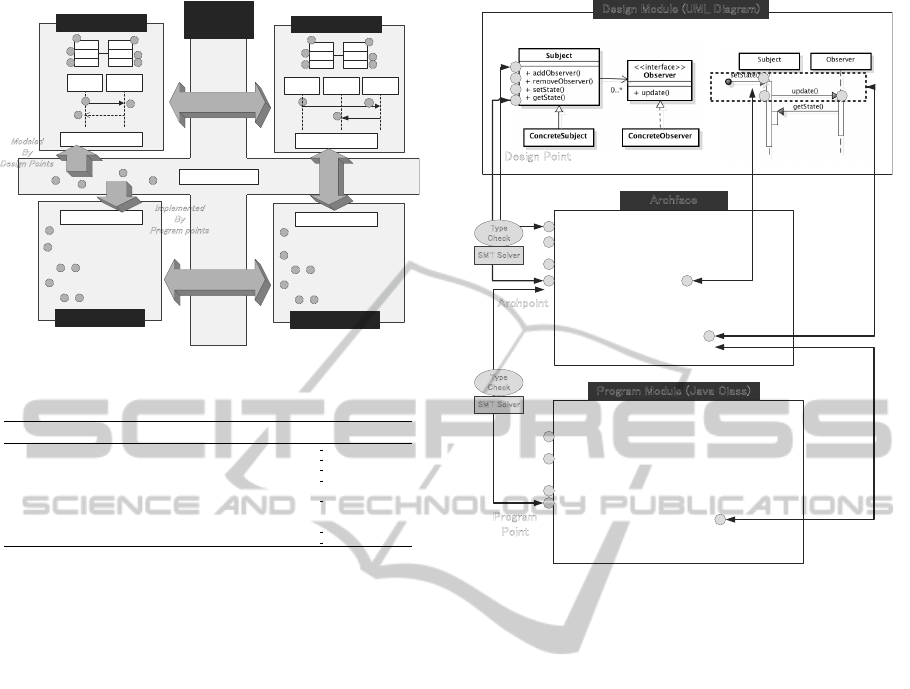
Figure 2: Archface-Centric MDD.
software architecture (Bass et al., 2003) can be basi-
cally represented using these diagrams. Archface con-
ceptually includes the notion of traditional program
interface, because a method definition can be inter-
preted as a provision of an archpoint selected by an
execution
pointcut.
2.2 Archface, Design and Code
We illustrate design and program modules using the
Observer pattern as an example. The Observer pat-
tern consists of a subject and observers. When the
state of a subject is changed, the subject notifies all
observers of this new state. Figure 2 shows the rela-
tion between these modules and Archface.
2.2.1 Archface
Archface, which supports component-and-connector
architecture (Allen and Garlan, 1994), consists of
two kinds of interface, component and connector.
The former exposes archpoints and the latter defines
how to coordinate archpoints. Hierarchical definitions
are possible, because both interfaces support inheri-
tance. A collaborative architecture can be encapsu-
lated into a group of component and connector inter-
faces. Pointcut & advice in AspectJ is used as a mech-
iArch-AnIDEforSupportingAbstraction-awareDesignTraceability
443

anism for exposing archpoints (pointcut) and coordi-
nating them (advice).
List 1 is a component interface for a subject.
Archface exposes archpoints from ports. Four port
declarations (line 02-07) correspond to the tradi-
tional interface in which each method declaration
can be regarded as exposure of
method execution
.
The
notifyObservers
port (line 11-12) exposes an
update call
archpoint that has to be called under
the control flow of
setState
. The operator &&
is used to symbolize Logical AND. This archpoint
is combined with an
update execution
archpoint
specified in a component interface for observers (List
2, line 02).
[List 1]
01: interface component cSubject {
02: port addObserver():
03: execution(void addObserver(Observer o));
04: port removeObserver():
05: execution(void removeObserver(Observer o));
06: port getState(): execution(String getState());
07: port setState(): execution(void setState(String));
08: }
09:
10: interface component cSubjectBehavior extends cSubject {
11: port notifyObservers():
12: cflow(setState()) && call(update());
13: }
[List 2]
01: interface component cObserver {
02: port update(): execution(void update());
03: }
04:
05: interface component cObserverBehavior extends cObserver {
06: port updateState():
07: cflow(update()) && call(String getState());
08: }
List 3 is a connector interface specifying the
coordination among archpoints exposed from com-
ponent’s ports. The execution of archpoints ex-
posed from component interfaces is coordinated by
connects
(
multiple
indicates the connection is re-
peatable). In
notifyChange
, an
update call
arch-
point in
cSubject
is bound to an
update execution
archpoint in
cObserver
.
[List 3]
01: inteface connector cObserverPattern(cSubject, cObserver);
02: inteface connector cObserverPatternBehavior
03: extends cObserverPattern {
04: connects multiple notifyChange
05: (cSubject.notifyObservers, cObserver.update);
06: connects obtainNewState
07: (cObserver.updateState, cSubject.getState);
08: }
09: }
2.2.2 Design and Program Modules
Both design and program modules are the same as tra-
ditional UML diagrams and code. However, there
is a crucial difference. An interface, Archface, re-
sides between them and it makes them software mod-
ules.
ObserverPatternCD
, a class diagram, and
ObserverPatternSD
, a sequence diagram shown in
Figure 2 are design modules faithful to the Archface
declared in List 1, 2, and 3. A program module is
also the same as a traditional module such as a Java
class. List 4 and 5 are Java classes implementing the
Archface.
[List 4]
01: public class Subject {
02: private Vector observers = new Vector();
03: private String state = "";
04: public void addObserver(Observer o) {
05: observers.add(o);
06: }
07: public void removeObserver(Observer o) {
08: observers.remove(o);
09: }
10: public String getState() {return state;}
11: public void setState(String s) {
12: state = s;
13: for (int i=0; i<observers.size(); i++)
14: ((Observer)observers.get(i)).update();
15: }
16: }
[List 5]
01: public class Observer {
02: private subject = new Subject();
03: private String state = "";
04: public void update() {
05: state = subject.getState();
06: System.out.println("Update received from Subject,
07: state changed to : " + state);
08: }
09: }
2.3 Abstraction-aware Traceability
To integrate design and program modules, each de-
sign module models its Archface and each program
module implements the same Archface. The confor-
mance to Archface can be checked by a type sys-
tem that takes into account not only program but
also design interfaces. The type checking is per-
formed by verifying whether or not a design point
(program point) corresponding to an archpoint exists
in a design module (program module) while satisfy-
ing constraints among design points (program points)
(e.g., the order of message sequences specified by
cflow
). Although traditional types are structural—
sets of method signatures, Archface is based on arch-
points including behavior—specified by the order of
archpoints because a design model imposes structural
or behavioral architectural constraints on a program.
There is a bisimulation relation between a design
and its code in terms of archpoints. The abstraction
structure modeled in a design is preserved in its code.
We can ignore program points that are not related
to archpoints when we check the design traceability.
Bisimulation is an important concept in the research
field of process algebra (Milner, 1989). Two process
are bisimilar if each process cannot be distinguished
from the other. A sequence of archpoints can be re-
garded as a process if we regard the sequence as an
LTS (Labeled Transition System). We cannot distin-
guish code from its associated design in terms of arch-
points. The novel point of our approach is the realiza-
tion of bisimulation in terms of a type system based
on Archface.
MODELSWARD2014-InternationalConferenceonModel-DrivenEngineeringandSoftwareDevelopment
444
㻯㼛㼙㼜㼕㼘㼑㻌㻱㼞㼞㼛㼞㻍
㼀㼔㼕㼟㻌㼐㼑㼟㼕㼓㼚㻌㼐㼛㼑㼟㻌㼚㼛㼠㻌
㼏㼛㼚㼒㼛㼞㼙㻌㼠㼛㻌
㻭㼞㼏㼔㼒㼍㼏㼑
㻚
㻭㼞㼏㼔㼒㼍㼏㼑
㻚
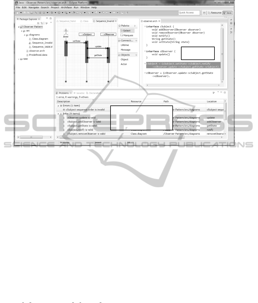
Figure 3: iArch IDE.
3 iArch
3.1 Tool Overview
The iArch IDE consists of the followings: 1) model &
program editor, 2) Archface generator, 3) abstraction-
aware compiler, 4) abstraction metrics calculation,
and 5) refactoring support. Using the model edi-
tor, we can make a design model and generate initial
Archface descriptions. The abstraction-aware com-
piler checks whether or not an Archface is modeled by
a design model and is implemented by the code. If the
code does not exist, the compiler generates the code
conforming to the design. The compiler supports the
preservation of consistency between design and code
in terms of an abstraction level specified by Archface.
However, it is an open question to explore an appre-
ciate abstraction structure and decide which abstrac-
tion level is reasonable. We provide abstraction ra-
tio, a metric for measuring an abstraction level, and
refactoring patterns for abstraction refinement. The
abstraction ratio is calculated as
1 − number o f archpoints/number o f program points.
This ratio helps a developer to determine which arch-
point should be available in a design. We have to iter-
atively modify design models and code until we can
capture an adequate abstraction level. We do not rec-
ommend ”chasing metrics”, because an adequate ab-
straction ratio changes corresponding to design situa-
tions. If an abstraction ratio converges to a specific
value in this iterative process, the value can be an
appropriate abstraction level. This modification can
be considered as refactoring not limited to an indi-
vidual model and code but cross-cutting over them.
We provide MoveM2C (Move from Model to Code)
and MoveC2M (Move from Code to Model) as refac-
toring patterns to help abstraction refinement. The
MoveM2C pattern moves a design concern to a code
concern. This pattern is applied to the situation in
which a design model has to be changed frequently to
reflect code change. It may be preferable to locate the
concern to code. The MoveC2M pattern moves a code
concern to a design concern. This pattern, the reverse
of the MoveM2C pattern, is applied to the situation in
which a developer wants to change a design model to
reflect an important design concern that could not be
captured in the early phase but can be obtained in the
coding phase.
Figure 3 is a snapshot of iArch. Currently, model
editor and type checker are provided. The left side
of Figure 3 is a sequence diagram of the Observer
pattern and the right side is an Archface definition.
3.2 Syntactical Sugar for Archface
The syntax of Archface is based on AspectJ point-
cuts and is slightly complex for an ordinary developer.
However, there are several merits to introducing AOP
notation to an interface mechanism. For example,
an Archface definition can be automatically translated
iArch-AnIDEforSupportingAbstraction-awareDesignTraceability
445

into the AspectJ code that checks the behavioral as-
pect of a design model at runtime. Although the type
system in the abstraction-aware compiler can check
the design traceability using static analysis, it cannot
cover all the behavioral aspects. Some design proper-
ties have to be checked by runtime testing.
To relax the complexity of Archface descriptions,
the iArch IDE introduces syntactical sugar that can
be translated into original Archface without losing the
expressiveness. This syntactical sugar consists of the
structural part and the behavioral part. The former is
described as Java-like interface and the latter is spec-
ified using LTS-like notations. Currently, only event-
based message sequence can be specified in the latter
case. The support of other aspects such as data flow
specifications is future work. List 6 is the behavioral
specification using the LTS-like syntactical sugar.
[List 6]
01: cSubject = (cSubject.setState->cObserver.update
02: ->cSubject.getState->cSubject)
03: cObserver = (cObserver.update->cSubject.getState
04: ->cObserver)
The
cSubject
is specified as a process that re-
peatedly receives
setState
, sends
update
to the
cObserver
, and receives
getState
. In the same
way, the
cObserver
is specified as a process that re-
peatedly receives
update
and sends
getState
to the
cSubject
. List 6 corresponds to
notifyObservers
(List 1, line 11-12),
updateState
(List 2, line 06-07),
and List 3. The Observer pattern can be represented
as
cSubject || cObserver
(
||
is an operator for
process composition). Introducing the LTS-like nota-
tion, verification tools such as LTSA (LTS Analyser)
(Magee and Kramer, 2006) can be applied to check a
bisimulation relation between design and code.
3.3 Traceability Check in iArch
In Figure 3, an error is displayed because the se-
quence diagram does not conform to the Archface.
This Archface specifies that the
update
method of
the
Observer
class should be called after the
notify
method of the
Subject
class is called. However, the
update method is directly called in the sequence di-
agram. If a developer considers that a design model
is correct, the Archface descriptions have to be mod-
ified as List 6. In this case, the abstraction level be-
comes higher than that of Figure 3. We do not have to
consider whether or not
notify
is called in the code.
That is, there is a freedom in the program implemen-
tation. If a developer considers that the Archface is
correct and its abstraction level is adequate, the de-
veloper has to change the design model. As men-
tioned here, an error from the abstraction-aware com-
piler gives a developer an opportunity for obtaining
an appropriate abstraction level.
Our approach can be applied to check the consis-
tency among diagrams. For example, a method dec-
laration in a class diagram is detected as an error if
the corresponding message receive does not exist in a
sequence diagram. If a developer forgets to remove
the
notify
method from
cSubject
when modifying
to List 6, the abstraction-aware compiler generates an
error. This can be verified by checking the inconsis-
tency within the Archface definition. This error detec-
tion is available only if the associated archpoints are
declared in the Archface. We can ignore other incon-
sistencies that a developer does not need to concern
themselves with.
3.4 Implementation
The iArch IDE is implemented as an Eclipse plug-
in using EMF (Eclipse Modeling Framework) (EMF,
2013) and Graphiti (Graphical Tooling Infrastructure)
(Graphiti, 2013). The former is a tool that generates
a model editor from a metamodel, and the latter pro-
vides a graphic framework for developing a graphical
editor based on EMF. Currently, iArch supports class
and sequential diagrams whose metamodels are basi-
cally the same as UML2 ecore metamodels. We added
only one model element corresponding to archpoints
to the ecore metamodels. A design model conforms to
the UML2 standard. Since Archface is a kind of DSL
for interface descriptions, we implemented Archface
using Xtext(Xtext, 2013), a framework for develop-
ing text-based DSLs.
4 CONCLUSIONS
As claimed in Section 1, abstraction plays a key role
in software design. We show related work concern-
ing abstraction and traceability check. Cassou, D.
et al. explored the design space between abstract
and concrete component interactions (Cassou et al.,
2011). They provided an ADL (Architectural De-
scription Language) for Sense/Compute/Control ap-
plications, and described compilation and verifica-
tion strategies. Our approach provides a general
model for design traceability, because the model can
be applied to not only Sense/Compute/Control appli-
cations but also other systems. As one of the im-
portant research directions in the field of software
design, Taylor et al. pointed out the need for ad-
equate support for fluidly moving between design
and coding tasks (Taylor and Hoek, 2007). To deal
with this problem, Y. Zheng and R. N. Taylor pro-
posed 1.x-way architecture-implementation mapping
(Zheng and Taylor, 2012) for deep separation of gen-
MODELSWARD2014-InternationalConferenceonModel-DrivenEngineeringandSoftwareDevelopment
446

erated and non-generated code. We can correspond
the former and the latter to design concerns and im-
plementation concerns, respectively. However, it is
not easy to change the separation of concerns be-
tween generated and non-generated code. Aldrich,
J. et al. proposed ArchJava (Aldrich et al., 2002)
that unifies architecture and implementation, ensur-
ing that the implementation conforms to architectural
constraints. ArchJava does not contain such an idea
that a UML model can be regarded as a module. We
think that it is important to improve MDD using ordi-
nary UML and programming languages because they
are familiar to many developers in industry. Steel, J. et
al. introduced model types (Steel and J
´
ez
´
equel, 2005)
that treat models as a collection of interconnected ob-
jects and deal with the relationships defined in MOF
(Meta-Object Facility). In our approach, design and
program modules implementing the same archpoints
belong to the same type.
This paper introduced iArch, an IDE for Archface-
Centric MDD. Although current iArch is a prototype,
it has the potential for exploring the next generation
MDD. Current MDD takes a transformation approach
such as QVT (Queries/Views/Transformations) or
ATL (ATLAS Transformation Language) to generate
code from a design model. On the other hand, our
approach is a type-based module integration to bridge
design and code preserving an abstraction level. As
a next step, we plan to enhance Archface to support
not only abstraction but also uncertainty. In most
software development, models tend to contain uncer-
tainty, because all of design concerns cannot be cap-
tured at the early phase. Uncertain concerns, which
crosscut over design models and code, can be speci-
fied by Archface based on AOP. MDD embracing un-
certainty is one of the important research topics.
ACKNOWLEDGEMENTS
This research is being conducted as a part of the
Grant-in-aid for Scientific Research (B) 23300010
and Challenging Exploratory Research 25540025 by
the Ministry of Education, Culture, Sports, Science
and Technology, Japan.
REFERENCES
Aldrich, J., Chambers, C., and Notkin, D. (2002). Archjava:
Connecting software architecture to implementation.
In Proceedings of the 24th International Conference
on Software Engineering (ICSE 2002), pp.187-197.
ACM.
Allen, R. and Garlan, D. (1994). Formalizing archi-
tectural connection. In Proceedings of the 16th
International Conference on Software Engineering
(ICSE’94), pp.71-80. IEEE.
Bass, L., Clements, P., and Kazman, R. (2003). Soft-
ware Architecture in Practice (2nd edition). Addison-
Wesley.
Cassou, D., Balland, E., Consel, C., and Lawall, J. (2011).
Leveraging software architectures to guide and ver-
ify the development of sense/compute/control appli-
cations. In Proceedings of the 33rd International
Conference on Software Engineering (ICSE 2011),
pp.431-440. ACM.
EMF (2013). http://www.eclipse.org/modeling/emf/.
Graphiti (2013). http://www.eclipse.org/graphiti/.
Kiczales, G., Hilsdale, E., and et al., J. H. (2001). An
overview of aspectj. In Proceedings of European Con-
ference on Object-Oriented Programming (ECOOP
2001), pp.327-353. Springer.
Kramer, J. (2007). Is abstraction the key to computing? In
Communications of the ACM, Vol. 50 Issue 4, pp.36-
42. ACM.
Magee, J. and Kramer, J. (2006). Concurrency: State Mod-
els and Java Programs. Wiley.
Milner, R. (1989). Communication and Concurrency. Pren-
tice Hall.
Steel, J. and J
´
ez
´
equel, J. M. (2005). Model typing for
improving reuse in model-driven engineering. In
Proceedings of the 8th International Conference on
Model Driven Engineering Languages and Systems
(MoDELS 2005), pp.84-96. Springer.
Tarr, P., Ossher, H., Harrison, W., and Sutton, S. M. J.
(1999). N degrees of separation: Multi-dimensional
separation of concerns. In Proceedings of the 21st
International Conference on Software Engineering
(ICSE’99), pp.107-119. ACM.
Taylor, R. N. and Hoek, A. (2007). Software design and ar-
chitecture –the once and future focus of software en-
gineering. In Proceedings of 2007 Future of Software
Engineering (FOSE 2007), pp.226-243. IEEE.
Ubayashi, N. and Kamei, Y. (2013). Design module: A
modularity vision beyond code —not only program
code but also a design model is a module—. In Pro-
ceedings of the 5th International Workshop on Mod-
elling in Software Engineering (MiSE 2013) (Work-
shop at ICSE 2013), pp.44-50. IEEE.
Ubayashi, N., Nomura, J., and Tamai, T. (2010). Arch-
face: A contract place where architectural design and
code meet together. In Proceedings of the 32nd Inter-
national Conference on Software Engineering (ICSE
2010), pp.75-84. ACM.
Xtext (2013). http://www.eclipse.org/xtext/.
Zheng, Y. and Taylor, R. N. (2012). Enhancing architecture-
implementation conformance with change manage-
ment and support for behavioral mapping. In Proceed-
ings of the 34th International Conference on Software
Engineering (ICSE 2012), pp.628-638. IEEE.
iArch-AnIDEforSupportingAbstraction-awareDesignTraceability
447
