
Motion Capturing with Inertial Measurement Units and Kinect
Tracking of Limb Movement using Optical and Orientation Information
Christoph Kalkbrenner, Steffen Hacker, Maria-Elena Algorri and Ronald Blechschmidt-Trapp
Insitute of Medical Engineering, University of Applied Science Ulm, Albert-Einstein-Allee 55, 89075 Ulm, Germany
Keywords:
Motion Analysis, Inertial Measurement Unit, IMU, Motion Tracking, Kinect, Data Fusion, Kalman Filter.
Abstract:
This paper presents an approach for the tracking of limb movements using orientation information acquired
from Inertial Measurement Units (IMUs) and optical information from a Kinect sensor. A new algorithm
that uses a Kalman filter to fuse the Kinect and IMU data is presented. By fusing optical and orientation
information we are able to track the movement of limb joints precisely, and almost drift-free. First, the IMU
data is processed using the gradient descent algorithm proposed in (Madgwick et al., 2011) which calculates
the orientation information of the IMU using acceleration and velocity data. Measurements made with IMUs
tend to drift over time, so in a second stage we compensate for the drift using absolute position information
obtained from a Microsoft Kinect sensor. The fusion of sensor data also allows to compensate for faulty or
missing measurements. We have carried out some initial experiments on arm tracking. The first results show
that our technique for data fusion has the potential to be used to record common medical exercises for clinical
movement analysis.
1 INTRODUCTION
A considerable amount of literature has been pub-
lished on movement analysis using Inertial Measure-
ment Units (IMUs) (Cloete and Scheffer, 2008; Jung
et al., 2010; Rodriguez-Angeles et al., 2010). An
IMU is a device that measures velocity, orientation,
and gravitational forces, using a combination of ac-
celerometers and gyroscopes, sometimes also magne-
tometers. IMUs can provide tracking data for robotic
controls, gesture recognition and medical applica-
tions, such as joint angle determination or gait analy-
sis. However, a persistent problem of IMU measure-
ments, is that they tend to drift over time. Madg-
wick et al.(Madgwick et al., 2011) presented a filter to
extract orientation information from IMU data. The
benefit of this filter is that it reduces the drifting of
the orientation information. The aim of this work is
to fuse relative measurements obtained from an IMU,
with absolute position measurements obtained from
an optical system. We implement the data fusion us-
ing a Kalman filter, the fused data is then used inside a
control loop and processed for enhanced tracking pre-
cision. The method proposed allows missing or faulty
data from one of the two sources (IMU or Kinect) to
be compensated for allowing for a stable system suit-
able for medical applications.
1.1 Optical Tracking
In recent years, optical based motion analysis
has been increasingly used in medical applications
(Claasen et al., 2011). Common optical systems
record marker positions in order to extract patient mo-
tion information (Liguo et al., 2011). Other types
of optical systems are based on arrays of cameras
that provide 3D sensing. Since camera technology
has become less expensive in the last decade, its use
in medical motion analysis is very popular. Lately,
3D depth sensors have also become inexpensive and
multi-sensor systems like the affordable Microsoft
Kinect (includes an optical camera and a 3D depth
sensor), are an attractive choice for carrying out med-
ical motion detection and analysis. Optical motion
analysis is used in various application fields such as
joint angle derivation (Bo et al., 2011), evaluation of
patient activity (Cordella et al., 2012), patient posture
analysis (Obdrzalek et al., 2012; Xiao et al., 2012;
Zeng et al., 2012), robotics (El-laithy et al., 2012) and
gesture recognition (Patsadu et al., 2012).
1.2 IMU
Theoretically, speed of movement and distance can
be determined by integration of the acceleration data
120
Kalkbrenner C., Hacker S., Algorri M. and Blechschmidt-Trapp R..
Motion Capturing with Inertial Measurement Units and Kinect - Tracking of Limb Movement using Optical and Orientation Information.
DOI: 10.5220/0004787601200126
In Proceedings of the International Conference on Biomedical Electronics and Devices (BIODEVICES-2014), pages 120-126
ISBN: 978-989-758-013-0
Copyright
c
2014 SCITEPRESS (Science and Technology Publications, Lda.)

from an IMU. But since integration operates like a
low pass filter, drifting errors occur. This effect is
shown in (1).
Z
cos(2π ft)dt =
1
2π f
sin(2π ft) (1)
As can be seen, the amplification term (2π f )
−1
is in-
versely proportional to frequency, so high frequencies
fall off and low frequencies are amplified. As high
frequency noise present in the IMU measurements is
filtered, the offset in the measurements is amplified,
which may cause drift.
The Madgwick filter (Madgwick et al., 2011) was
proposed to calculate the spatial orientation in a com-
putationally efficient, wearable inertial human mo-
tion tracking system used for rehabilitation applica-
tions. The algorithm is applicable to IMUs using tri-
axis gyroscopes and tri-axis accelerometers. It uses
a quaternion representation so that accelerometer and
gyroscopic data can be used in an analytically derived
and optimised gradient descent algorithm to compute
the direction of the gyroscope measurement error as a
quaternion derivative. With that, the orientation of the
IMU relative to the earth frame can be determined.
Because of its low computational load and its abil-
ity to operate at a low sampling rate, the algorithm
greatly reduces the hardware and power necessary for
wearable, inertial movement tracking. In addition to
this, the level of accuracy of the Madgwick filter ex-
ceeds that of most other approaches to determine the
IMU orientation. IMUs are used because of their ver-
satile capabilities and high precision. Research on
IMUs is found in a wide range of fields such as joint
angle estimation (Bo et al., 2011), pedestrian track-
ing (Fischer et al., 2012) and general motion analysis
(Liguo et al., 2011; Taffoni et al., 2011; Zhang et al.,
2011).
2 METHOD
The IMU developed by the University of Applied Sci-
ences in Ulm is composed of a tri-axis gyroscope, a
tri-axis accelerometer MPU-6000 (from InvenSense),
a rechargeable battery and a Bluetooth gateway (Glaz,
2011) (Walter, 2012). The IMU delivers seven mea-
surements per sample, three gyroscope values, three
accelerometer values and the temperature. Each value
is coded in two bytes, so the IMU transfers 14 bytes
and two additional Start and Stop bytes to the com-
puter at each sample step. The sampling rate can be
configured from 60 Hz up to 300 Hz. In the present
study a sampling rate of 100 Hz suffices.
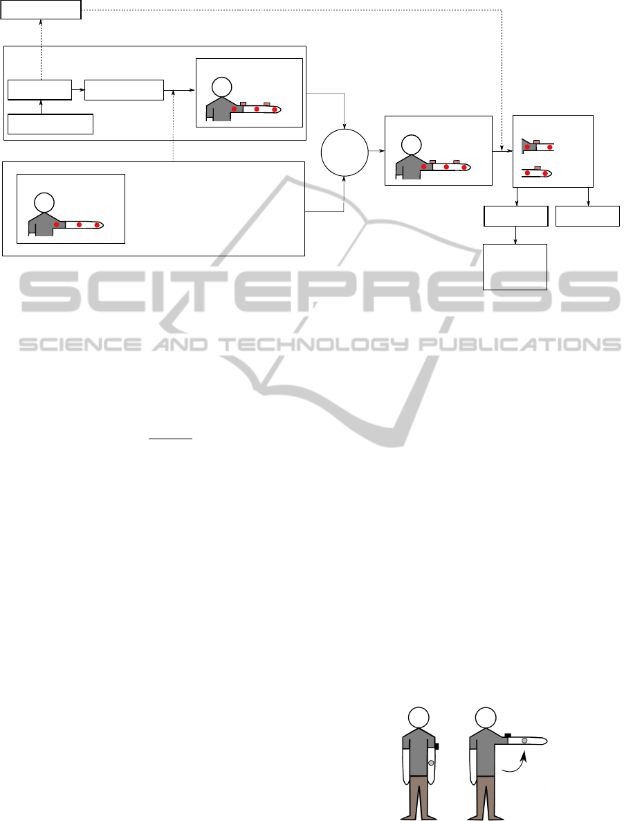
The data delivered by the 3D depth sensor in the
Microsoft Kinect is accessed using the Microsoft
Hand
Wrist
Elbow
Shoulder
Head
Center of
Spine
Hip
Knee
Ankle
Foot
the shoulder
Center of
the hip
Figure 1: Joint positions described within the Skeleton-
model offered by the Microsoft Kinect sensor.
SDK. Data is accessed with a sampling rate of 30
Hz and the SDK is able to track the motion of up to
four persons simultaneously. The SDK provides the
tracking information of each person as 20 absolute
3D position coordinates of the joints shown in the
skeleton model in Fig. 1.
IMU 1
IMU n
Madgwick
Data
Kinect
Joint
Size
orientation
orientation
pose
estimated pose
estimated pose
Filter
Madgwick
Filter
Fusion
Extraction
Determination
Figure 2: Flowchart of the data fusion algorithm.
Like most sensors, IMUs and the Kinect sensor
are not immune to measurement artifacts. Besides the
presence of drift, other events (such as rapid move-
ments, occlusions, disturbance in the Bluetooth com-
munication, optical or magnetic noise, etc.) can lead
to faulty or missing measurement data from one of
both sensors. In the present work we try to compen-
sate for drift as well as missing or faulty data using an
algorithm that fuses information from IMUs and the
Kinect. To fuse the data we developed an algorithm
(Fig. 2) that uses an embedded Kalman Filter. We
explain the algorithm next.
We will explain the fusion algorithm using an ex-
ample of tracking a human upper and lower arm (Fig.
3). For this example, the 3D joint positions of the el-
bow P
I
n1
and the wrist P
I
n2
are tracked using two IMUs
MotionCapturingwithInertialMeasurementUnitsandKinect-TrackingofLimbMovementusingOpticalandOrientation
Information
121

P
I
n
= P
K
n
P
I
n1
P
I
n2
m1
m2
~o
m1
~o
m2
l
1
l
2
Figure 3: Derivation of joint positions P
I
n1
and P
I
n2
using
two IMUs m1 and m2. The length l1 and l2 as well as the
initial joint positions P
K
n
are provided by the Kinect.
m1 and m2. The initial shoulder coordinate P
I
n
is taken
from the corresponding position coordinate P
K
n
ac-
quired by the Kinect. Using the quaternion represen-
tation that results from processing the IMU data with
the Madgwick filter, the vector ~o
m
, which describes
the direction the front side of the IMU is looking at
(commonly known in graphics as lookAt vector, see
Fig. 3), can be determined. Based on the vector ~o
m
and the known length of the upper arm l
1
and lower
arm l
2
the joint positions can be determined. First the
unit orientation vectors of the 2 IMUS ~o
m1
and ~o
m2
are multiplied by the length of the upper and lower
arm.
−→
p
m1
=
−→
o
m1
· l
1
,
−→
p
m2
=
−→
o
m2
· l
2
(2)
With the addition of the resulting vector p
m1
to the
initial shoulder coordinate P
I
n
, the position of the el-
bow joint P
I
n1
can be determined. The calculation of
the wrist joint position P
I
n2
can then be determined by
adding p
m2
to the now known elbow coordinate P
I
n1
.
−−→
OP
I
n1
=
−−→
OP
I
n
+
−→
p
m1
,
−−→
OP
I
n2
=
−−→
OP
I
n1
+
−→
p
m2
(3)
The 3D coordinates of the elbow and wrist positions
are used for the Kalman filter. In the next step the
Kinect data is prepared. As mentioned before, the
Kinect measures the absolute 3D coordinates of 20
joint positions of every tracked person. These joint
positions are used inside the Kalman filter to ad-
just the correspondent joint positions obtained by the
IMUs. The corrected, fused results of the Kalman fil-
ter are fed back to the Madgwick filter to compensate
for existing orientations errors.
The Kalman filter is determined using basic
knowledge from (Wendel, 2007), (Koehler, 2005) and
(Jekeli, 2001). The fundamental equations unfold as
follows:
x
−
n/n1/n2/...
=
x
s
y
s
z
s
= A ·
x
i
y
i
z
i
+ v (4)
y
n/n1/n2/...
=
x
m
y
m
z
m
= H ·
x
k
y
k
z
k
+ w (5)
where (4) describes the system state x
−
n/n1/n2/...
as the
true position in space (x
s
,y
s
,z
s
)
T
obtained by multi-
plying the parameter matrix A with the coordinates
P
I
n/n1/n2/...
= (x
i
,y
i
,z
i
)
T
calculated in (3) and the cor-
related noise v. The measurement model (5) de-
scribes the vector of true position y
n/n1/n2/...
in space
(x
m
,y
m
,z
m
)
T
obtained by multiplying the parameter
matrix H with the joint position data of the Kinect
P
K
n/n1/n2/...
= (x
k
,y
k
,z
k
)
T
and the correlated noise w.
A and H are the usual parameter matrices of a Kalman
filter. For our simple implementation, we used unit
matrices for A and H.
The Kalman-Gain K is described in (6) where P is
the covariance of the IMU and R is the covariance of
the Kinect. For a detailed derivation see (Maybeck,
1982).
K = P · H
T
(H · P · H
T
+ R)
−1
(6)
As reference values for the covariances, we used val-
ues taken from the datasheets of the IMUs and the
Kinect. After empirical studies, the basic values were
set to R = 0.015m for the Kinect and to P = 0.005m
for the IMU. The covariance R of the Kinect is dy-
namic and changes depending on the tracking state of
the Kinect and on the identified outliers in the calcu-
lated positions. The difference between the last cal-
culated position and the next position received by the
Kinect is described by ∆s. For our applications, we
established as maximum ∆s of 0.15m so that, if the
distance between two consecutive measurements ex-
ceeded 0.15m, the covariance matrix R was recalcu-
lated as follows:
R =
R
x
0 0
0 R
y
0
0 0 R
z
+
∆s
2
x
0 0
0 ∆s
2
y
0
0 0 ∆s
2
z
∗K (7)
where K is empirically set to 15 to obtain best re-
sults. Using the described dynamic covariance ma-
trix R, the system behaves robustly in the presence
of tracking errors produced by the Kinect (Nischwitz
et al., 2007). For each joint n/n1/n2/... both IMU
and Kinect positions are fused in (8) to get the new
position x
+
. Depending on the Kalman-Gain K the
data gets weighted differently in each step.
x
+
= x
−
· K · (y − H ·x
−
) (8)
The resulting positions provided by the Kalman
filter are then used to create a fused rotation matrix M
for each tracked limb. To create M we need three vec-
tors, v
f ront
, v
up
and v
side
, which respectively describe
BIODEVICES2014-InternationalConferenceonBiomedicalElectronicsandDevices
122
Quaternions
lookAt Vectors
Kalman
Kinect coordinates
P
K
n
,P
K
n1
,P
K
n2
P
I
n
,P
I
n1
,P
I
n2
IMU
Kinect
l
1
,l
2
Rotationmatrix
v
up
IMU coordinates
Fused coordinates
Rotationmatrix
filter
M
~o
m1
, ~o
m2
P
K
n
P
I
n
,x
+
n1
,x
+
n2
M
1
M
2
Quaternions 3D Avatar
Madgwick
Correct
filter
Madgwick filter
Figure 4: Flowchart of data types and their interactions between each other.
in what directions the front, up and lateral sides of the
IMUs are looking at. The coordinates resulting from
the Kalman filter are used to calculate the unit v
f ront
vector,
~v
f ront
=
−−−→
P
I
n
x
+
n1
k
−−−→
P
I
n
x
+
n1
k
(9)
The vector v
up
needed for the fused rotation matrix M
cannot be calculated only from the two joint positions,
but can be extracted from the orientation Quaternions
delivered by the Madgwick Filter. The Quaternion
data from the Madgwick Filter is translated into a ro-
tation matrix (in our case using Microsoft XNA or
OpenGL) from which v
up
gets extracted. ~v
side
can be
calculated out of the cross product of v
f ront
and v
up
:
~v
side
=~v
f ront
×~v
up
(10)
M =
~v
x, f ront
~v
x,side
~v
x,up
~v
y, f ront
~v
y,side
~v
y,up
~v
z, f ront
~v
z,side
~v
z,up
(11)
The fused rotation matrix M is now used to correct the
orientation results of the Madgwick Filter. To do so
the fused rotation matrix M gets converted back into
a Quaternion (in our case using Microsoft XNA or
OpenGL) and replaces the old orientation information
of the Madgwick-Filter.
An overview of the whole process of converting the
different data types and fusing them together can be
seen in Fig. 4.
3 RESULTS
The first step of our evaluation consisted in carrying
out a battery of tests to determine the accuracy of the
proposed system. For these tests, the coordinates of
the right elbow of 10 different test persons were mea-
sured while the test persons were not moving at all.
For each test person a dataset of 1000 measured joint
coordinates of the right elbow was recorded (10s at
a measurement rate of 100Hz). The standard devia-
tion of the resulting joint coordinates of the fusion al-
gorithm compared to the real position was measured.
The evaluation of the measurements provided us with
an average standard deviation of ±1.47cm in the x-
direction, ±1.62cm in the y-direction and ±2.20cm
in the z-direction.
The second step of our evaluation consisted of track-
ing the movement of the arm. For this experiment, a
patient periodically moved his/her tracked arm up and
down as shown in Fig 5. A subset of the Kinect and
IMU measurements of the right elbow position coor-
dinates is shown in Fig 6 and Fig. 7. The Kinect was
Figure 5: Reference exercise of the patient. The gray circle
indicates the tracked elbow position. The black box is the
sensor attached to patients arm.
MotionCapturingwithInertialMeasurementUnitsandKinect-TrackingofLimbMovementusingOpticalandOrientation
Information
123
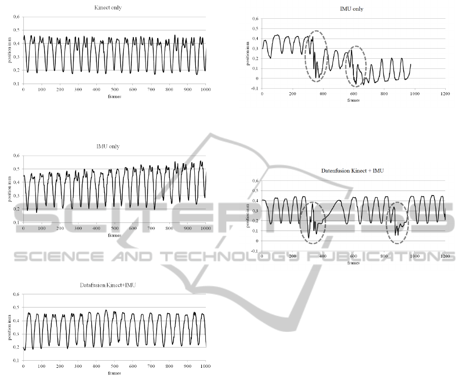
Figure 6: Tracked x-coordinates by the Kinect while the
patient is moving his/her arm periodically up and down.
Figure 7: Tracked x-coordinates by the IMU while the pa-
tient is moving his/her arm periodically up and down.
Figure 8: Resulting x-coordinates of the fusion algorithm
while the patient is moving his/her arm periodically up and
down.
able to track the elbow without any noticeable drift
while the acquired data from the IMU shows some
drift (0.1mm in 10 s). As shown in Fig. 8 the oc-
curring drift while tracking the elbow movement is
removed in the fused data.
Several problems appear when acquiring move-
ment data with the Kinect sensor. The most com-
mon issue observed occurs whenever body parts of
the tracked person are hidden from the sensor or are
out of the range of sensing. If this happens, the algo-
rithm provided by Microsoft marks appropriate joints
with the state not visible. While in this state, joint po-
sitions cannot be recognized. During such a phase the
fusion algorithm passes on the Kinect data and uses
only IMU coordinates. From our experimental results
we could establish that our IMU presented an average
drift of approximately 0.01mm/s. From this measure-
ment, and depending on the precision required by a
Figure 9: Tracked x-coordinates by the IMU while the pa-
tient is moving his/her arm periodically up and down. The
abrupt movements that cause errors within the Madgwick-
Filter are marked by gray dashed circles.
Figure 10: Resulting x-coordinates of the fusion algorithm
while the patient is moving his/her arm periodically up and
down. The abrupt movements that cause errors within the
Madgwick-Filter are marked by gray dashed circles.
particular application, we can establish an experimen-
tal Kinect time-out window. That is, the maximum
amount of time that we can pass on the Kinect mea-
surements while still holding the IMU measurements
stable. For example, if a precision of 1mm in the mea-
surement of joint coordinates is required, we need to
perform sensor data fusion at least every 100s.
The third step of our evaluation consisted again of
tracking a periodic elbow movement, only this time
the patient would occasionally move the arm fast and
abruptly. Fig. 9 shows the x-coordinates of an IMU
tracked elbow in this scenario. While periodically
moving the arm, the patient introduces intentional er-
rors by moving his/her arm way too fast for the IMU
to track. These moments are marked by gray dashed
circles. After the forced errors the patient continues
his/her periodic movement normally. The fast move-
ments cause the Madgwick filter to calculate a wrong
orientation of the IMUs placed on the arm of the pa-
tient. Therefore the calculated position coordinates
are incorrect. In Fig. 10 the same experimental results
are shown after fusing the IMU data with the Kinect
data. As can be seen, the orientation error of the IMU
gets corrected within three to four cycles of move-
ment after the error occurred. In a fourth step of our
evaluation protocol, we tried to evaluate if the fusion
algorithm could compensate for artifacts in the Kinect
BIODEVICES2014-InternationalConferenceonBiomedicalElectronicsandDevices
124
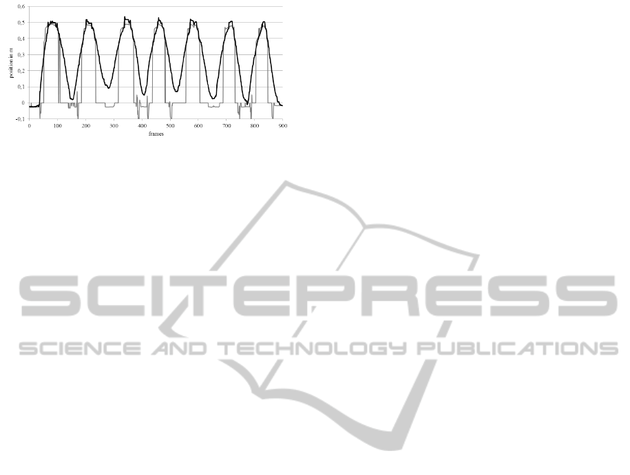
Figure 11: The black curve shows the resulting x-
coordinates of the fusion algorithm while the vision of the
Kinect is disturbed. The corresponding Kinect coordinates
are shown in the gray curve. While this curve is at zero, the
Kinect is not able to detect the joint and with that, it does
not provide data for the fusion algorithm.
measurements. For this step, the same experiment of
moving the arm periodically up and down was per-
formed. Fig. 11 shows the x-coordinates of the wrist
position obtained from the fusion algorithm in black
and from the Kinect in gray. During this exercise the
view of the Kinect was periodically obstructed on pur-
pose. While the gray curve is on zero, the Kinect
doesn’t see the wrist and is not able to deliver any
data to the fusion algorithm. As can be seen, missing
Kinect data over a short time is compensated for us-
ing only IMU data. An important aspect to maintain
the stability of the Kinect measurements even in the
presence of periodic obstructions is the possibility to
dynamically recalculate the covariance of the Kinect
as shown in (7).
The last step in our evaluation protocol was
a first, exploratory measurement done in a single
Parkinson patient. We wanted to qualitatively assess
if the high accuracy of the IMU measurements make
them suitable to track very small movements such as
tremor in Parkinson disease. The proposed system
was in fact able to detect the Parkinson tremor
without drift during a 10 minute experiment.
4 CONCLUSIONS
In this paper we propose a novel algorithm to carry
out sensor data fusion. In particular, we fuse data
obtained from IMUs and the Kinect while tracking
limb movement. Our fusion algorithm uses the Madg-
wick filter as part of a control loop, a Kalman filter to
fuse information and quaternion correction to main-
tain stability of the measurements. A battery of initial,
exploratory experiments allowed us to assess that the
fusion of data from the IMUs and the Kinect provide
increased precision and stability for movement track-
ing. We could also assess that data fusion was able to
correct errors in the measurements either by dropping
faulty measurements or by relying only on one sensor
when data from the second one was unavailable.
In (Obdrzalek et al., 2012) the accuracy of the
Kinect sensor was examined. The authors wanted to
determine if the Kinect meets the requirements for
medical posture analysis. During their investigations,
they observed a standard deviation of the joint coordi-
nates measured by the Kinect of ±5.5cm. In our ex-
periments with sensor data fusion we observed a stan-
dard deviation of the joint coordinate measurements
of ±2.20cm, which, while encouraging, is still very
low compared to high end optical tracking systems.
As part of the research carried out in (Jung et al.,
2010) a system of IMUs was used for motion analysis.
The IMUs were used to record and display postures
and movements of the upper body. However, this was
only possible with a limited mobility of the patient
and an additional individual calibration of the IMUs.
By comparison, the introduction of the Kinect sensor
in our experiments allowed for higher flexibility in the
movements without the need to recalibrate the IMUs
for each patient.
To fully evaluate the capabilities of the proposed
system in medical applications, we need to carry out
additional studies on larger groups of patients, differ-
ent locations and different types of movements. Fur-
ther studies are also needed to better outline the lim-
itations of the developed application and improve the
overall system. A quantitative study using controlled
movements in a robotic arm could be used to precisely
quantify the precision of the tracking algorithm pro-
posed. In future work we want to use the system to
track multiple persons, record therapy processes and
support clinical evaluation of diseases such as Parkin-
son.
ACKNOWLEDGEMENTS
The authors would like to thank Karl Dubies and
Michael Stuber for their assistance. This work was
supported by a grant from the Ministry of Science,
Research and the Arts of Baden-Wuerttemberg (Az:
33-7533-7-11.6-10/2).
REFERENCES
Bo, A., Hayashibe, M., and Poignet, P. (2011). Joint an-
gle estimation in rehabilitation with inertial sensors
and its integration with kinect. In Engineering in
Medicine and Biology Society,EMBC, 2011 Annual
International Conference of the IEEE, pages 3479–
3483.
MotionCapturingwithInertialMeasurementUnitsandKinect-TrackingofLimbMovementusingOpticalandOrientation
Information
125

Claasen, G., Martin, P., and Picard, F. (2011). High-
bandwidth low-latency tracking using optical and in-
ertial sensors. In Automation, Robotics and Applica-
tions (ICARA), 2011 5th International Conference on,
pages 366–371.
Cloete, T. and Scheffer, C. (2008). Benchmarking of a full-
body inertial motion capture system for clinical gait
analysis. In Engineering in Medicine and Biology So-
ciety, 2008. EMBS 2008. 30th Annual International
Conference of the IEEE, pages 4579–4582.
Cordella, F., Di Corato, F., Zollo, L., Siciliano, B., and Van
Der Smagt, P. (2012). Patient performance evaluation
using kinect and monte carlo-based finger tracking. In
Biomedical Robotics and Biomechatronics (BioRob),
2012 4th IEEE RAS EMBS International Conference
on, pages 1967–1972.
El-laithy, R., Huang, J., and Yeh, M. (2012). Study
on the use of microsoft kinect for robotics applica-
tions. In Position Location and Navigation Sympo-
sium (PLANS), 2012 IEEE/ION, pages 1280–1288.
Fischer, C., Talkad Sukumar, P., and Hazas, M. (2012). Tu-
torial: implementation of a pedestrian tracker using
foot-mounted inertial sensors. Pervasive Computing,
IEEE, PP(99):1–1.
Glaz, Y. L. (2011). Smartphonebasierte bewegungsanalyse
zur therapiekontrolle bei morbus parkinson. Master’s
thesis, University of Applied Sciences Hochschule
Ulm.
Jekeli, C. (2001). Inertial Navigation Systems With Geode-
tic Applications. Walter de Gruyter.
Jung, Y., Kang, D., and Kim, J. (2010). Upper body mo-
tion tracking with inertial sensors. In Robotics and
Biomimetics (ROBIO), 2010 IEEE International Con-
ference on, pages 1746–1751.
Koehler, B.-U. (2005). Konzepte der statistischen Sig-
nalverarbeitung. Springer, Berlin [u.a.].
Liguo, H., Yanfeng, Z., and Lingyun, Z. (2011). Body mo-
tion recognition based on acceleration sensor. In Elec-
tronic Measurement Instruments (ICEMI), 2011 10th
International Conference on, volume 1, pages 142–
145.
Madgwick, S., Harrison, A. J. L., and Vaidyanathan, R.
(2011). Estimation of imu and marg orientation us-
ing a gradient descent algorithm. In Rehabilitation
Robotics (ICORR), 2011 IEEE International Confer-
ence on, pages 1–7.
Maybeck, P. (1982). Stochastic Models, Estimation, and
Control. Mathematics in science and engineering.
Academic Press.
Nischwitz, A., Fischer, M., and Haber
¨
acker, P. (2007).
Computergrafik und Bildverarbeitung. Vieweg, Wies-
baden, 2 edition.
Obdrzalek, S., Kurillo, G., Ofli, F., Bajcsy, R., Seto, E.,
Jimison, H., and Pavel, M. (2012). Accuracy and ro-
bustness of kinect pose estimation in the context of
coaching of elderly population. In Engineering in
Medicine and Biology Society (EMBC), 2012 Annual
International Conference of the IEEE, pages 1188–
1193.
Patsadu, O., Nukoolkit, C., and Watanapa, B. (2012). Hu-
man gesture recognition using kinect camera. In Com-
puter Science and Software Engineering (JCSSE),
2012 International Joint Conference on, pages 28–32.
Rodriguez-Angeles, A., Morales-Diaz, A., Bernabe, J.-
C., and Arechavaleta, G. (2010). An online inertial
sensor-guided motion control for tracking human arm
movements by robots. In Biomedical Robotics and
Biomechatronics (BioRob), 2010 3rd IEEE RAS and
EMBS International Conference on, pages 319–324.
Taffoni, F., Piervirgili, G., Formica, D., and Guglielmelli, E.
(2011). An alignment procedure for ambulatory mea-
surements of lower limb kinematic using magneto-
inertial sensors. In Engineering in Medicine and Bi-
ology Society,EMBC, 2011 Annual International Con-
ference of the IEEE, pages 1197–1200.
Walter, B. (2012). Smartphonebasierte bewegungsanalyse
zur therapiekontrolle bei morbus parkinson. Master’s
thesis, University of Applied Sciences Hochschule
Ulm.
Wendel, J. (2007). Integrierte Navigationssysteme : Sen-
sordatenfusion, GPS und Inertiale Navigation. Old-
enbourg, Muenchen [u.a.].
Xiao, Z., Mengyin, F., Yi, Y., and Ningyi, L. (2012).
3d human postures recognition using kinect. In In-
telligent Human-Machine Systems and Cybernetics
(IHMSC), 2012 4th International Conference on, vol-
ume 1, pages 344–347.
Zeng, M., Liu, Z., Meng, Q., Bai, Z., and Jia, H. (2012).
Motion capture and reconstruction based on depth in-
formation using kinect. In Image and Signal Process-
ing (CISP), 2012 5th International Congress on, pages
1381–1385.
Zhang, Z., Fang, Q., and Ferry, F. (2011). Upper limb
motion capturing and classification for unsupervised
stroke rehabilitation. In IECON 2011 - 37th Annual
Conference on IEEE Industrial Electronics Society,
pages 3832–3836.
BIODEVICES2014-InternationalConferenceonBiomedicalElectronicsandDevices
126
