
Low Power Remote Neonatal Temperature Monitoring Device
Hiteshwar Rao
1
, Dhruv Saxena
1
, Saurabh Kumar
3
, Sagar G. V.
1
, Bharadwaj Amrutur
1,2
, Prem Mony
4
,
Prashanth Thankachan
4
, Kiruba Shankar
4
, Suman Rao
5
and Swarnarekha Bhat
5
1
Robert Bosch Center for Cyber Physical Systems, Indian Institute of Science, Bangalore, India
2
Department of Electronics and Communication Engineering, Indian Institute of Science, Bangalore, India
3
Department of Instrumentation and Applied Physics, Indian Institute of Science, Bangalore, India
4
Division of Epidemiology and Population Health, St. John’s Research Institute, Bangalore, India
5
Department of Neonatology, St. John’s Medical College Hospital, Bangalore, India
Keywords:
Neonatal Monitoring, Wearable Sensors, Telemedicine, Body Sensor Network, Temperature Measurement,
Temperature sensors, Skin Temperature, Noninvasive Wearable Wireless Monitoring System, Biomedical
Measurements.
Abstract:
In this paper we present the design of a wearable temperature sensing device for remote neonatal monitoring.
It is designed for continuous and real-time monitoring of the infants in remote rural areas, for the first few
weeks after their birth. It is capable of sensing the neonate’s skin temperature with 0.1
◦
C accuracy to detect
the early onset of hypothermia. The sensed data is transferred securely over bluetooth low energy radio to a
nearby gateway, which then relays the information to a central database for real time monitoring. The device
incorporates a medical grade thermistor which is directly interfaced to a microcontroller with an integrated
bluetooth low energy radio. Low power optimizations at both the circuit and software levels ensure sleep
currents of only 1uA, ensuring very long battery life. The device is packaged in a baby friendly, water proof
housing and is easily sterilizable and reusable.
1 INTRODUCTION
Neonatal Mortality Rate (NMR)(WHO et al., 2012) is
defined as number of newborn deaths (that is within
the first 28 days of life) per thousand births. The
global neonatal deaths today account for more than
40% of all child deaths before the age of five and is
estimated to be more than 8 million(Oestergaard and
Inoue, 2011). More than 95% of these deaths occur in
developing nations like regions of Africa and South
Asia. Reports(Global Health, 2010) have shown that
India has about 10 times higher NMR compared to the
western world. NMR in India was 31 as of 2011, a
33% decrease in NMR since 1990, yet taking into ac-
count its burgeoning population, approximately1 mil-
lion newborn died in 2010, nearly 30% of the global
neonatal deaths(WHO, 2012).
Recent research indicates that hypothermia is in-
creasingly considered as a major cause of neonatal
morbidity and mortality, especially in rural resource
constrained settings(Kumar et al., 2009)(Kumar et al.,
2008). Hypothermia for neonates is defined as an
aberrant thermal state of diminution of their body’s
temperature below 36.5
◦
C. Further decrease in body
temperature causes respiratory depression, acidosis,
decreases the cardiac output, decreases the platelet
function, increases the risk of infection and may
even lead to fatality without preemption(Macfarlane,
2006). WHO has classified hypothermia into follow-
ing three categories depending on the body tempera-
ture(WHO, 1993).
• Mild hypothermia: 36.0 to 36.4
◦
C
• Moderate hypothermia: 32.0 to 35.9
◦
C
• Severe hypothermia: < 32
◦
C
In newborns, hypothermia can be caused by loss of
body heat to surroundings through conduction, con-
vection, radiation or evaporation. Premature new-
borns are even more susceptible to these factors be-
cause of their low weight at the time of birth, they
have a large ‘surface area to weight ratio’ with min-
imal subcutaneous fat. They have poorly devel-
oped shivering, sweating and vasoconstriction mech-
anisms and they are unable to retain their body’s
heat(Macfarlane, 2006). Hypothermia has a wider
spread in the developing nations. In the rural context
28
Rao H., Saxena D., Kumar S., G. V. S., Amrutur B., Mony P., Thankachan P., Shankar K., Rao S. and Bhat S..
Low Power Remote Neonatal Temperature Monitoring Device.
DOI: 10.5220/0004798300280038
In Proceedings of the International Conference on Biomedical Electronics and Devices (BIODEVICES-2014), pages 28-38
ISBN: 978-989-758-013-0
Copyright
c
2014 SCITEPRESS (Science and Technology Publications, Lda.)

thermal care of newborn is often overlooked and hy-
pothermia goes undetected. The most prevalent tech-
nique in rural settings on which caregivers rely is hu-
man touch, which is less sensitive and is not a reli-
able method. Commonly used mercury thermometers
are often fragile and require some degree of training.
Hence there is a need for an automated and robust
way of measuring the neonate’s temperature on a con-
tinuous basis, and be able to initiate intervention in a
prompt manner as required. This has been the main
motivation towards developing the temperature mon-
itoring device and system.
The ever increasing cost for state-of-the-art medi-
cal facilities like NICU(Neonatal Intensive Care Unit)
impedes the user from accessing it in rural areas. The
problem is exacerbated in rural parts as India’s popu-
lation is still largely rural, with limited or no access to
modern health care infrastructure. Mothers are often
discharged earlier and infants are taken home right af-
ter delivery. In some cases delivery is even carried out
at their residence without any medical professional or
facilities at their disposal. We would like to capitalise
the technical advancementsof 21st century to perform
remote neonatal healthcare monitoring in an econom-
ical manner.
In this paper, we propose a novel wearable
monitoring device, designed and developed for the
neonates in remote, rural and resource constraint set-
tings. Our objective is to develop an ultra low power
wireless skin temperature sensor, capable of monitor-
ing newborns’ body temperature unobtrusively and in
real time over a span of the first few days to weeks.
Sensed temperature data will be securely uploaded via
a gateway device to a centralised database. Analytics
on the temperature data will be run to determine the
intervention needed in case of temperature excursions
beyond normal levels. This system will be given to
new mothers to take home after delivery.
However this will require solutions to a number
of significant challenges like ultra low power sensing,
device integration and packaging, ultra low power
short haul communication and baby friendly design.
1.1 Requirements and Challenges
We conducted a user study in the NICU of St. John’s
Medical College Hospital in Bangalore, India. The
study involved understanding the current techniques
and equipment used in NICU to monitor the health
of the neonates. This led to understandings in how
the neonates are handled and how their vital parame-
ters such as body temperature are measured. It also
revealed concerns of the doctors regarding current
equipment and the feasibility of use of such equip-
ment in a remote rural setting. Issues like placement
of the sensor on the body, ability of the device to be
sterilised and other aspects which will be highlighted
in the coming sections, were dealt with through brain-
storming sessions and concept generation. Feedback
from the doctors/neonatologists was taken time and
again on the concepts generated which led to a more
concrete list of requirements.
1.1.1 Safety
In an NICU setting neonates are kept under radi-
ant warmers to regulate their body temperature. To
achievethis, neonates’ body temperature is constantly
monitored by employing conventional temperature
probes, attached to their skin with adhesive tape as
shown in figure 1.
Figure 1: Neonate kept under radiant warmer in NICU at
St. John’s Medical College Hospital.
The skin of neonates is extremely delicate and
vulnerable to environmental stress. Research(Susan
et al., 2001) has shown that increase in microbial
growth under temperature probe can be harmful.
Medical tape causes irritation and when it is removed
it causes skin abrasion and damage(Rutter, 2000).
Risk of the damage of internal organs involved with
the tympanic and rectal temperature measurement
limits their use for continuous monitoring. Thus the
primary concern and requirement is their protection,
safety and non-invasive monitoring.
For continuous measurement of body temperature
the safest potential location for the sensor is over the
right upper quadrant of the abdomen just below the
rib-cage.
1.1.2 High Accuracy
For monitoring hypothermiaor hyperthermia,temper-
ature measurement accuracy should be same as that
of medical grade NICU temperature probes. Thus an
high accuracy of 0.1
◦
C should be achieved in a re-
mote rural setting.
1.1.3 Longer Battery Life
Once the device is installed and given to the user,
neonates should be continuously monitored for the
LowPowerRemoteNeonatalTemperatureMonitoringDevice
29

duration of first 2 to 3 weeks, with a sampling period
of once every 15 minutes. Battery should last long
enough without any need for charging or replacement.
This calls for an ultra low power design to meet the
requirement of longer battery life.
1.1.4 Robustness
The device needs to unobtrusively operate for several
days. During the operation in remote regions, manual
intervention for maintenance or repair is difficult to
provide. Hence the device should be robust enough to
cater to challenges like shock, vibration, and should
not get reset accidentally. It should be hermetically
sealed to protect the electronics from getting dam-
aged in case liquids seep in during sterilisation or due
to contact with body fluids (e.g sweat, urine, faeces,
etc.). Moreover, the device should be adjustable so
that it can used on neonates of different abdominal
girths, it should be aesthetically pleasant and should
be baby friendly.
Detailed description of the solution to these re-
quirements and challenges is provided in section 2.3
1.2 Related Works
In India, remote rural health monitoring is being en-
abled by many companies and government agencies.
For instance, in (Neurosynaptics, 2002), the com-
pany has developed a health kiosk and system called
ReMeDi, which is deployed at the primary health cen-
ter. The Kiosk allows a number of basic health tests
to be conducted, the results of which are communi-
cated over the cellular network to a central repository
which keeps track of patient health data. This system
is in use in a number of rural districts in Bihar and
parts of Karnataka. Many other similar systems are
being developed and deployed by various NGOs and
startups across India.
Studies indicate that monitoring certain basic pa-
rameters, like temperature, could help indicate im-
pending problems and hence with timely interven-
tion, perhaps the mortality can be reduced. In this re-
gard, an innovative product, for keeping babies warm,
has been developed by a startup called Embrace (Em-
brace, 2012).
In a related work, authors in(Chen et al., 2010)
describe some sensors and packaging which has been
developed for monitoring new borns. The sensors
are embedded in a smart jacket, with careful attention
paid to the baby friendliness of the design.
Another device(iThermometer, 2012) addresses a
similar application where temperature of body can
be measured and transmitted wirelessly to an android
platform based device.The device has a battery life of
only 48 hours and a relatively larger size as compared
to our design.
The authors in (Isetta et al., 2013), report an in-
ternet based health monitoring system for newborns.
The parents fill up an online form with some data
about their babies regularly. These include: Weight,
body temperature, sleeping patterns, skin color, feed-
ing etc. The remote nursing staff monitor these pa-
rameters and provide timely advice. The authors con-
ducted a clinical research study for the efficacy of this
system and found that it helped reduce the number of
visits to the hospital by a factor of 3 for the babies be-
ing monitored via this system, as compared to a con-
trol group, which did not use it. This study encour-
ages us to develop automated monitoring techniques
like in (Chen et al., 2010) which will be more reliable
and efficient than manually entering the data.
2 SYSTEM DESIGN
This section describes the design decisions involved
in developing the hardware platform and the proto-
type device
2.1 Wireless Communication
There are many low-power wireless technologies like
Bluetooth low-energy(BLE), Bluetooth classic, ANT,
ZigBee, Wi-Fi, Nike+, IrDA, and the near-field com-
munications (NFC) standards currently being em-
ployed in the field of healthcare.
For our application, the following critical key pa-
rameters drove the selection of the wireless interface:
ultra-low-power, low cost, small physical size, appli-
cation’s network topology requirements and security
of communication.
The authors in (Artem et al., 2013) do a power
consumption analysis of BLE, ZigBee and ANT sen-
sor nodes in a cyclic sleep scenario and find BLE to
be the most energy efficient. We believe that in the
next few years, millions of mobiles and computers
will support BLE, thus enabling BLE based sensors to
utilize these as gateways to the internet ((Alf Helge,
2010) and (Gomez et al., 2012)). We already see
commercial products with BLE like FitBit (Hawley E
et al., 2012), Pebble Watch and Hot Watch, and hence
it encourages us to leverage the advantages of em-
ploying BLE as the short-range wireless communica-
tion technology for connecting the sensor to the gate-
way.
BIODEVICES2014-InternationalConferenceonBiomedicalElectronicsandDevices
30
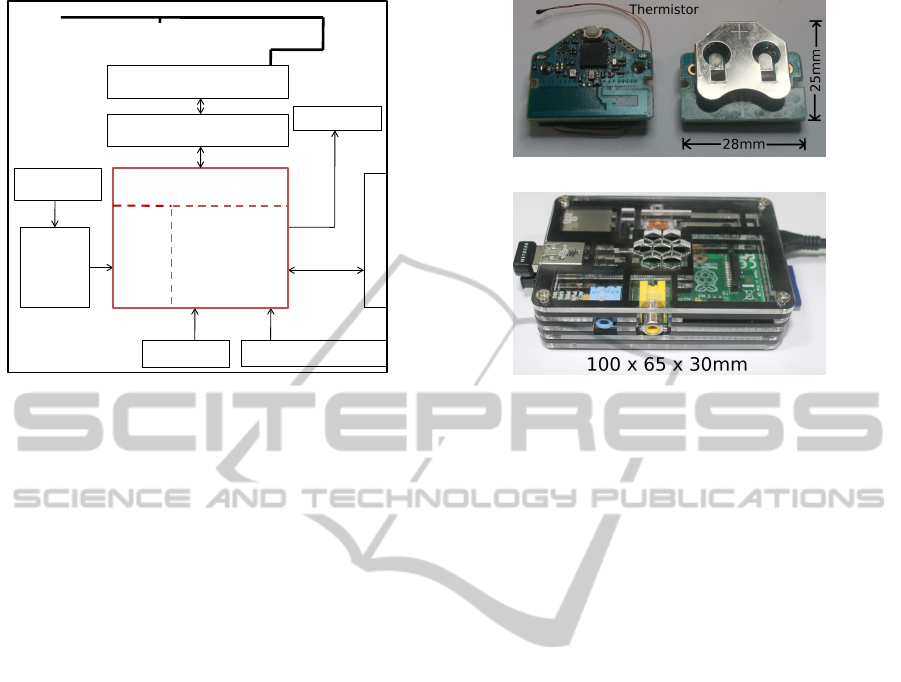
AES-128
Xtals
Status LEDs
3volt Coin Cell
Thermistor
Impedance Matching
Embedded Inverted F antenna 2.4 GHz
Analog
Front
End
Programming Interface
Balun Filter
8051 +
Bluetooth 4.0
12
Bit
ADC
CC2540
Figure 2: Block diagram of the temperature sensor.
2.2 Hardware Platform
2.2.1 Sensor Platform
A monolithic design of sensor platform is required to
minimize the form factor, facilitate ease of manufac-
turing and to reduce the overall cost of the product.
Hence a custom made platform has been developed
using a multilayer Printed Circuit Board. The assem-
bled sensor platform has a dimension of 28 mm x 25
mm x 8 mm.
The sensor hardware platform as shown in Fig-
ure 2a and consists of a Microcontroller(MCU) with
integrated Bluetooth 4.0(BLE) and a 12-bit ADC
(CC2540 from Texas Instruments), the NICU grade
temperature sensor with its analog front end circuit,
status LEDs, power supply and RF balun filter and an-
tenna for wireless communication over 2.4 GHz ISM
band. The microcontroller system has 256 KB pro-
grammable flash memory and 8-KB RAM and sup-
ports very low-power sleep modes, with sleep current
as low as only 0.4µA. There is built-in 128-bit hard-
ware AES support for secure communication.
Sensor hardware can be programmed wirelessly
and application programs can be downloaded on
MCU’s flash over the air via mobile or a gateway de-
vice. This feature enables us to dynamically control
the sensor platform without having to disassemble the
module and remove it from the package.
High precision MF51E NTC thermistors (Can-
therm, 2009) are used for extremely accurate temper-
ature measurements. These are especially designed
and calibrated for medical equipment. The extremely
small size of thermistor allows it to respond very
quickly to small variations in temperature.
(a) Top and bottom view of the sensor
(b) “Raspberry pi” as a gateway device
Figure 3: Hardware platforms.
The temperature profile running on sensor meets
the universal standard of body temperature profile de-
fined by Bluetooth SIG (Bluetooth, 2012). Hence our
sensor device can communicate to any authenticated
host independent of the gateway platform being used.
2.2.2 Antenna Selection and Performance
The antenna for the sensor device has to balance be-
tween small size and efficiency. High efficiency an-
tenna enables larger separation between the sensor de-
vice and the gateway - thus simplifying the usage sce-
nario. On the other hand, larger size impacts the over-
all device size which is not desirable for a wearable
device. A chip antenna offers a very small footprint
solution but leads to a compromise of some critical
parameters, such as:
• Reduced efficiency (or gain)
• Shorter range
• Smaller useful bandwidth
• More critical and difficult tuning
• Increased sensitivity to components and PCB
• Increased sensitivity to external factors
Detuning of chip antenna happens due to its proxim-
ity with ground plane, power source, plastic enclo-
sure and the condition whether it is worn by the user
or not. Our experiments with the chip antenna indi-
cated an effective range of only about 3 meters. To
overcome these issues, we have used an embedded
Inverted F-antenna (IFA). Performance and character-
istics of both the antennas are tabulated below.
The Inverted-F Antenna has higher efficiency,
longer range and a wider bandwidth than a chip an-
tenna, though larger in size. For our device, the coin
LowPowerRemoteNeonatalTemperatureMonitoringDevice
31

Table 1: Comparison of chip antenna and Inverted-F An-
tenna.
Parameters Chip antenna IFA
Range
†
(m) 3-5 10-12
Bandwidth
∗
(MHz) 100 300
Efficiency
∗
90% 50%
Reflection loss
∗
< 10% > 50%
Cost Low Nil
Size (mm) 8 x 6 25.7 x 7.5
†: Measured in closed indoor enviroment
∗: Obtained from dataheet(TI, 2008)
cell was another size limiting factor and hence we
found this to be a good choice which provides high
performance at a very low cost.
2.2.3 Low Power Analog Front End
Conventional thermistor interfacing techniques
(Boano et al., 2011) use a linearization circuitry
followed by a gain stage(G) and finally a ADC(A)
as shown in figure 4(b). We could eliminate most of
these components in our approach shown in figure
4(a), by using the high precision thermistor, a high
precision low tolerance low temperature coefficient
resistor R
1
and the high resolution 12 bit ADC in the
CC2540. Thanks to the well defined Temperature -
Resistance characteristics of the thermistor the non-
linearity can be taken care of by solving following
log-polynomial Steinhart-Hart equation in software.
1
T
= A+ Bln(R
Th
) +C(ln(R
Th
))
3
(1)
A, B, and C are the Steinhart-Hart coefficients
which are provided by the manufacturer (Cantherm,
2009). This non linearity correction can be done ei-
ther in the gateway or the sensor, thus incurring no
power penalty on the sensor device itself.
The minimum voltage resolution for the 12 bit
ADC operating at full range of 0−3V is 0.732mV. For
the use case in which the sensor module will be em-
ployed, the temperature range lies from 25
◦
C−40
◦
C.
The minimum accuracy requirement within this tem-
perature range is 0.1
◦
C which corresponds to a mini-
mum change of 2.743mV for the sensor module, well
above the LSB of the ADC and hence eliminates the
need for a separate gain stage.
As per the circuit shown in figure 4(a) analog volt-
age reference for 12 bit ADC (M = 12) is also sup-
plied from digital I/O. Therefore the voltage at the in-
put of ADC is given by
V
ADC
=
N
ADC
2
M
V
REF
=
R
Th
R
Th
+ R
1
V
REF
(2)
R
NTC
R
1
10k
R
Th
MCU
Digital I/O
AREF
12-bit ADC
GND
10k
±0.1%
V
ADC
V
REF
(a) new
R
Th
R
1
VCC
GND
G
R
2
R
3
A
GND
(b) conventional
Figure 4: Thermistor interfacing technique.
From above equation R
Th
can be calculated inde-
pendent of the voltage supplied by digital I/O.
R
Th
=
N
ADC
2
M
− N
ADC
R
1
(3)
For the change in R
Th
due to ±1 LSB variation of
ADC and tolerance of R
1
,
∆R
Th
=
R
TH
2
M
∆N
ADC
(2
M
− N
ADC
)N
ADC
+
(N
ADC
)∆R
1
(2
M
− N
ADC
)
(4)
The proposed approach uses a single resistor R
1
with a low temperature coefficient of ±10ppm/
◦
C and
a tolerance of 0.1%. For R
1
= 10KΩ, ∆R
1
is ±10Ω
due to tolerance and ±2Ω due to temperature change
of 20
◦
C. Therefore, total ∆R
1
≈ ± 11Ω. ∆R
Th
due the
change in ±1 LSB of ADC is calculated to be ±10Ω
at 25
◦
C and ±5Ω at 42
◦
C.
From equation 4 the total ∆R
Th
due to ±1 LSB
variation of ADC and tolerance of R
1
is found to be
±15Ω at 25
◦
C and ± 12Ω at 42
◦
C. This corresponds
to an error margin of ±0.03
◦
C at 25
◦
C and ±0.08
◦
C
at 42
◦
C. Error margin is within our accuracy require-
ment. The thermal noise from the resistors are negli-
gible.
The conventional approach suffers from increased
errors due to the number of resistors used because
each has its own temperature dependence and toler-
ance values. Another drawback of the earlier tech-
nique is that current is constantly consumed by the
wheat-stone bridge and the gain stage, irrespective
of the microcontroller being in sleep mode. In the
proposed design, since the sensor interface is pow-
ered from the micocontroller’sGPIO, the current con-
sumption can be significantly reduced by suitably pro-
gramming the GPIO output during the sleep mode.
This is illustrated in the measurements of both the
conventional and the proposed approach in table 2.
The use of well calibrated thermistor and a very
BIODEVICES2014-InternationalConferenceonBiomedicalElectronicsandDevices
32

Figure 6: Prototyped temperature sensor with belts.
300µA
150µA
Sleep Active
New Circuit
Conventional
Figure 5: Current consumption during active and sleep
mode.
Table 2: Current consumption comparison.
Mode New circuit Conventional
Active mode 150µA 300µA
Sleep mode 0µA 300µA
low tolerance resistor eliminates the need for any
other calibrations saving the cost and effort.
2.2.4 Gateway Platform
The sensor communicates with the gateway and
the temperature data is stored on a centralized
database over a secured internet backbone provided
by GPRS/Wi-fi. We have developed the gateway us-
ing both a smartphone (Google Nexus 4) as well as a
low cost platform “Raspberry pi” as shown in figure
3(b). Raspberry pi has a 700MHz ARM core as an
application processor and 512 MB RAM. Dual USB
connectors are used for BLE and Wi-Fi dongles. A
Linux based operating system is booted on it to run
the application program. In the case of the smart-
phone an android application connects to the sensor
and relays the information to the server.
2.3 Prototype and Implementation
The prototype developed includes a casing which
houses the electronics and a belt which is used to fas-
ten the casing around the abdomen of the neonate.
Compared to monolithic design approach of (Chen
et al., 2010) by integrating sensors into textile, our
modular approach of designing a separate belt and
enclosure facilitates the sterilization, assembly, cost
reduction and easier interchangeabilityof the device.
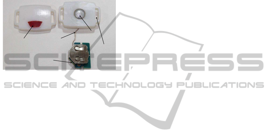
2.3.1 Temperature Sensing Interface
The thermistor has a dimension of 1.6mm x 4mm and
is required to be in thermal contact with the test sur-
face to measure its temperature. However due to the
requirements of the device to be robust and safe for
the neonate (without any sharp/pointy objects stick-
ing out of the device) the sensor was placed in contact
with a thermal interface which would touch the body
of the neonate on one side and house the sensor on the
other side as depicted in Figure 7.
Enclosure
Minimum
protrusion
Aluminum cup
Thermistor
Conductive
Adhesive
Figure 7: Vertical cross-section of the enclosure.
The interface consists of an aluminium cup made
by cold-working of an aluminium sheet. Aluminium
was chosen for its easy formability as well as abil-
ity to retain its shape once it is cold-worked. Alu-
minium also has a very high thermal conductivity
ranging from 200−250 W/m.K, which enables our
thermal interface design to attain thermal equilibrium
with the body of the patient in a short span of time.
The aluminium cold-worked cup is only 0.1mm thick
LowPowerRemoteNeonatalTemperatureMonitoringDevice
33
to minimize the heat loss. To ensure complete ther-
mal contact,the thermistor is glued on the inner side of
the aluminium cup with a highly thermally conductive
copper tape which ensures efficient and quick conduc-
tion of heat from the aluminium surface to the sensing
element. The cup is securely housed inside the casing
while ensuring that it protrudes slightly from the bot-
tom surface of the casing to enable reliable thermal
contact with the body of the patient.
Aluminum
Cup
Silicone
Membrane
Thermistor
Sensor platform
Belt Section
Figure 8: Disassembled prototype.
2.3.2 Power Switch
The device is designed to stay in deep sleep by de-
fault when not operational. To initiate connection es-
tablishment with a BLE gateway, we have provided a
power switch, which needs to be pressed and held for
5 seconds or more. However since the same switch
is also used to reset the device it is placed at a short
depth inside the casing to minimise the chance of ac-
cidental reset. A silicone membrane is flushed with
the top surface of the enclosure such that only if the
membrane is pressed to a depth of 3 mm or more
will the switch get activated. This requires concen-
trated force on the center of the membrane. Exper-
iments were conducted to check if any sort of acci-
dental pressing could lead to such a situation and it
was concluded that only intentional pressing could
achieve such a result. The silicone membrane also
ensures that the casing is water tight.
2.3.3 Enclosure
The enclosure is required to be water tight to pro-
tect the electronics from liquids used for sterilization
as well as from urine. Moreover the casing needs
to be made with minimum number of parts for ease
of production and low cost. The methods for mak-
ing the casing water tight are either to make a sim-
ple lip interface in the design where the top and bot-
tom parts can be pasted, or to go for a more compli-
cated design which involves either snap fits or screw
fittings and requires rubber gaskets to make the de-
vice water tight. The former method although cheaper
to manufacture has the disadvantage that the casing
can only be used one time. However since the de-
vice does not need battery replacement for several
months, the former method seems more feasible given
the fact that even an openable casing will be prone
to damage since it will move from patient to pa-
tient and might eventually be required to be replaced.
The custom designed enclosure as shown in the fig-
ure 6 is rapid-prototyped with the latest and higher
resolution 3-D printing technology (Stratasys, 2013).
The 3-D printed prototype was drop tested from a
height of 2 meters without any damage to the pro-
totype and enclosed circuitry. The actual production
model however would be even more robust due to
higher strength of commonly used injection molding
materials like Polypropylene or Acrylonitrile butadi-
ene styrene(ABS).
2.3.4 Belt Design
Respiration rate for newborns varies from 30−60
breaths per minute and during a respiration cycle the
abdomen region expands and contracts. An increase
in the height of the sternum of around 1/2 cm is con-
sidered as a normal expansion(Scavacini et al., 2007).
Hence the belt has to be designed with the require-
ments of being
• soft and elastic to accommodate the changes in
abdominal circumference during breathing
• able to accommodate different sizes of neonates
• washable for sterilization and reuse
All the above requirementswere met through a de-
sign where the belt is made out of a soft fabric. The
belt has a thin elastic band inside the fabric which can
be elongate upto 3 cms, hence it dynamically allows
for expansion of the belt during breathing. The belt
also has small loops in which fastening velcro can be
attached. The fastening velcro is placed at the ends of
the belt and when the belt folds on itself, the velcro
hooks come in contact with the loops thereby fasten-
ing the belt. This allows for accommodation of differ-
ent sizes of neonates. The fabric is completely wash-
able and the belt can be washed and dried for reuse.
Multiple belts can be assigned for a patient and these
belts can be replaced daily to maintain hygiene.
2.3.5 Baby Friendly Design
The industrial design of the device reflects the face
of a friendly abstract toy, where form follows func-
tion. All features of the face have functional rele-
vance. To keep the number of parts to a minimum,
light gates have been avoided by making the sections
under which the LEDs are housed thinner than the
BIODEVICES2014-InternationalConferenceonBiomedicalElectronicsandDevices
34

Figure 9: Baby friendly enclosure.
overall casing. The thin sections allow light from the
LEDs to be seen well. These sections also give the
appearance of eyes for the face. The membrane for
the switch forms the mouth and the cavities through
which the belt passes give an appearance of ears. This
friendly face appearance of the design could help en-
force confidence in parents that the device is friendly
and is safe for their child. This design was arrived
at after multiple iterations and discussions with the
Neonatologists at SJRI. Initial prototypes were im-
proved through feedback from the Neonatology team
and features like exposed edges, sharp corners and
crevices as well as exposed buttons were removed
and the final design was presented which has been ac-
cepted by the Neonatology team.
3 EVALUATION
This section describes the evaluation method em-
ployed for testing our sensor platform. Experimental
results indicate that the device has the required accu-
racy. Later in the section power calculation is per-
formed to estimate the battery life.
3.1 Experimental Setup
As described in the section 2.3.1 temperature sensing
element is thermally interfaced with aluminium.To
determine the response time and accuracyof the pack-
aged module, experimental setup shown in the figure
10 is used.
A glass beaker filled with 300 ml of water is
placed on a hot plate. An accurate RTD based temper-
ature sensor is placed in the beaker. The temperature
of water is controlled by giving a closed loop feed-
back to hot plate’s heating element. The sensor device
is immersed in water bath along with a bare thermis-
tor. A precision digital thermometer is employed for
setting reference temperature. Packaged devices were
kept immersed in the water bath for 10 hours of con-
tinuous operation and the temperature measurements
Figure 10: Experimental setup.
were logged wirelessly. Temperature readings from
all the sensors were periodically sampled once every
two minutes.
3.2 Results
3.2.1 Responsiveness
Figures 11(a) and 11(b) show the temperature mea-
surements during the experiment. A periodic oscilla-
tion of the temperature waveform was observed, indi-
cating the action of the servo control loop of the hot
plate. The period of the oscillations is approximately
40 minutes and is within ±0.3
◦
C of the temperature
configuration being used.
By definition, responsiveness is the time taken by
the system to respond to an event or a change, hence
these small changes in temperature provides an ideal
environment to determine the response time.
Table 3: Response time and sensivity comparison.
Parameter Bare Reference Packaged
Response < 4sec ≈ 3min ≈ 4min
The bare thermistor is fastest in responsiveness
followed by the reference thermometer and finally the
packaged device. The observed response times are
shown in table 3, indicating that the packaged sen-
sor would take approximately 3−4 minutes to attain
thermal equilibrium with the surroundings. In our ac-
tual application scenario, we are required to take con-
tinuous temperature readings once every 15 minutes,
hence the responsiveness is well within our require-
ment limits.
3.2.2 Accuracy
Using the same configuration for measuring the ac-
curacy, water was heated upto 40
◦
C and then was al-
lowed to cool down to room temperature. Figure 11
LowPowerRemoteNeonatalTemperatureMonitoringDevice
35
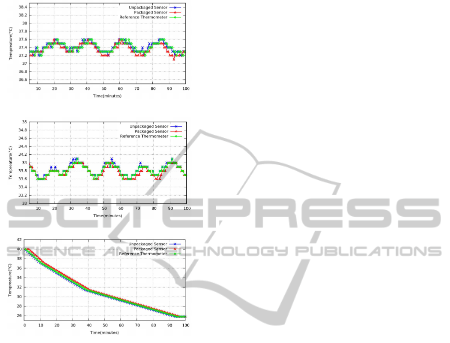
(a) Temp. measurements with hot plate at 37
◦
C
(b) Temp. measurements with hot plate at 34
◦
C
(c) Temperature measurements without hot plate
Figure 11: Responsiveness and accuracy measurement of
the sensor.
(c) shows the logged temperature reading. The vari-
ance (error bar) in the reading from the sensor device
is ±0.04
◦
C. By comparing the data obtained from
the sensor with a high precision digital thermometer
it was calculated that the error was within 0.1
◦
C for
the temperature range of 25
◦
C to 40
◦
C.
3.3 Power Consumption
The sensor device establishes a connection with the
near by gateway device through initial advertisement.
After a successful connection event, the sensor is con-
figured for periodic sleep and data transmission. Fig-
ure 12 and Table 4 shows the measured current and
energy consumed by the device during these modes of
operation. The profile in Figure 12(b) shows typical
power consumption over a sensing cycle. Sleep cur-
rent is measured using 6.5 digit 34411A Agilent mul-
timeter and transient current is measured using hall
effect current probe with TDS5104 Tektronix oscillo-
scope. The initial advertisement is the most energy
expensive - however this action is expected to happen
very rarely. The data transmission energy is also sig-
nificant compared to sleep energy and hence needs to
be minimised to ensure long battery life.
3.3.1 Battery Life Estimation
The sensor device is configured to send temperature
measurements once every 15 minutes. Thus there will
be 96 data transmission cycles in a day. The device
is powered by a 3V CR2032 coin cell of 225mAh
given capacity. Considering the derated capacity to
be 200mAh, the total energy it can deliveris estimated
to be 2160 Joules. Total energy consumed by the de-
vice during one full day of operation is estimated to
be 5.54 Joules which results in a battery lifetime of
388 days (about a year).
4 CONCLUSIONS
Continuous, automated monitoring of vital parame-
ters of neonates in remote rural areas has the potential
of saving many lives each year. The current meth-
ods are not reliable and the technological interven-
tion enabled by the proposed device can play a major
role in getting these vital parameters to the doctors
in real time. Critical requirements like reliability and
robustness of the device are met through a methodi-
cal design approach using state-of-the-art technology
like the integrated blue tooth low energy microcon-
troller, along with optimised sensor electronics and
software, to ensure good performance and battery life.
Human interface aspects have been incorporated into
the device to allow for a friendly yet robust device
which fulfils all the physical requirements for the de-
vice to be used comfortably on neonates in rural set-
tings while addressing maintenance and sterilisation
issues. The design also aims to connect emotionally
with the stakeholders like parents of the neonates and
health care providers to enforce confidence and a feel-
ing of security. The current design is modular and can
be extended beyond temperature measurement.
4.1 Future Research Needed
• From bench-to-bedside and then from bedside-to-
community to test the safety, accuracy, accept-
ability, efficacy, effectiveness, techno feasibility
of this device in humans
• Testing through the various phases of clinical tri-
als and other appropriate epidemiological study
designs
BIODEVICES2014-InternationalConferenceonBiomedicalElectronicsandDevices
36
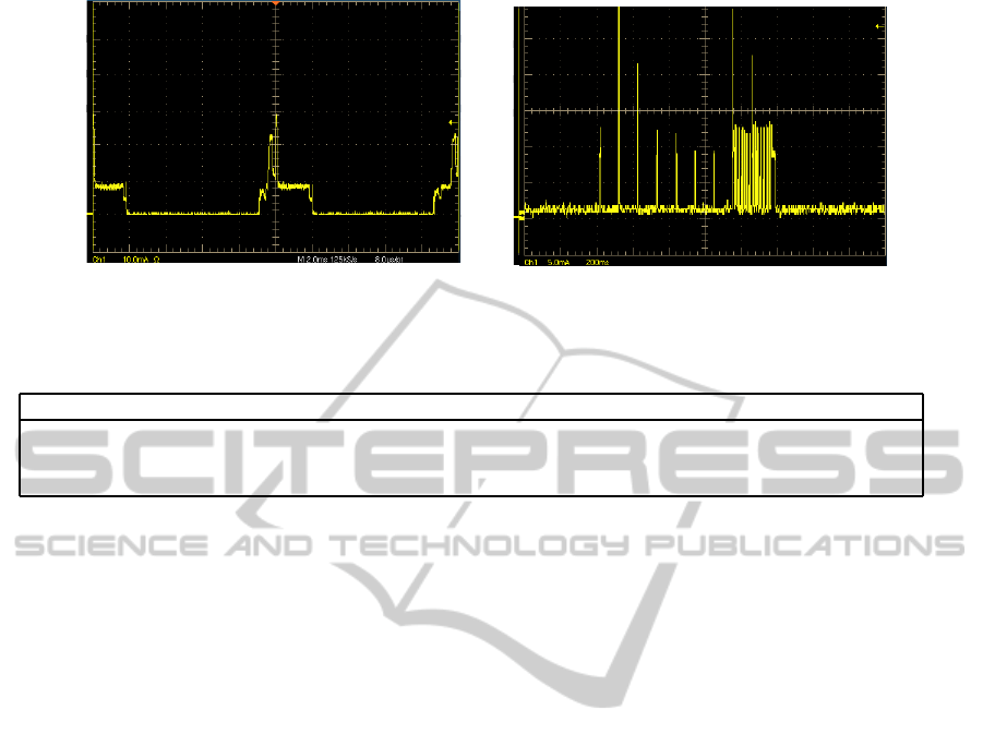
time (2msec/div)
current (10mA/div)
(a) initial one time advertisement mode
time (200msec/div)
current (5mA/div)
(b) periodic data transmission mode
Figure 12: Oscilloscope plot showing current measured using precision current probe for different modes of operation.
Table 4: Current consumption for different mode of operation.
Mode Peak current Average current On Time Energy from 3V @ 90%η
Sleep 1µA 1µA 899 sec 1.1 mJ
Data Transmission 30 mA 17 mA 1 sec 56.6 mJ
Initial Advertisement 30 mA 4.5 mA 180 sec 2700 mJ
• Testing within nationally and globally acceptable
ethical and legal frameworks for research on hu-
man participants
• Testing for potential scale-up on a large-scale
ACKNOWLEDGEMENTS
We acknowledge the Robert Bosch Center for Cyber
Physical Systems at the Indian Institute of Science for
funding support.
REFERENCES
Alf Helge, O. (2010). Bluetooth Low Energy: Wireless
Connectivity for Medical Monitoring. Journal of Di-
abetes Science and Technology, 4(2).
Artem, D., Steve, H., Stuart, T., and Joshua, S. (2013).
Power consumption analysis of Bluetooth Low En-
ergy, Zigbee, and ANT sensor nodes in cyclic sleep
scenario. IEEE International Wireless Symposium,
Beijing, China.
Bluetooth (2012). Health tempertute profile. https://
developer.bluetooth.org/TechnologyOverview/Pages/
HTP.aspx.
Boano, C., Lasagni, M., Romer, K., and Lange, T.
(2011). Accurate temperature measurements for
medical research using body sensor networks. In
Object/Component/Service-Oriented Real-Time Dis-
tributed Computing Workshops (ISORCW), 2011 14th
IEEE International Symposium on, pages 189–198.
Cantherm (2009). High precision ntc thermistors. http://
www.cantherm.com/products/thermistors/mf51e.html.
Chen, W., Dols, S., Oetomo, S. B., and Feijs, L. (2010).
Monitoring body temperature of newborn infants at
neonatal intensive care units using wearable sensors.
In Proceedings of the Fifth International Conference
on Body Area Networks, BodyNets ’10, pages 188–
194, New York, NY, USA. ACM.
Embrace (2012). A low cost infant warmer. http://
embraceglobal.org/.
Global Health (2010). Causes of neonatal and child mortal-
ity in india: a nationally representative mortality sur-
vey. The Lancet, 376(9755):1853 – 1860.
Gomez, C., Oller, J., and Paradells, J. (2012). Overview and
evaluation of bluetooth low energy: An emerging low-
power wireless technology. Sensors, 12(9):11734–
11753.
Hawley E, M.-D., Salvatore P, I., and Jonathan A, B. (2012).
Movement toward a novel activity monitoring device.
Sleep Breath, 16(3):913–917.
Isetta, V., Agustina, L., Lopez Bernal, E., Amat, M., Vila,
M., Valls, C., Navajas, D., and Farre, R. (2013). Cost-
Effectiveness of a New Internet-Based Monitoring
Tool for Neonatal Post-Discharge Home Care. Jour-
nel of Medical Internet Research, (15(2):e38).
iThermometer (2012). Bluetooth digital thermometer for
android devices. http://download.chinavasion.com/
download/CVXX-A140.pdf.
Kumar, V., Mohanty, S., and Kumar, A. (2008). Effect
of community-based behaviour change management
on neonatal mortality in shivgarh, uttar pradesh, in-
dia: a cluster-randomised controlled trial. The Lancet,
372(9644):1151 – 1162.
Kumar, V., Shearer, J. C., Kumar, A., and Darmstadt, G. L.
(2009). Neonatal hypothermia in low resource set-
tings: a review. Journal of Perinatology, 29:401–412.
Macfarlane, F. (2006). Paediatric anatomy, physiology and
the basics of paediatric anaesthesia.
Neurosynaptics (2002). http://www.neurosynaptic.com/.
LowPowerRemoteNeonatalTemperatureMonitoringDevice
37

Oestergaard, M. Z. and Inoue, M. e. a. (2011). Neonatal
mortality levels for 193 countries in 2009 with trends
since 1990: A systematic analysis of progress, projec-
tions, and priorities. PLoS Med, 8(8):e1001080.
Rutter, N. (2000). Clinical consequences of an immature
barrier. Seminars in Neonatology, 5(4):281 – 287.
Scavacini, A. S. A.-l., Miyoshi, M. H., Kopelman, B. I., and
Peres, C. A. d. A. A. (2007). Chest Expansion for As-
sessing Tidal Volume in Premature Newborn Infants
on Ventilators. Jornal de Pediatria, 83:329 – 334.
Stratasys (2013). High-quality, precise, multi-
material prototypes in a compact system.
http://www.stratasys.com/3d-printers/design-series/
precision/objet260-connex.
Susan, B., Debra, D., and Lori A, L. (2001). Neonatal Ther-
mal Care, Part II: Microbial Growth Under Tempera-
ture Probe Covers. Journal Neonatal Network: The
Journal of Neonatal Nursing, 20:19–23.
TI (2008). 2.4ghz inverted f- antenna. http://www.ti.com/
lit/an/swru120b/swru120b.pdf.
WHO (1993). Thermal Control of the Newborn: a Practical
Guide. Maternal and Safe Motherhood Programme.
WHO (2012). Newborn deaths decrease but account for
higher share of global child deaths.
WHO, UNICEF, and UN (2012). Levels and Trends in
Child Mortality Report.
BIODEVICES2014-InternationalConferenceonBiomedicalElectronicsandDevices
38
