Simulated Framework for the Development and Evaluation of
Redundant Robotic Systems
Ioannis Iossifidis
Computer Science Insitute, Ruhr West University of Applied Sciences, 45470 M
¨
ulheim an der Ruhr, Germany
Keywords:
Simulated Environment, Redundant Manipulator, Closed Form Solution, Kinematics.
Abstract:
In the current work we present a simulated environment for the development and evaluation of multi redundant
open chain manipulators. The framework is implemented in Matlab and provides solutions for the kinematics
and dynamics of an arbitrary open chain manipulator. For a anthropomorphic trunk-shoulder-arm configura-
tion with in total nine degree of freedoms, a closed form solution of the inverse kinematics problem is derived.
The attractor dynamics approach to motion generation was evaluated within this framework and the results are
verified on the real anthropomorphic robotic assistant Cora.
1 INTRODUCTION
Focusing on the movement of arcticulated robots as
part of autonomous acting robotic system, reaching
and grasping are still demanding tasks with increasing
complexity with respect to it’s generalization prop-
erties. The performance depends on the underlying
kinematical structure, the solution space of the invers
kinematical mapping and the trajectory generating ap-
proach. Since both, the invers kinematics and the tra-
jectory generation, depends on the underlying kine-
matical structure the manipulator has to be designed
carefully. The design process again should linked and
evaluated regarding the solution space of the invers
kinematical mapping and the proposed motion plan-
ning scheme until the overall system convergences
to a desired state. Although implementation on real
hardware is of mandatory importance for the proof of
concepts, the operational overhead is a limiting factor
for the development, optimization and assessment of
robotic systems and models. Simulation is a means to
to overcome those limitations.
We developed a framework consisting of an math-
ematical description of the kinematics and dynamics
of an arbitrary open chain manipulator and a simula-
tor programmed in Matlab, implementing the inverse
kinematics, simulating and visualizing it’s motion. In
the current implementation we propose a human like
kinematical structure with a multi redundant arm and
additional degree of freedoms in the shoulder and the
body, (for further discussion see (Hollerbach, 1984))
(Iossifidis et al., 2003)). The source code of the sim-
ulator is freely available on www.cstlab.net.
In the following we first describe the structure
of the trunk-arm-system represented by it’s forward
kinematics. Second we sketch the closed form solu-
tion for the whole system describing in detail how the
null space motion can be utilized to avoid obstacles or
joint limits. And in the last section the implementa-
tions of the simulator and some experimental results
are described.
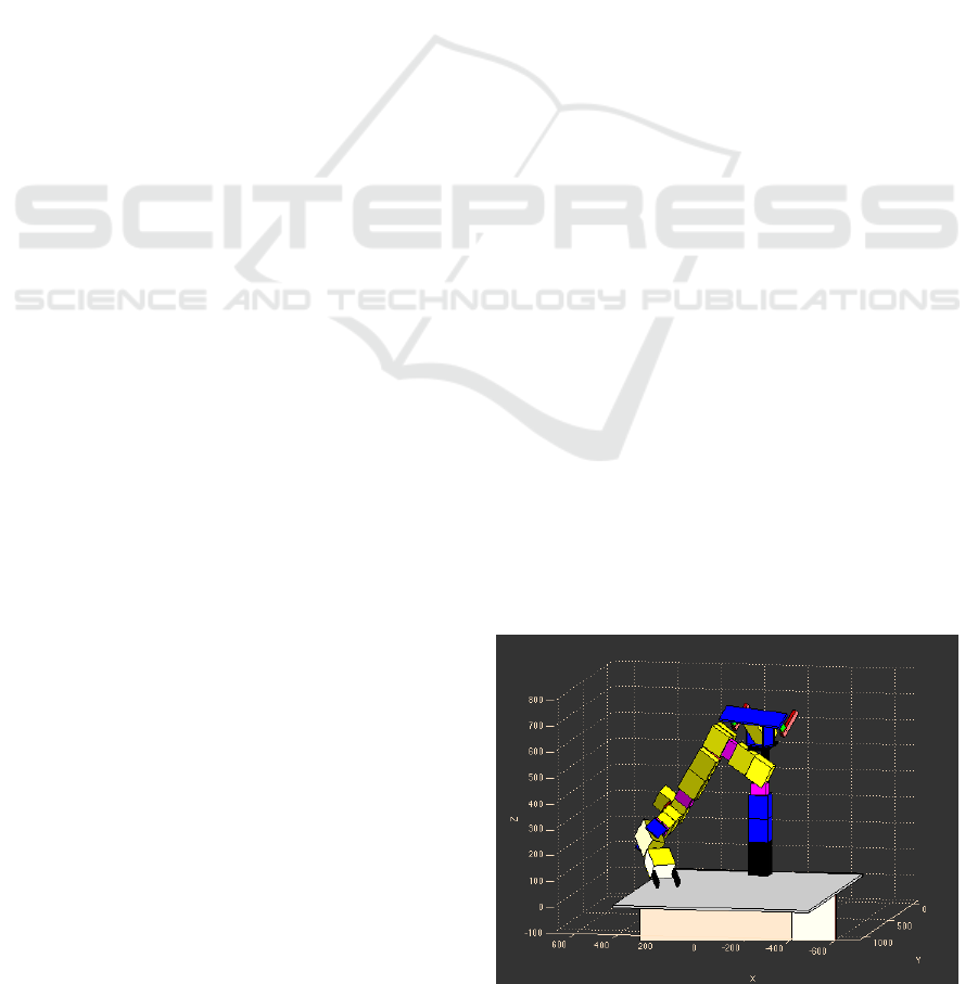
Figure 1: The MRobot-Simulator implements a robotic sys-
tem consisting of an nine degree of freedom manipulator
and a two degree of freedom sensor head.
55
Iossifidis I..
Simulated Framework for the Development and Evaluation of Redundant Robotic Systems.
DOI: 10.5220/0004802900550060
In Proceedings of the 4th International Conference on Pervasive and Embedded Computing and Communication Systems (PECCS-2014), pages 55-60
ISBN: 978-989-758-000-0
Copyright
c
2014 SCITEPRESS (Science and Technology Publications, Lda.)

2 OPEN CHAIN MANIPULATOR
2.1 Initial Configuration
The sketched structure models (in correspondence to
humans) a one degree of freedom trunk, a one degree
of freedom shoulder elevation/depression with an at-
tached seven degree of freedom arm. The arm consist-
ing of a rotating trunk, spherical shoulder and wrist
joints, and an elbow joint, for a total of nine degrees
of freedom. The reference configuration is show in
Figure 2.
x
y
T
θ
4
q
4
θ
6
q
6
θ
8
q
8
θ
3
q
3
θ
5
q
5
θ
7
q
7
θ
9
q
9
l
0
l
1
l
2
l
3
l
4
l
5
l
6
l
7
l
8
Base Shoulder Elbow Hand
EEF
z
q
1
S
θ
1
q
2
θ
2
Figure 2: A total of eight revolute joints are ordered along
the effector to simulate a human arm with trunk, shoulder,
elbow and wrist.
The manipulator is composed of a series of roll
and pitch joints. The combination of a roll-pitch-roll-
joint is functionally equivalent to a spherical three
DoF joint like the human shoulder or wrist. Similar
to the example above, the twists are determined as
ω
1
= ω
4
= ω
6
= ω
8
=
0
0
1
, ω
3
= ω
5
= ω
7
= ω
9
=
0
1
0
.
and
ω
2
=
0
1
0
Support points can be chosen as
q
i
=
0
∑
i−1
k=1
l
k
0
for i = 1,4,6,8,
and
q
i
=
0
∑
i−1
k=1
l
k
l
0
for i = 2,3,5,7,9.
This yields the twist coordinates
ξ
1
=
0
0
0
0
0
1
, ξ
4
=
l
1
+ l
2
0
0
0
0
1
, ξ
6
=
l
1
+ l
2
+ l
3
+ l
4
0
0
0
0
1
,
ξ
8
=
l
1
+ l
2
+ l
3
+ l
4
+ l
5
+ l
6
0
0
0
0
1
, ξ
2,3,5,7,9
=
l
0
0
0
0
0
1
.
The transformation between the base and end-effector
coordinate frames in reference configuration is
g
st
(0) =
I
0
∑
9
i=1
l
i
l
0
0 1
.
2.2 Forward Kinematics
The forward kinematics is calculated as the product of
exponential. On the basis of the simple ways of repre-
senting and calculating rigid transformations (for de-
tailed description see (Murray et al., 1994)), we can
move on to describe the transformation to the end ef-
fector of an open chain manipulator, that is, a chain
of n joints. For each joint, we define a joint twist ξ
i
that models the motion of the subsequent part of the
robot.
Let g
st
(0) be the transformation between the base
frame S of the manipulator and the end effector, or
tool frame T in the reference configuration, that is,
when all joint angles
1
θ
1
,...,θ
n
are set to zero.
Now we want to know what happens to the end ef-
fector after we apply a rigid transformation by moving
a joint. Starting at the base, we get to the end effector
via g
st
(0), which we then move by applying the rigid
transformation e
b
ξ
i
θ
i
. Combining these two transfor-
mation in the right order, we get
g
st
(θ) = e
b
ξ
i
θ
i
g
st
(0).
Here g
st
(θ) maps the center of the base frame to the
position of the end effector in the new configuration
with θ
i
6= 0. Thinking the other way round, it re-
turns the S-coordinates of a point that we specify in
T -coordinates. So if we specify “0”, we refer to the
position of the end effector in the frame T centered at
that point. Applying g
st
(θ) returns the coordinates of
that point in frame S, centered at the base. Thus, we
can think of g
st
(θ) as enabling us to specify a point
in a moving frame T , and get back its position in the
motionless frame S.
To do the same for a configuration in which sev-
eral joints have moved, i.e. θ
i
6= 0 for more than one i,
we just have to apply the appropriate transformation
1
By abusive convention, we refer to the amount of trans-
lation θ
k
of a prismatic joint k as angle, too, in order to
prevent cluttering up our language.
PECCS2014-InternationalConferenceonPervasiveandEmbeddedComputingandCommunicationSystems
56
q
u
α Elbow Redundancy Angle
q
f
q
m
q
h
q
g
q
ee f
R
q
w
β Trunk Redundancy Angle
b
x
B
b
z
B
b
y
B
z
sh
y
sh
x
sh
q
sh
γ Shoulder Redundancy Angle
Figure 3: The figure depicts the kinematical structure and the associated coordinate systems of an multi redundant nine degree
of freedom arm. α denotes the elbow angle, β denotes the trunk angle and γ the shoulder angle.
in the right order. Conceptually speaking, we start at
the end effector and go up the joints along the manip-
ulator till we reach the base, moving each joint by the
appropriate angle θ
i
on the way. This yields
g
st
(θ) = e
b
ξ
1
θ
1
···e
b
ξ
n
θ
n
g
st
(0) (1)
as the coordinate transformation from T to S in con-
figuration θ = (θ
1
,...,θ
n
).
Equation (1) is called the product of exponentials
formula for the manipulator forward kinematics.
3 CLOSED FORM SOLUTION
The analytic solution for the inverse kinematics for
an 9 DoF open chain manipulator will be descripted
in current section.
For the solution of the overall system we assume
that the shoulder is positioned due to the boundary
condition determined by the object to be manipulated,
like turning shoulder towards the object to extend it’s
workspace (distances to objects greater the the length
of the arm) or to position the shoulder to an orienta-
tion that is orthogonal to the target direction (optimal
grasping position). The shoulder elevation/depression
is utilized to satisfy additional constraints, like the
avoidance of undesired configurations.
Given the shoulder position, which is determined
by the trunk angle and the shoulder angle, the inverse
kinematic mapping of the seven degree of freedom
has to be derived with respect to shoulder coordinate
system.
In the following we derive first the inverse kine-
matics of the seven degree of freedom, exploiting it’s
geometric properties, and describe how the null space
motion can be utilized to satisfy constraints like ob-
stacle avoidance and joint limits.
3.1 Inverse Kinematics
Based on the work of (Kreutz-Delgado et al., 1990)
and (Hollerbach, 1984)) the inverse kinematics
problem for the nine degrees of freedom manipulator
is solved in closed form. In the following derivation
we denote the trunk angle with β and the shoulder an-
gle angle with γ (correspond to θ
1
and θ
2
in the initial
configuration in figure 2). We assume that the end ef-
fector position and hand orientation is determined by
the object to be grasped and that the trunk angle β and
shoulder angle γ will be choosen due to the boundary
conditions and costraints of the given task. First we
transform the given end effector position to the shoul-
der coordinate system by:
q
0
ee f
= T
S
sh
q
ee f
with
T
S
sh
=
1 0 0 0
0 1 0 −(l
2
+ l
1
)
0 0 1 −l
0
0 0 0 1
cos(−θ
1
) − sin(−θ
1
) 0 0
sin(−θ
1
) cos(−θ
1
) 0 0
0 0 1 0
0 0 0 1
cos(−θ
2
) 0 sin(−θ
2
) 0
0 1 0 0
−sin(−θ
2
) 0 cos(−θ
2
) 0
0 0 0 1
beeing the homogeneous transformation.
Given the hand orientation θ
h
(elevation) and φ
h
(azimuth) and the tool point q
0
ee f
, the vector q
h
from
the wrist to the hand reference tool-point (Fig. 3) is
determined as
q
h
= R
z
(φ
h
)R
y
(θ
h
)
b
e
y
l
h
(2)
where R
x
, R
z
denote rotation matrices around the z-
and y-axes and l
h
denotes the segment length.
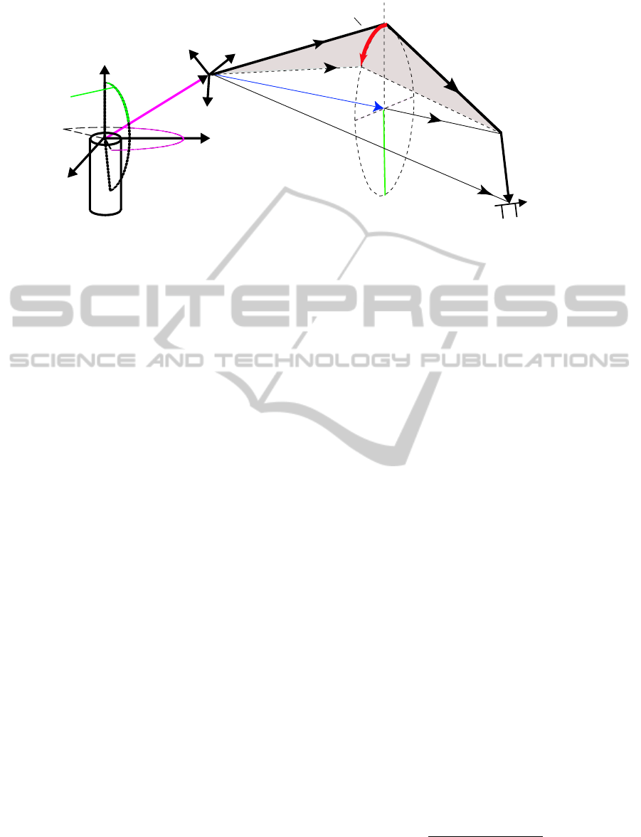
The redundant degree of freedom is defined by the
redundancy circle, the center
q
m
=
|
q
u
|
2
−
q
f
2
+
|
q
w
|
2
2
|
q
w
|
2
q
w
(3)
of which lies on a ray pointing from the shoulder to
the wrist joint. The spatial position of the elbow lies
SimulatedFrameworkfortheDevelopmentandEvaluationofRedundantRoboticSystems
57
κ
α
q
h
q
f
µ
ψ
φ
κ
R
h
r
δ
δ
o
b
x
B
b
y
B
b
z
B
κ
obs
forearm
obstacle
upper arm
elbow position
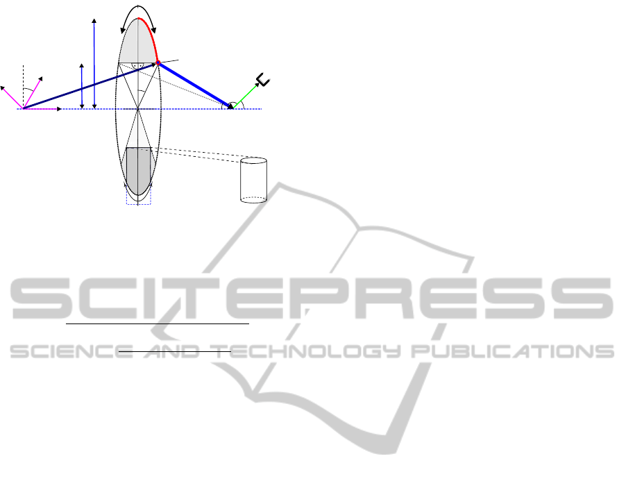
Figure 4: Geometrical construction to avoid joint configu-
rations at the wrist and an obstacle reaching into the redun-
dancy circle defines a to-be-avoided angular segment of that
circle.
on this circle of radius r, with
r =
v
u
u
t
|
q
u
|
2
−
|
q
u
|
2
−
q
f
2
+
|
q
w
|
2
2
|
q
w
|
!
2
(4)
Expressing the wrist vector, q
w
, through two angles,
φ
w
and θ
w
, the elbow position can be written as
q
u
= (R
x
(φ
w
)R
z
(θ
w
)R
x
(α) ˆe
y
)r + q
m
(5)
where R
x
and R
z
are rotation matrices around the x-
and the z-axis and the redundancy angle α character-
izes the position of the elbow on the redundancy circle
(Fig. 3). If α is specified, all limb vectors are known.
A straightforward solution of the inverse kinematics
determines the joint angles. θ
3
,θ
4
,θ
5
,θ
6
,θ
7
,θ
8
,θ
9
(for more detail see (Iossifidis, 2013)).
3.1.1 Constraints for the Redundancy Circle
The redundancy angle α spans all redundant arm con-
figurations consistent with the same tool position and
orientation. The rate of change of the redundancy an-
gle generates self-motion, which can be used to ac-
commodate the two additional constraints of obsta-
cle avoidance for the upper arm and joint limits at the
wrist. To do that, we must compute which sectors
on the redundancy circle are forbidden by these con-
straints.
Any obstacle o
i
, that reaches up to the elbow, de-
fines a to-be-avoided segment on the redundancy cir-
cle centered on κ
i
and with an angular range of σ
i
(see
Fig. 4) Transforming limitations of joint angle range
into constraints on the redundancy circle is more com-
plicated. The most important joint angle limitation
concerns the wrist, where the lower arm and the hand
are spatially aligned. The angle µ between the hand
q
h
and the forearm q
f
must be larger than π/2, which
is true as long as
−(π − µ) ≤ θ
8
≤ π − µ. (6)
Fig. 4 illustrates that this can be used to compute the
corresponding allowed sector on the redundancy cir-
cle.
To do that, define a coordinate system the z
0
-axis
of which is aligned with the shoulder-wrist-axis of the
robot arm. If φ
w
and θ
w
describe the azimuth and ele-
vation of the wrist, then the transformed hand vector,
q
0
h
is:
q
0
h
= R
−θ
w
y
R
−φ
w
z
q
h
(7)
After the transformation, the redundancy circle lies
in a plane parallel to the x
0
y
0
-plane, so that we may
project q
0
h
onto that plane to obtain:
κ = arctan(q
y
h
0
,q
x
h
0
) (8)
as the center of the prohibited sector of the redun-
dancy circle. The angular extent of the prohibited re-
gion κ ± δ follows from equation 6:
δ = arccos(h
r
/r) (9)
where h
r
, ψ, c and φ are auxiliary quantities, which
can be derived from figure 4:
h
r
= c · tan(ψ) (10)
c = |q
w
| − |q
m
| (11)
ψ = π − (µ + φ) (12)
φ = arccos
q
z
h
0
/
q
h
0
. (13)
The obstacle induced prohibited region on the re-
dundancy cycle is calculated analogous, with κ
o
as
the center of the prohibited region and δ
o
as it’s ex-
tend (figure 4).
4 IMPLEMENTATION AND
RESULTS
The goal was to develop a simulator for an arbitrary
open chain manipulator. In sections 2 and 3 we in-
troduced the necessary formularism to calculate the
kinematic and dynamic terms. With the help of these
formulas it was possible to develop a simulator evalu-
ating the proposed solutions and visualize the motion
of the robotic system. The software architecture of
this simulator shall be described briefly in this section
and in the following we evaluate the attractor dynam-
ics approach to motion generation performing target
acquisition and obstacle avoidance.
PECCS2014-InternationalConferenceonPervasiveandEmbeddedComputingandCommunicationSystems
58
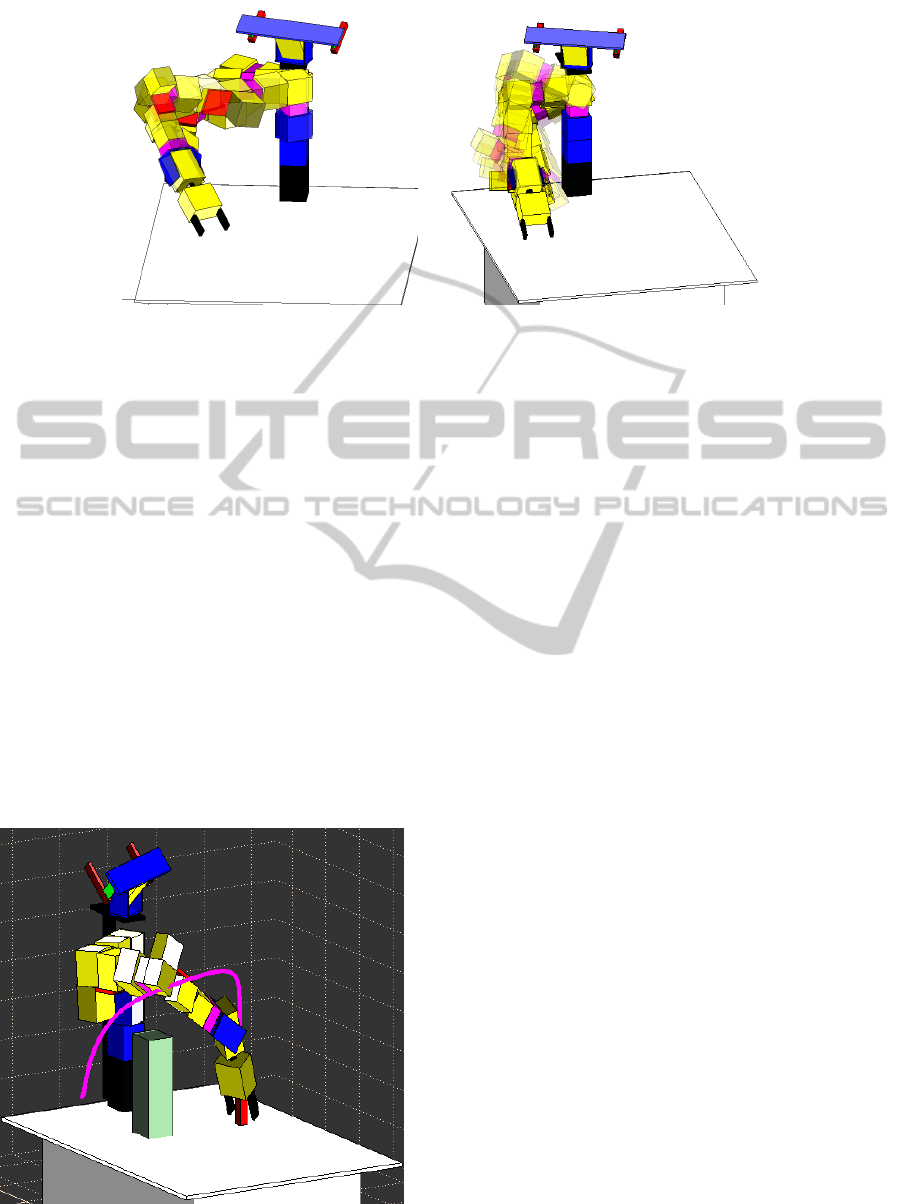
(A) (B)
Figure 6: (A) shows how the shoulder angle varies between −30
◦
and 30
◦
. (B) The trunk angle varies from −30
◦
to 30
◦
. In
both cases the position and orientation of the endeffector remains invariant.
4.1 MRobot
The MRobot-Simulator is an Matlab implementation
of the presented nine degree of freedom manipulator.
The simulator includes the constraints handling (see
figure 5) as well as the shoulder and trunk motion (see
figure 6). All parameters can be changed through the
gui and the simulated arm motion will be updated im-
mediately.
At this we would like to note that for a shoul-
der angle of 30 the presented manipulator correspond
with the kinematical structure of one of the manipu-
lators of the mobile robot Justin ((Borst et al., 2009))
and that the presented closed form solution solves it’s
inverse kinematics.
Figure 5: The robotic system utilizes redundancy to avoid
obstacles.
4.2 EXPERIMENTS
In order to prove the functionality of the simulator we
have implemented the attractor dynamics approach
to motion generation (Iossifidis and Sch
¨
oner, 2006)
in order to realize goal directed trajectories and to
evaluate the obstacles avoidance properties of the ap-
proach. Target and obstacle related parameters were
picked at random.
The experimental results generated by the simula-
tor for multiple target-obstacle-configuration led to a
systematical classification of the performance of the
approach and pointed out it’s limitations. In addi-
tion we could identify which part in the closed form
solution of the inverse kinematics lead to undesired
configuration changes. The detailed discussion of this
experimental results is beyond this paper and will be
part of future publications.
Figure 7 illustrate one experimental run. After
the motion is initiated the evolving trajectory point
directly in the direction of the target (A). Once the
end effector approaches the obstacle, repelling forces
pushes the end effector away from the initial direc-
tion (deforming trajectory – magenta line) and the end
effector follows a trajectory over the obstacle (B-C).
As soon as the distance between the end effector and
obstacle becomes larger, and the end effector leaves
the obstacles area of influence, the trajectory relaxes
again to the target direction. Finally the end effector
reaches the target (D).
5 CONCLUSIONS
A simulated framework consisting of an mathemat-
ical description of the kinematics and dynamics for
arbitrary open chain manipulator and a simulator pro-
SimulatedFrameworkfortheDevelopmentandEvaluationofRedundantRoboticSystems
59
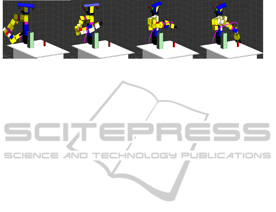
(A) (B) (C) (D)
Figure 7: he figure shows the MRobot accomplishing a reaching task while avoiding obstacle. The magenta line depicts the
trajectory of the end effector.
grammed in Matlab was introduced. Part of the
framework is the implementation of a closed form so-
lution for the inverse kinematical mapping for multi
redundant manipulators (up to nine DoF). The frame-
work provide ground truth data of all parameters for
further analysis, an intuitive interface and a visual-
ization front end for the whole robotic system. The
software is freely available under cstlab.net.
REFERENCES
Borst, C., Wimbock, T., and Schmidt, F. (2009).
Rollin’Justin-Mobile platform with variable base. In
Robotics and Automation, 2009. ICRA’09. IEEE
International Conference on, pages 1597—-1598.
IEEE.
Hollerbach, J. (1984). Optimum kinematic design for a
seven degree of freedom manipulator. In 2nd Int.
Symp. Robotics Research, pages 215 –222.
Iossifidis, I. (2013). Motion Constraint Satisfaction by
Means of Closed Form Solution for Redundant Robot
Arms. In Proc. IEEE/RSJ International Conference
on Robotics and Biomimetics (RoBio2013).
Iossifidis, I. and Sch
¨
oner, G. (2006). Dynamical Systems
Approach for the Autonomous Avoidance of Obsta-
cles and Joint-limits for an Redundant Robot Arm. In
2006 IEEE/RSJ International Conference on Intelli-
gent Robots and Systems, pages 580–585. IEEE.
Iossifidis, I., Theis, C., Grote, C., Faubel, C., and Sch
¨
oner,
G. (2003). Anthropomorphism as a pervasive de-
sign concept for a robotic assistant. In Proceed-
ings 2003 IEEE/RSJ International Conference on
Intelligent Robots and Systems (IROS 2003) (Cat.
No.03CH37453), volume 4, pages 3465–3472. IEEE.
Kreutz-Delgado, K., Long, M., and Seraji, H. (1990). Kine-
matic analysis of 7 DOF anthropomorphic arms. In
Robotics and Automation, 1990. Proceedings., 1990
IEEE International Conference on, pages 824 – 830.
Murray, R., Li, Z., and Sastry, S. (1994). A mathematical
introduction to robotic manipulation. CRC Press.
PECCS2014-InternationalConferenceonPervasiveandEmbeddedComputingandCommunicationSystems
60
