
Test Bench for Analysis of Harmful Vibrations Induced
to Wheelchair Users
A. Ababou, N. Ababou, T. Morsi and L. Boukhechem
Laboratory of Instrumentation, University of Science and Technology Houari Boumediene,
BP32 El Alia BabEzzouar 16111 Algiers, Algeria
Keywords: Harmful Vibrations, Whole-Body Vibration, Wheelchair, MEMS, Accelerometers, Signal Processing.
Abstract: In this paper, a test bench for analysis of harmful vibrations that can be transmitted by manual wheelchair ti
its user is presented. The vibration generating device developed in the laboratory and sensors positioning
are described. Vibration measurements were carried out using four tri-axis MEMS accelerometers and a
position sensor. Experimental data were noisy, so they were first filtered before acceleration amplitude can
be assessed using two methods that we propose: a so-called ‘cyclogram method’ and ‘DFT principal peak
signal magnitude’ on the other hand. The second one is faster and results showed that the prototype
developed in the laboratory can provide harmful vibrations in 2-10Hz frequency range and can be used to
check the vibration transmissibility of wheelchair.
1 INTRODUCTION
According to the World Health Organization more
than one billion people in the world live with some
form of disability, of whom nearly 200 million
experience considerable difficulties in functioning.
In the years ahead, disability will be an even greater
concern because its prevalence is on the rise (World
Health Org. and World Bank, 2011) The results of
studies conducted by Van Sickle et al. and Wolf et
al. (Van Sickle et al., 2001; Wolf et al., 2005) have
shown that a wheelchair user is subjected to
vibrations that often exceed the limits specified by
the International Standard Organization ISO
2631-
1standard. Directive 2002/44/EC of the European
Parliament and of the Council dated June 25 2002
lays down minimum requirements for the protection
of workers from the risks arising from vibrations.
Manufacturers of machines and employers should
make an adjustment regarding risks related to
exposure to whole-body vibration. The directive
lays down the exposure action to 0.5m/s² and the
exposure limit value to 1.15m/s² (European
Commission Directive, 2002). These limits have
been set to indicate the level of vibration that results
in productivity loss of workers and it seems to be
analogous to wheelchair users by reducing their
activity levels (Pearlman et al., 2013). Whole-body
vibrations (WBV), acting via the buttocks, the back
and the feet of a sitting person may cause chronic
spinal cord injuries (Johanning, 2011). Rather than
measuring vibration exposure on a road, Maeda et
al. (Maeda et al., 2003) used a vibrating table to
vibrate on subjects sitting in a wheelchair. Subjects
were subjected to vertical vibration inducing more
discomfort, and reported the neck as being the place
where localized pain resulting from vibrations.
Other studies have been focused on how the
selection of the cushion and backrest can affect
WBV absorption by the body and examined the
influence of different surfaces on the sidewalk
vibration exposure of wheelchair users (Garcia-
Mendez et al., 2012; Qiu and Griffin; 2012; Wolf et
al., 2007).
Frequencies associated with the effects of WBV
on health, activities and comforts vary between
0.5Hz and 100Hz (ISO, 1997). According to ISO
2631-1 standard on human vibration, individuals in
a seated position are at risk of injury due to whole-
body vibrations when exposed for long periods of
time. Exposure to vibrations in the range of 4-10Hz
frequency may cause pain in the chest and abdomen.
Back pain occurs frequently with vibrations in the
frequency range of 8-12Hz, and vibration in the
frequency in 10-20Hz range can cause headache,
eyestrain, and irritation in the intestines (Kittusamy
and Buchholz, 2004; Bovenzi, 2010; Johanning,
147
Ababou A., Ababou N., Morsi T. and Boukhechem L..
Test Bench for Analysis of Harmful Vibrations Induced to Wheelchair Users .
DOI: 10.5220/0004806001470153
In Proceedings of the International Conference on Biomedical Electronics and Devices (BIODEVICES-2014), pages 147-153
ISBN: 978-989-758-013-0
Copyright
c
2014 SCITEPRESS (Science and Technology Publications, Lda.)
2011).
Human exposure to vibration may be measured
using accelerometers. However, weighting filters are
required to correlate the physical vibration
measurements to the human’s response to vibration.
ISO 2631 standard describes suitable weighting
filters, but does not explain how to implement them
for digitally recorded acceleration data. Rimell and
Mansfield described in their paper the
implementation of the weighting filters used in three
different standards as digital IIR (Infinite Impulse
Response) filters and provided all the necessary
formulae to directly calculate the filter coefficients
for any sampling frequency (Rimell and Mansfield,
2007).
In this paper a test bench developed in our
laboratory is presented. It can produce harmful
vibrations that can be transmitted by a wheelchair to
its user on one hand, and can give quantitative
assessment of vibration magnitude on the other
hand. Vertical as well as rocking strokes can be
generated at frequencies in 2-10Hz range. As a first
step, the characterization of the vibrations generated
by the device is investigated.
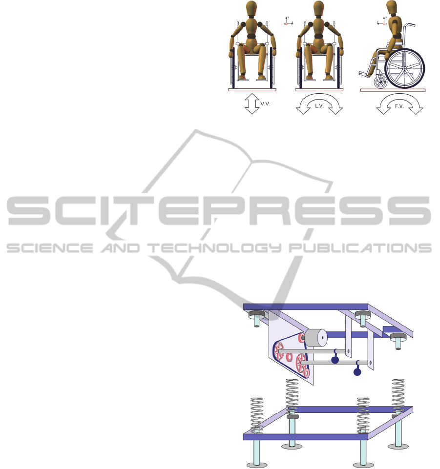
2 BASIC VIBRATIONS
When a manual wheelchair user moves outdoor, one
can consider that he can be submitted to
multidirectional vibrations that can be a composition
of three basic vibrations, i.e. vertical (along z-axis),
lateral (along x-axis) and fore-and-aft (along y-axis)
vibrations as shown schematically in Fig.1. The
vertical vibration noted V.V. is generally induced by
the quality of the tires and the road conditions
(Pearlman et al., 2013). The lateral vibration noted
L.V. corresponding to a roll, may be due to veiled
wheels, to the passage of a single wheel above a
small drop, or uneven road surfaces (Cooper et al.,
2011). The fore-and-aft vibration noted F.V.
corresponding to a pitch, may be caused by
corrugation of the road, by crossing small steps, a
door sill or by certain sort of floor tiles or for all-
terrain wheelchairs riding (Burton et al., 2010;
Rispin and Wee, 2013).
Vertical, lateral and fore-and-aft vibrations in
this work are generated by a device that can be
configured so that only vertical vibration or rocking
vibration is selected. The magnitude of vibration
can be quantified either by its amplitude (mm), its
velocity (m/s) or its acceleration (m/s²).
Figure 1: Basic vibrations that can be induced on a manual
wheelchair: vertical vibration V.V, lateral vibration L.V
and fore-and-aft vibration F.V.
3 EXPERIMENTAL
3.1 Experimental Set-up
The test bench schematic shown in Fig. 2 consists of
vibrating table which comprises three blocks: a base
anchored to the ground and supporting four coil
springs, a movable plate having guide tubes and a
vibration generator controlled by a variable-speed
drive.
Figure 2: Schematic of the vibrating table.
The base consists of a framework based on four feet
on the ground and secured with 4 coil springs.
Theses springs allow the upper part of the test bench
to vibrate freely along the three axes so as to
produce vertical as well as lateral and fore-and-aft
movements. The vibration plate is composed of a
rectangular frame surface with ties for supporting a
motor with its guiding device, two cogwheels, two
pinions and a tensioner pulley. Each cogwheel shaft
sustains an eccentric weight which generates
BIODEVICES2014-InternationalConferenceonBiomedicalElectronicsandDevices
148
mechanical vibration at each rotation.
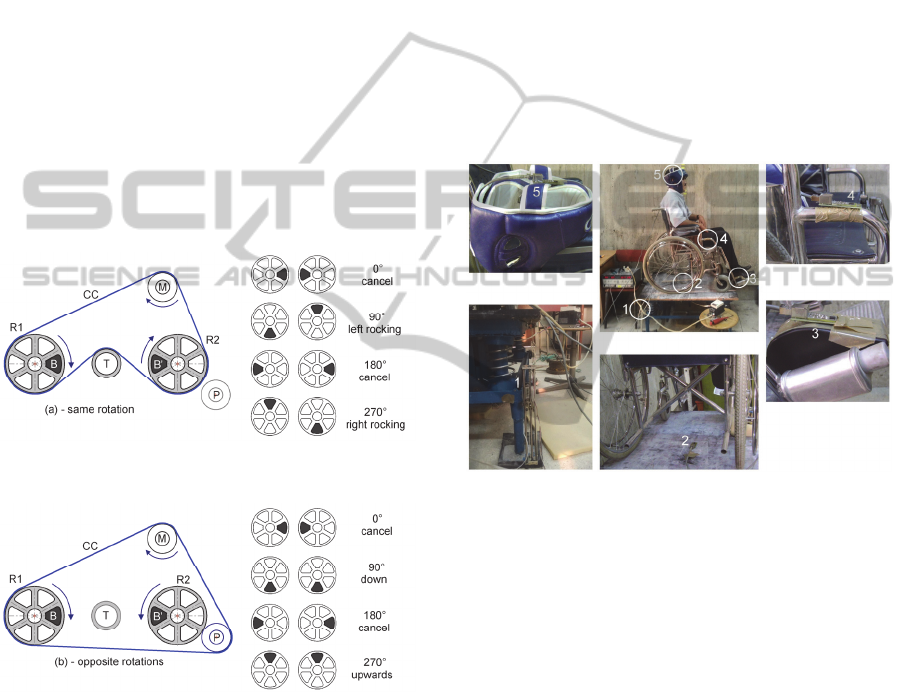
Figure 3 shows the details of the transmission of
the movement using a toothed belt (CC). In the case
(a), the motor M drives the two wheels R1 and R2 in
the same direction, the belt tension is provided by
the tensioner T. Resulting movement of eccentric
weights B and B' causes rocking motion left to right
and right to left. In the case (b), the pinion P is used
to invert the rotation of the toothed wheel R2
relative to that of the wheel R1. The resulting
movement of the eccentric weights B and B'
generates a vertical vibration.
Rotational speed of the induction motor M was
controlled by a Siemens Micromaster variable-speed
drive (VSD).
Rotational speed of the motor evolution versus
the VSD excitation frequency has been investigated
using a DT-2269 digital stroboscope from Digital
Instruments and a linear behaviour of rotational
speed has been observed.
Figure 3: Patterns of the transmission system of the
movement - (a) generation of rocking vibration due to the
resulting force-couple : left rocking (90°) and right
rocking (270°) - (b) generation of vertical vibration
resulting from centrifugal force action up (270°) and down
(90°) on the two eccentric weights. Positions of B and B’
when rotated by 90°, 180°, 270° and 360°.
3.2 Sensors Positioning
For vibration amplitude measurements four
MMA7260Q tri-axis MEMS accelerometers with
analog outputs have been used. A linear
potentiometric position sensor has also been placed
under the vibrating table to measure the amplitude
(in mm) of the generated mechanical vibrations.
Accelerometers static and dynamical calibrations
were performed before measurements have been
carried out. Experimental data of the position sensor
calibration curve have been adjusted by a line whose
slope was equal to 1.93V/mm with a correlation
coefficient equal to 0.99997.
The sensors were arranged as shown in Fig. 4.
The four accelerometers were placed in a horizontal
plane so that the x-axis pointed to the left of the
subject, the y axis and the z-axis pointed to forward
and downward respectively. Their sensitivity was set
to 200mV/g and they were also equipped with
analog anti-aliasing filters with cutoff frequency
equal to 40Hz.
Figure 4: Sensors positioning on the vibrating table, the
manual wheelchair and the user: (1) position sensor; (2)
Acc-T; (3) Acc-F; (4) Acc-W; (5) Acc-H.
Acc-T, Acc-F, Acc-W and Acc-H are respectively
the accelerometers placed on the vibrating table,
footrest, frame of the manual wheelchair and on the
head (vertex) of seated subject. The accelerometer
Acc-T placed on the table gives the same signal as
the vibration provided by the vibration generator.
Accelerometers Acc-W and Acc-F respectively
placed on the wheelchair frame and footrest are used
to compare the signal supplied by the vibration
generator and the vibration transmitted to two
extreme points of the wheelchair in order to quantify
the vibration magnitude transmitted by the
wheelchair. The last accelerometer placed on the
vertex of the subject sitting in the wheelchair
provide information on the quality of vibration
transmitted to the point of the subject is seated
furthest both the wheelchair system for generating
vibration. The level of vibration transmitted to the
subject's head can then be assessed.
TestBenchforAnalysisofHarmfulVibrationsInducedtoWheelchairUsers
149
3.3 Acquisition and Data Processing
For acquisition and processing the analog data ssued
from the four tri-axis accelerometers and position
sensor, a 12-bit acquisition DAQCard-6062E from
National Instruments has been used and data
sampled at 1kHz. Measurements have been carried
out for duration equal to 10s on a healthy male
subject 1.75m tall and 75kg weight seated in a
manual wheelchair for eight different values of
vibration frequency: 2, 3.2, 4.4, 5.6, 8, 9, 10 and
10.6Hz. The selected vibration duration can be
considered as sufficiently short to avoid health
problems for the subject (ISO, 1997). Fig. 5 shows
an example of signal acceleration output along z-
axis at a vibration frequency equal to 4.4Hz
provided by the accelerometer Acc-W located on
wheelchair frame after analog filtering. For more
convenience, raw acceleration data are displayed
only for duration equal to 5s. The signal remains
noisy after analog anti-aliasing filtering.
Figure 5: Example of z-axis signal issued from
accelerometer (Acc-W) located on wheelchair frame.
The DFT of the vibration signal expressed in m/s²
and depicted in Fig. 5 is presented in Fig.6. One can
notice the presence of one principal peak at 4.4Hz
and several harmonics at higher frequencies. The
first principal peak has been observed for all the
eight vibration frequencies applied to the
wheelchair.
Because of lack in the DFT response of other
peaks with appreciable magnitude compared to the
first one, we did not consider in this work the
weighting filters usually used in literature to
correlate the physical vibration measurements to the
human’s response to vibration and described in
ISO2631 standard. A digital band-pass filter has
been applied to the vibration signal of Fig.5.
Selected low and high cutoff frequencies for the
filtered signal presented in Fig.7 have been set to
f
cl
= 3Hz and f
ch
= 7Hz respectively.
Figure 6: DFT response in semi-log plot of the raw
acceleration signal presented in Fig. 4.
Figure 7: Acceleration signal depicted in Figure 5 after
band-pass filtering (fcl= 3Hz ; fch= 7Hz).
4 RESULTS AND DISCUSSION
In order to assess quantitatively the vibrations
magnitude along x, y and z axis measured by all
accelerometric sensors, the frequency of the
variable-speed driver has been varied from 10Hz to
50Hz. These values correspond to vibrations
delivered by the test bench to the wheelchair-user
system with a frequency varying in 2-10.6Hz range.
The graphs shown in Fig. 8 depict for a column
from top to bottom an example of measured then
filtered 10.6Hz vibration magnitude at the vibrating
table (T), the wheelchair frame (WF), footrest (F)
and the user head (H) along one axis(x, y or z).
When considering a raw, from left to right, the
measured accelerations correspond respectively to
vertical acceleration along z-axis, fore-and-aft
acceleration along y-axis and lateral acceleration
along x-axis at one of the four selected locations.
BIODEVICES2014-InternationalConferenceonBiomedicalElectronicsandDevices
150
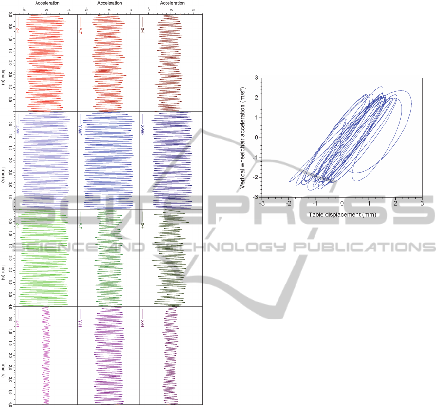
Figure 8: Example of vibration signals measured by the
four accelerometers. In this example, vibration frequency
f=10.6Hz.
Thus, for a given vibration frequency generated by
the test bench, a comparison between different
points of measure along the same axis (x, y or z) can
be achieved by considering one column (among
three columns) and between different accelerations
patterns at one location (vibrating table, wheelchair
frame, wheelchair footrest or user head) is obtained
by considering one raw (among four raws). One can
note on these graphs that acceleration amplitude
varies with both time and location. To assess the
amplitude of vibration measured by the
accelerometers for different values of vibration
frequency, we have represented cyclograms
corresponding to the evolution of the acceleration
value (in one direction and for one accelerometric
sensor) versus the position of vibrating table plate of
the test bench. The cyclogram associated with
vertical wheelchair acceleration at f=4.4Hz (See
Fig.5 and Fig.7) is presented in Fig. 9.
Figure 9: Example of cyclogram corresponding to
acceleration value versus table displacement.
From the different cyclograms obtained from
experimental measures, acceleration amplitudes
along z-axis (vertical vibration), y-axis (fore and aft
vibration) and x-axis (lateral vibration) have been
quantitatively assessed for the eight values of
vibration frequency delivered by the test bench at
the four selected locations.
Furthermore, for each temporal acceleration
signal, we considered the principal peak magnitude
of the DFT signal. Fig.10 shows the variation of the
acceleration amplitude obtained from cyclograms as
a function of the DFT magnitude, expressed in
arbitrary units due to scaling factor. It is worth
noticing that a correlation between these two
variables seems to be present. Experimental data
were fitted by a straight line with a slope found to be
equal to 4.83.10
-3
. Hence, acceleration amplitude
can easily be deduced from DFT principal peak
height with a relative uncertainty less than 20%.
According to ISO2631-1 and European
Commission Directive (European Commission
Directive, 2002) the vibration should not exceed the
weighted acceleration a
w
=0.8m/s² in the case of
long-term exposure and a daily exposure time of 8h.
Furthermore, ISO2631-1 recommends weighting the
frequencies of the measured vibration according to
the possible deleterious effect associated with each
frequency.
Frequency weightings are required for three
orthogonal directions (x -, y – and z -axes) at the
interfaces between the body and the vibration.
TestBenchforAnalysisofHarmfulVibrationsInducedtoWheelchairUsers
151
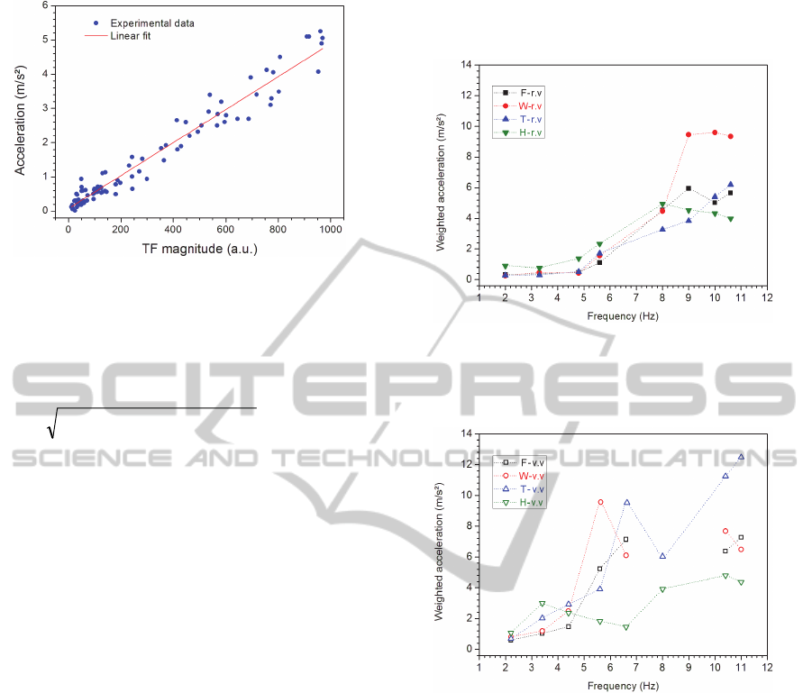
Figure 10: variation of acceleration amplitude obtained
from cyclograms versus DFT signal magnitude.
The weighted acceleration in the case of whole-body
vibration is expressed (Bovenzi, 2005) by the
relation (1)
2
z
2
y
2
xw
)a()a4.1()a4.1(a
(1)
Once the values of a
x
, a
y
and a
z
has been obtained
from cyclograms, the weighted acceleration has
been calculated for the vibrating table, the
wheelchair frame and footrest, and the user head for
the eight different values of frequency vibration.
Deducing acceleration amplitudes directly from
DFT vibration magnitude for a given frequency is
another method which is simpler than considering
the cyclogram method.
We used the DFT magnitude method and
equation (1) to obtain weighted accelerations for
different vibration frequencies. The results presented
in Fig. 11 are associated with the test bench in
rocking vibration configuration while those depicted
in Fig.12 are associated with the test bench in
vertical vibration configuration. Weighted
acceleration values are expressed in m/s².
For vibration frequencies lower than 5Hz, the
obtained weighted acceleration values are
sufficiently low to consider the vibration not
harmful when the test bench is in rocking vibration
configuration. When vibration frequency exceeds
5Hz, the weighted acceleration value associated with
the wheelchair increases drastically, reaching almost
10m/s² for f > 8Hz. In the second case, except for f
= 2Hz, all other values of weighted acceleration
show that the test bench generates harmful
vibrations for vibration frequencies effects.These
frequencies are principally inducing back pain and
backbone disorders. Hence, the device developed in
the laboratory can be used to check the quality of the
wheelchairs that are marketed in developing
countries from the vibration transmissibility point of
view.
Figure 11: weighted acceleration versus vibration
frequency with test bench rocking vibration (r.v)
configuration. F: wheelchair footrest; W:wheelchair
frame; T: vibrating table; H: user head.
Figure 12: weighted acceleration versus vibration
frequency with test bench in vertical vibration (v.v)
configuration. F: wheelchair footrest; W:wheelchair
frame; T: vibrating table; H: user head.
5 CONCLUSIONS
A test bench for analysis of harmful vibrations that
can be potentially induced to a manual wheelchair
user has been developed in the laboratory.
Vibrations generated by the device were measured
using MEMS accelerometers and a position sensor.
The experimental signals were noisy and were first
filtered before being processed. Two methods have
been used to assess vibration magnitude, the
cyclogram method and DFT principal peak
magnitude method. The obtained weighted
acceleration values showed that the device
developed in the laboratory provides harmful
BIODEVICES2014-InternationalConferenceonBiomedicalElectronicsandDevices
152

vibrations and can be used to check the vibration
transmissibility of manual wheelchair.
In further work, this test bench will be used to
investigate the vibration effect and the wheelchair
design (rigid frame, foldable, wheel camber) as well
as tires and cushion damping effects on the harmful
vibration magnitude.
ACKNOWLEDGEMENTS
This work was supported in part by MESRS
ministry under grant J0200220100018. The authors
wish to thank Mr H. Zerouali for his participation in
the prototype developing.
REFERENCES
Bovenzi, M., 2005, ‘Health effects of mechanical
vibration’, G. Ital. Med. Lav. Erg., vol.27, n°1, pp.58-
64.
Bovenzi, M., 2010, ‘A longitudinal study of low back pain
and daily vibration exposure in professional drivers’,
Industrial Health, vol.48, pp.584-595.
Burton, M., Fuss, F. K., and Subic A., 2010, ‘Sports
wheelchair technologies’. Sports Technology vol.3,
n°3, pp. 154–167.
Cooper, R. A., Teodorski, E. E., Sporner M. L., and
Collins, D. M., 2011, ‘Manual wheelchair propulsion
over cross-sloped surfaces: a literature review’.
Assistive Technology, vol.23, pp.42–51.
European Commission Directive ECD 2002/44/EC of the
European Parliament and of the Council, 2002. ‘on
the minimum health and safety requirements regarding
exposure of workers to the risks arising from physical
agents (vibration) ’, Official Journal of the European
Communities vol. L177, pp.13-19.
Garcia-Mendez, Y., Pearlman, J. L., Cooper, R. A.,
Boninger, M. L., 2012, ‘Dynamic stiffness and
transmissibility of commercially available wheelchair
cushions using a laboratory test method’, Journal of
Rehabilitation Research & Development, vol.49, n°1,
pp. 7-22.
International Organization for Standardization, 1997,
‘Mechanical vibration and shock Evaluation of human
exposure to whole-body vibration Part 1: General
requirements (ISO 2631-1)’.
Johanning, E., 2011, ‘Diagnosis of whole-body vibration
related health problems in occupational medicine’,
Journal of Low Frequency Noise, Vibration and
Active Control, vol.30, n°3, pp.207-220.
Kittusamy, N. K. and Buchholz, B., 2004, ‘Whole-body
vibration and postural stress among operators of
construction equipment: a literature review’, Journal
of Safety Research, vol.35, n°3, pp.255-261.
Maeda, S., Futatsuka, M., Yonesaki, J., Ikeda, M., 2003,
‘Relationship between questionnaire qurvey results of
vibration complaints of wheelchair users and vibration
transmissibility of manual wheelchair’, Environmental
Health and Preventative Medicine, vol.8, pp. 82-89.
Pearlman, J., Cooper, R., Duvall, J., Livingston, R., 2013,
‘Pedestrian pathway characteristics and their
implications on wheelchair users’, Assistive
Technology, vol.25, pp.230-239.
Rimell, A. N. and Mansfield, N. J., 2007, ‘Design of
digital filters for frequency weightings required for
risk assessments of workers exposed to vibration’,
Industrial Health, vol.45, n°4, pp.512–519.
Rispin, K., and Wee, J., 2013, ‘A paired outcomes study
comparing two pediatric wheelchairs for low resource
settings; the Regency pediatric wheelchair and a
similarly sized wheelchair made in Kenya’. Assistive
Technology, DOI: 10.1080/10400435. 2013.83784
Qiu, Y., Griffin, M. J., 2012, ‘Biodynamic response of the
seated human body to single-axis and dual-axis
vibration: effect of backrest and non-linearity’,
Industrial Health, vol.50, n°1, pp.37–51.
VanSickle, D. P., Cooper, R. A., Boninger, M. L.,
DiGiovine, C. P., 2001. ‘Analysis of vibrations
induced during wheelchair propulsion’, Journal of
Rehabilitation Research & Development, vol.38, n°4,
pp. 409-421.
Wolf, E. J., Pearlman, J., Cooper, R. A., Fitzgerald, S. G.,
Kelleher, A., Collins, D. M., Boninger, M. L., Cooper,
R., 2005, ‘Vibration exposure of individuals using
wheelchairs over sidewalk surfaces’. Disability &
Rehabilitation, vol.27, n°23, pp. 1443-1449.
Wolf, E., Cooper, R. A., Pearlman, J., Fitzgerald, S. G.,
Kelleher, A., 2007, ‘Longitudinal assessment of
vibrations during manual and power wheelchair
driving over select sidewalk surfaces’, Journal of
Rehabilitation Research & Development, vol.44, n°4,
pp. 573-580.
World Health Organization, World Bank, 2011, World
report on disability. Available from
http://whqlibdoc.who.int/hq/2011/WHO_NMH_VIP_
11.01_eng.pdf.
TestBenchforAnalysisofHarmfulVibrationsInducedtoWheelchairUsers
153
