
A Deployment-oriented Development Process based on Context
Variability Modeling
Ka Chun Anthony Lee
1,2
, Maria-Teresa Segarra
1
and Stephane Guelec
2
1
Department of Computer Science, Telecom Bretagne, Brest, France
2
Orange Labs, Lannion, France
Keywords:
Distributed Deployment, Context-awareness, Variability Modeling.
Abstract:
With the explosion of the usage and capabilities of mobile devices, software deployment is getting more
and more complicated. In order to tackle the difficulty of achieving adaptive and distributed deployment, a
deployment-oriented development process is presented in this paper. While existing deployment methodolo-
gies are lack of variability concern, the approach takes advantage of a variability model in order to define
context variability at design time. With the usage of a transformation utility and a deployment system, deploy-
ment constraints that identified by software architects can be enforced from design time to deployment time.
It facilitates the deployment tasks for software architects by automating the interpretation between abstract
definitions and operation detail. The approach will be presented with a use case scenario and some model
example in order to point out the research orientation and position.
1 INTRODUCTION
Software deployment is an important task to select the
appropriate services and architectures of an applica-
tion that executes on a set of target execution contexts.
In order to decide the appropriate services and archi-
tectures, several aspects such as cost, performance,
reliability and security could be considered. More-
over, it is essential to ensure that once the application
is deployed, it will be executed as expected. However,
deployment consideration could be a time consuming
and error prone task for software architects especially
when their application can be executed in thousands
of possible ways.
With the explosion of the usage and capabilities of
mobile devices, software deployment is getting more
and more complicated. Indeed, an application archi-
tecture can be deployed in several different types of
devices. Software architects have to consider deploy-
ing several architecture variants on several variants of
execution contexts.
Analyzing deployments in this situation of many
to many combination is time consuming and error
prone by using traditional deployment methodologies
(Dearie, 2007). Deployment plans may either be es-
tablished manually or generated by some predicate
that requires long period of learning. It increases the
difficulty for finding the best deployment solution for
different execution contexts. Moreover, there is a lack
of technical method for enforcing deployment con-
straints identified by software architects at application
design time.
In order to solve these problems, we propose
an approach for managing and verifying deployment
constraints. The approach is based on a deployment-
oriented development process that is described in sec-
tion 2. Model and constraint definitions are explained
in section 3 with a use case scenario. Related work
are analyzed in section 4. Future work are mentioned
in the conclusion.
2 THE DEPLOYMENT
ORIENTED DEVELOPMENT
PROCESS
Model-driven engineering (MDE) is one promising
development methodology in the software engineer-
ing domain. It focuses on creating blueprints (mod-
els) of different software aspects such as architecture,
functionality and execution process in order to facili-
tate system compatibility, simplify development pro-
cess and team communication (Schmidt, 2006). We
take advantage of MDE in our deployment-oriented
approach for describing possible execution contexts
454
Lee K., Segarra M. and Guelec S..
A Deployment-oriented Development Process based on Context Variability Modeling.
DOI: 10.5220/0004806304540459
In Proceedings of the 2nd International Conference on Model-Driven Engineering and Software Development (MODELSWARD-2014), pages 454-459
ISBN: 978-989-758-007-9
Copyright
c
2014 SCITEPRESS (Science and Technology Publications, Lda.)
of an application and compute the most suitable de-
ployment plan. In order to address the lacks of cur-
rent deployment solutions, our approach has 4 main
purposes:
• To establish a set of model definitions for describ-
ing context variability at high abstraction level
in order to facilitate analysis of deployment con-
straints
• To automate interpretation and verification de-
ployment constraints.
• To enforce deployment constraints from design
time to deployment time.
• To reuse context analysis for multiple applications
on the same platform.
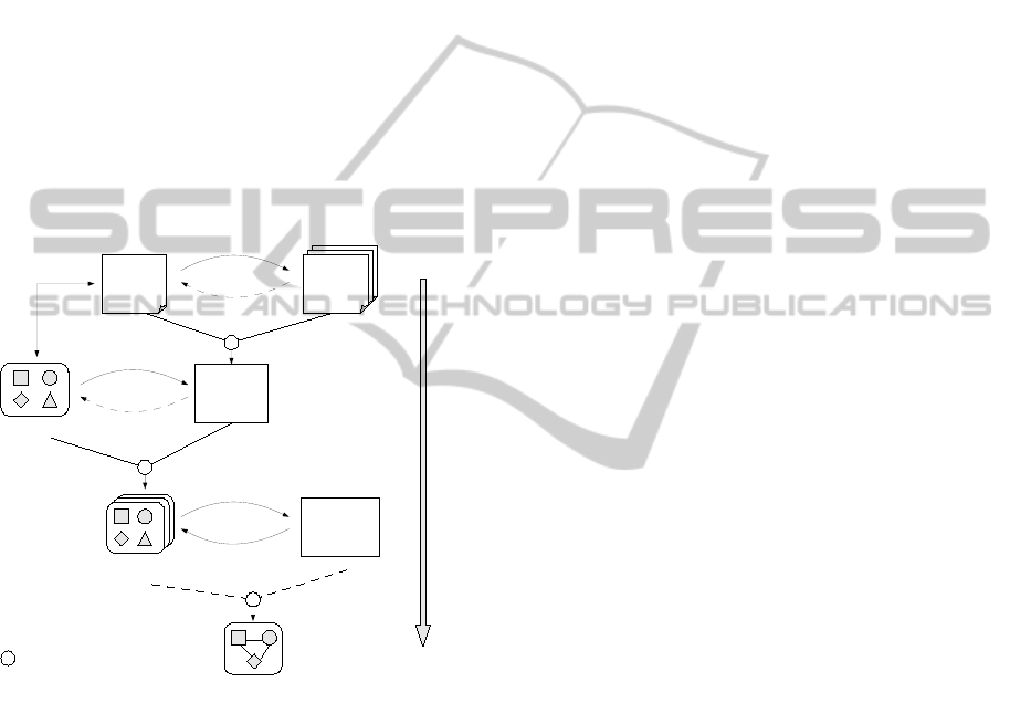
An overview of the development process is de-
scribed in Figure 1.
Application
Elements
An
Application
Variability
Model
Context
Variability
Models
Deployment
Constraints
Possible variants for
different contexts
Indications
Influences
Embed
Constrain
Deployment
system and
Repository
Stored
Manages
D
e
p
l
o
y
m
e
n
t
-
o
r
i
e
n
t
e
d
d
e
v
e
l
o
p
m
e
n
t
p
r
o
c
e
s
s
A particular configuration and a deployment
of an application for an identified context
- Interpretation
- Generation
- Combination
- Packaging
Provided Utility
- Deployment
Design time
Deployment time
Associated
Figure 1: Deployment-oriented development process.
In our process, both variants of an application and
variants of execution context are modeled at design
time by software architects. As shown on the top of
the figure, required execution contexts of application
variants are indicated as models. The deployment of
the application in terms of architecture, functionality
and location is influenced by these contexts.
Context variability and application variability
models and their relations are automatically inter-
preted by a utility to generate system verifiable de-
ployment constraints. These constraints can be com-
bined with related application elements. The result
is a packaged application with different deployment
possibilities according to the constraints. It is then
stored in a repository and ready to be deployed.
A deployment system that is capable to perform
the MAPE (Monitoring, Analyzing, Planning and Ex-
ecuting) (IBM Corp., 2004) can then be used in the
execution environment to compute the most suitable
deployment plan for a particular execution context
based on the identified constraints.
The approach can help software architects to spec-
ify context-aware deployment easier by saving devel-
opment time and cost. Several technologies and mod-
eling approaches can be considered in the approach
and they are described in next section.
3 MODELING VARIABILITY
In order to realize the development process, sev-
eral existing technologies have been used. However,
particular definitions and assumptions are applied to
them for deployment purpose. They are analyzed in
this section with a use case scenario.
Let us consider a project in a telecommunication
operator where an execution platform is targeted to
provide different services to its users by allowing var-
ious applications running on it. These applications are
implemented by different third party software houses.
While marketing people and system engineers from
the telecom service provider are responsible for de-
veloping the execution platform, software architects
and developers from different software houses are re-
sponsible for their own application design and devel-
opment in order to deploy them on the platform.
3.1 Assumptions on Modeling
Variability
As describing variability is the focusing point in the
approach, Feature Model (FM) (Kang et al., 1990) is
used for defining both application variants and con-
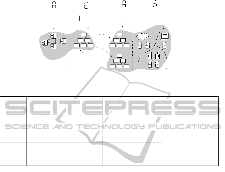
text variants. It is shown in the middle of Figure 2.
A FM is a tree like model aims at defining common
and variable features of an application. Component
technology is also used to help on separating an ap-
plication implementation into different service units
that can be configured. As depicted in Figure 2, plat-
form engineers and marketing people define possible
execution contexts as Feature Models. On the other
hand, software architects identify application variants
that guide developers to implement the application.
Then they can identify the deployment constraints of
the application by following the specification of our
proposed methodology.
Nevertheless, there are several assumptions that
have to be mentioned in the approach:
ADeployment-orientedDevelopmentProcessbasedonContextVariabilityModeling
455
Targets
.
.
.
Different execution contexts
such as hardware architectures
Constraints
Software architects
System/Platform engineers
Software developers
Marketing people
Component
implementations
Analysis in Feature Models
Develop
Identify
Define
Figure 2: Roles in the use case.
Table 1: Multilevel description of context.
Context
variability
level
Context information Connection information
Defined by
0
Location abstraction
(physical or logical spaces)
Connection type
abstraction
Software architects
and Platform providers
1
Types of device
(Hardware nodes)
2
Ranges of attributes of a device type -
3
Actual environments
(Instances of device)
Available connections of
each device and location
Retrieved by sensors in
actual environments
• Software architecture variability is defined at the
component level and should be associated with
deployment feature models.
• A service of an application is implemented as one
component and represented as a feature
• Connections and services will be considered at
component level only
Based on these assumptions, definitions of models
and constraints are established as described in the next
section.
3.2 Context FM and Constraints
While common and variable functionalities are de-
scribed as features in the application FM, variable
contexts are described as Types in context FM. A type
is considered as an abstraction of a category of con-
text. Because not all contexts are relevant to deploy-
ment purposes and some of them are difficult to be
verified, contexts are separated into several levels and
will be structured into multiple feature models. The
definitions are shown in Table 1. A use case scenario
will be described in the next section.
Context information can be structured into 4 dif-
ferent levels, from level 0 to level 3. Level 0 to level
2 contain context information that can be defined by
software architects and platform providers at design
time. Level 3 context information is the actual envi-
ronment that can be retrieved by sensors but cannot
be defined precisely at design time. In the develop-
ment process, variants of location should be defined
first. A location should be defined as an abstraction
of a physical or a logical space that is interesting for
deployment purposes. One or several device(s) could
exist in a location. Then, variants of device in each
location should be categorized into Types in a FM.
Software architects should consider the influence of
each Type on the deployment decision in order to de-
fine them. After that, level 2 information can be de-
fined if attribute level variability is important for the
deployment. However, only static attributes can be
defined such as versions of software platform, CPU
speed and storage size. It is because modeling dy-
namic attributes such as latency could become am-
biguous and they could change too frequently, which
make them irrelevant for deployment. Variants of
connection type should be defined for modeling con-
MODELSWARD2014-InternationalConferenceonModel-DrivenEngineeringandSoftwareDevelopment
456
nections between location abstractions and between
device types in one or multiple FMs.
At deployment time, connections between 2 de-
vices or 2 locations will be traced by a routing algo-
rithm. A device in an actual context can be matched
to a type in a location abstraction with different
ranges of attributes. Therefore, appropriate deploy-
ment plans can be found if they satisfy a combination
of required context variants.
Software architects can indicate several types of
constraints as shown in Table 2.
Table 2: Types of deployment constraints.
Within AFM Between
AFM and CFMs
Constraint
indications
- Co-located
- Separated
- Mandatory require
(if only one)
- Optional require
(if multiple)
- Require to exist or
Require to install
- Connection
requirement
Constraints can be defined within an Application
FM (AFM) or be defined in between an Application
FM and Context FMs (CFMs). Features of an applica-
tion can be constrained as Co-located or Separated in
a location. An application feature may have a Manda-
tory require on a context variant or multiple Optional
requires on multiple context variants. A require con-
straint could just require a variant to exist or require a
variant to be able to execute a feature.
Software architects can use these definitions to
indicate the deployment constraints at design time.
They can then be enforced by the utility until the de-
ployment time in order to compute appropriate de-
ployment plans.
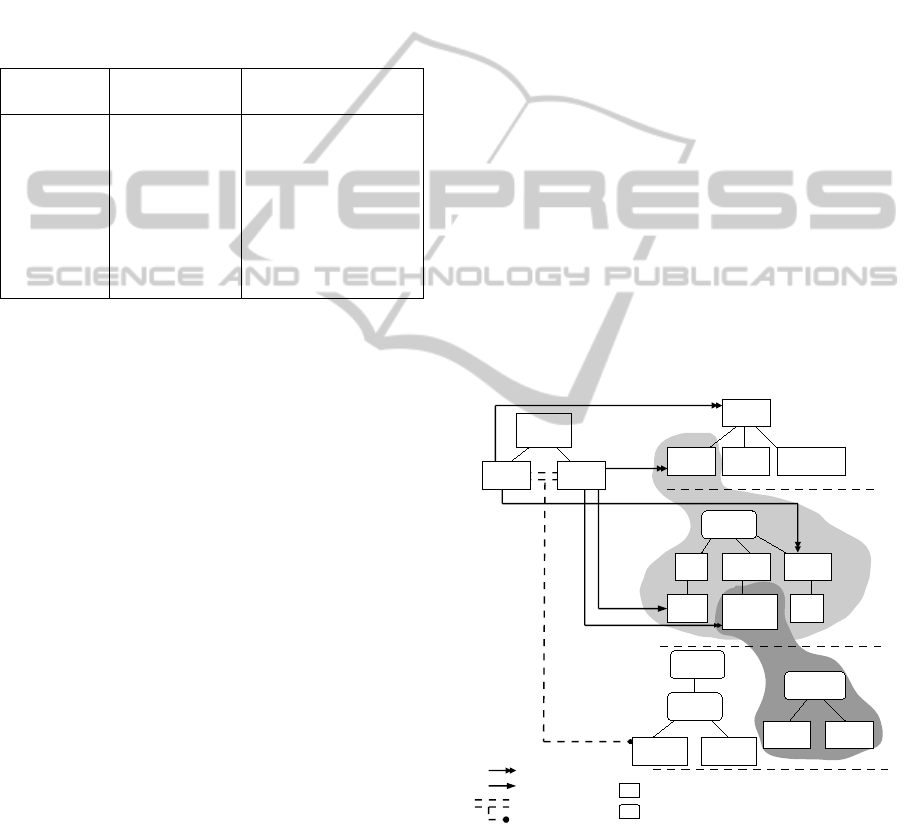
3.3 Model Examples
According to the definitions described in the previ-
ous section, model examples of the use case scenario
are shown in Figure 3. Let’s consider a very sim-
ple application called Energy Monitoring that can be
purchased from the execution platform of a telecom-
munication operator. It provides energy consumption
calculation and notification services. These 2 services
are the functionality variants of the application and
each service is implemented by a component. They
are described in the application FM called Display
and Control shown on the top left of the figure.
In order to require specific context in the platform,
context variants are defined from level 0 to level 2
on the right of the figure. Three location variants are
defined at level 0 FM which are Home, Cloud and
Mobile. They represent the customer home network,
cloud internet and customer mobile network respec-
tively. Device type variants are defined at level 1 ac-
cording to the needs of the telecommunication oper-
ator. As shown in the figure, 3 device type variants
could exist in the Home location. Manageable Equip-
ments (ME) are devices fabricated by the operator
such as an internet access gateway and a set-top-box.
The operator can gain full control of these devices.
MEEx are manageable equipments with execution ca-
pabilities. Equipments with profile services (ES) refer
to the devices that can be controlled via one or cer-
tain communication standards such as Universal Plug
and Play (UPnP) and Digital Living Network Alliance
(DLNA). Standard equipments (SE) means devices
that are not controllable by default. However, they can
be controlled by installing relevant application soft-
ware such as a PC, a tablet or a smartphone. Attribute
variants related to a device type or connections are
defined at level 2. For example, the CPU speed of a
gateway box can be lower than 2GHz or equal/greater
than 2GHz. Moreover, the bandwidth of a connec-
tion can be lower than 20Mbs or equal/greater than
20Mbs.
Location
Component
implementations
Home Cloud
Mobile
Device
ES MEEx
Sensor
Energy
Monitoring
Display
Control
< 2GHz
>= 2GHz
Connection
<20Mbs
>=20Mbs
Gateway
Box
PC
Level 0
Level 1
Level 2
SE
Require to install
Require to exist
Connection requirement
Legends
Application FM Context FM
Bandwidth
Variant
Variation point
CPU Speed
Figure 3: Constraint modeling between AFM and CFMs.
As shown in the figure, constraints can be defined
with variants but not variation points. However, loca-
tion is a specific variant point that represent a variant
of “any location” among to the defined variants. Ac-
cording to the definitions mentioned in section 3.2,
various constraints can be defined and some of them
are shown in the figure. For example, the Display ser-
ADeployment-orientedDevelopmentProcessbasedonContextVariabilityModeling
457

vice can be deployed and installed to any location.
If it has been deployed in Home location, a standard
equipment is required for installation as indicated by
a constraint. On another hand, the Control service
can only be deployed in Home location in order to
monitor the residential energy consumption of a user.
It has to be deployed on a gateway box regardless
it CPU speed or other attribute variants. It also re-
quires existent of sensor type devices in the home lo-
cation. Furthermore, a connection constraint is indi-
cated between the Control service and Display ser-
vice where the bandwidth has be to greater than or
equal to 20Mbs. The values of bandwidth here are
static according to the definition of the telecom ser-
vice provider. As the connection between the 2 ser-
vices could be a combination of several connections,
the routing algorithm will find out the lowest band-
width among them in order to verify the constraint.
According to our approach, these definitions will
be interpreted by a utility and verifiable data are gen-
erated as outputs. The data contain information such
as variants types and variants ranges that can be un-
derstand by a deployment system. The system can
find out matched information via context monitors in
different locations.
3.4 Prototype Implementation
In order to demonstrate the feasibility of the deploy-
ment methodology, two prototypes are planned to be
implemented for the development approach.
3.4.1 Deployment Modeling Prototype
This prototype is aimed at simulating the deploy-
ment modeling process that take advantage of Feature
Model for facilitating deployment tasks for software
architects. It should be able to let its users to cre-
ate feature models that describing application and ex-
ecution context variants. It should also allow to give
indications of deployment needs and constraints be-
tween services of an application and the possible ex-
ecution contexts such as hardware architectures. De-
ployment constraint files should be generated by the
prototype according to all defined deployment infor-
mation. These files are then can be combined with
related service components in order to be verified by
the Deployment middleware prototype at runtime.
3.4.2 Deployment Middleware Prototype
A first step deployment middleware prototype was
implemented by using JAVA and Service Component
Architecture (SCA) (OASIS, 2011) technologies. It
is aimed to simulate adaptive deployments accord-
ing to predefined deployment constraints about exe-
cution contexts. It is capable to install and activate
service components remotely thanks to the fraSCAti
(Seinturier et al., 2011) platform. The next step pro-
totype should be capable to deploy service compo-
nents into distributed locations according to the de-
ployment constraint files that generated by the de-
ployment modeling prototype. Due to the scope of
this paper and space limit, the implementation details
of the prototypes will not be mentioned.
There are different existing researches aim at ad-
dressing deployment problems and they are men-
tioned in the next section.
4 RELATED WORK
Existing deployment solutions can be roughly divided
into Model-Based approaches and Agent-based ap-
proaches. Model-based approaches such as OMG
D&C (OMG, 2006) aims to facilitate remote deploy-
ment and configuration in an environment with het-
erogeneous devices for component-based distributed
applications. OASIS SDD (OASIS, 2008) is a XML
based description model that aims at providing a stan-
dardized way to facilitate the management of deploy-
ment life-cycle. CDDLM (OGF, 2005) is a distributed
deployment framework presented by Global Grid Fo-
rum (GGD) that mainly targets applications that us-
ing Web Service (WS) technology. Although these
models provide detail definitions for handling deploy-
ment requirements, context variability and deploy-
ment constraint enforcement are not considered.
Agent based solution such as Nix (Dolstra et al.,
2004), is a package manager that treat software ap-
plications as packages for management tasks such
as update, deploy and system rollback. It provides
command line controls and a particular operation lan-
guage for managing and building packages. Smart-
Forg (Goldsack et al., 2009) is a deployment frame-
work that proposed by HP Lab for component-based
applications configuration, deployment, communica-
tion, discovery and lifecycle managements. Deploy-
Ware (Flissi et al., 2008) is a component-based de-
ployment framework that targets distributed and het-
erogeneous software systems. It aims to address the
issues of heterogeneity of software, network proto-
cols, and physical hosts. However, most of them lack
of deployment modeling facilities and require learn-
ing of control predicates which is time consuming.
There is lack of an automatic transformation between
definition at high abstraction level and execution at
operation level.
MODELSWARD2014-InternationalConferenceonModel-DrivenEngineeringandSoftwareDevelopment
458

Furthermore, several researches showed that Fea-
ture Model could be used to capture deployment con-
straints. In (Jansen and Brinkkemper, 2005), the au-
thors proposed an approach for binding FM and com-
ponent model to perform application deployments.
They identified deployment states such as source,
built, installed as requirement features for binding
with different component implementations. An other
approach concerning QoS requirements with Feature
Model was presented in (Wang et al., 2010). QoS re-
quirements details such as property types, compari-
son types are first model in ontology relations. Re-
quired QoS types are then used to bind with corre-
sponding application features in FM. A scenario of
financial trading system is analyzed. In (Fernandes
et al., 2011), the authors proposed a similar methodol-
ogy to develop context-aware applications but with a
higher level of abstraction to represent context in fea-
ture model. Multiple FMs are used to model different
variable contexts and each context feature is related
to a predicate expression. They have shown that the
feasibility of using FM to model different variability
other then application services.
5 CONCLUSIONS AND FUTURE
WORK
A deployment-oriented development process and an
use case scenario have been presented in this paper.
Although our approach is not the first research take
advantage of feature model for context modeling, it
aims at achieving adaptive and distributed deploy-
ments with context variability and constraint enforce-
ment considerations from design time to deployment
time that is not focused by other researches. How-
ever, several future works have to be continue in or-
der to optimize the solution. First, meta-model defini-
tions for defining each type of context have to be es-
tablished. Second, rules for transforming model def-
initions into verifiable constraints files have to be de-
fined. Moreover, completed prototypes have to be im-
plemented in order to demonstrate the approach. We
believe that the paper pointed out the research orien-
tation and positioned our research in the targeted do-
mains.
REFERENCES
Achilleos, A., Yang, K., and Georgalas, N. (2010). Context
modelling and a context-aware framework for perva-
sive service creation: A model-driven approach. Per-
vasive and Mobile Computing, 6:281296.
Dearie, A. (2007). Software deployment, past, present and
future. Future of Software Engineering, pages 269–
287.
Dey, A. K. (2001). Understanding and using context. Per-
sonal and Ubiquitous Computing, 5:4–7.
Dolstra, E., de Jonge, M., and Visser, E. (2004). Nix: A
safe and policy-free system for software deployment.
USENIX conference on System administration, pages
79–92.
Fernandes, P., Werner, C., and Teixeira, E. (2011). An ap-
proach for feature modeling of context-aware software
product line. Journal of Universal Computer Science,
17:807–829.
Flissi, A., Dubus, J., Dolet, N., and Merle, P. (2008). De-
ploying on the Grid with DeployWare. In Proceedings
of the 8th International Symposium on Cluster Com-
puting and the Grid (CCGRID’08), pages 177–184,
Lyon, France. IEEE. Rank (CORE) : A.
Goldsack, P., Guijarro, J., Loughran, S., Coles, A., Far-
rell, A., Lain, A., Murray, P., and Toft, P. (2009).
The smartfrog configuration management framework.
ACM SIGOPS Operating Systems Review, 43:16–25.
IBM (2004). The software deployment mystery solved a
customer guide.
IBM Corp. (2004). An architectural blueprint for auto-
nomic computing. IBM Corp., USA.
Jansen, S. and Brinkkemper, S. (2005). Modelling deploy-
ment using feature descriptions and state models for
component-based software product families. Compo-
nent Deployment, 3798:119–133.
Kang, K. C., Cohen, S. G., Hess, J. A., Novak, W. E.,
and Peterson, A. S. (1990). Feature-oriented domain
analysis (foda) feasibility study. Technical report,
Carnegie-Mellon University Software Engineering In-
stitute.
OASIS (2008). Solution deployment descriptor specifica-
tion.
OASIS (2011). Service component architecture assembly
specification.
OGF (2005). Cddlm configuration description language
specification.
OMG (2006). Deployment and configuration of
component-based distributed applications specifica-
tion.
Schmidt, D. C. (2006). Model-driven engineering. IEEE
Computer, 39(2):25–31.
Seinturier, L., Merle, P., Fournier, D., Schiavoni, V., De-
marey, C., Dolet, N., and Petitprez, N. (2011). Frascati
online user guideline.
Wang, T., Si, Y., Xuan, X., Wang, X., Yang, X., Li, S.,
and Kavs, A. J. (2010). A qos ontology cooperated
with feature models for non-functional requirements
elicitation. In Proceedings of the Second Asia-Pacific
Symposium on Internetware.
ADeployment-orientedDevelopmentProcessbasedonContextVariabilityModeling
459
