
Tracking by Shape with Deforming Prediction for Non-rigid Objects
Kenji Nishida
1
, Takumi Kobayashi
1
and Jun Fujiki
2
1
National Institute of Advanced Industrial Science and Technology (AIST), Tsukuba, Japan
2
Department of Applied Mathematics, Fukuoka University, Fukuoka, Japan
Keywords:
Tracking, Deforming Objects, Shape Prediction, Motion Feature.
Abstract:
A novel algorithm for tracking by shape with deforming prediction is proposed. The algorithm is based on the
similarity of the predicted and actual object shape. Second order approximation for feature point movement by
Taylor expansion is adopted for shape prediction, and the similarity is measured by using chamfer matching
of the predicted and the actual shape. Chamfer matching is also used to detect the feature point movements
to predict the object deformation. The proposed algorithm is applied to the tracking of a skier and showed a
good tracking and shape prediction performance.
1 INTRODUCTION
Visual object tracking is used in a wide range of com-
puter vision applications, such as surveillance sys-
tems, intelligent transport systems, and human action
analysis. The primary function of an object tracking
algorithm is to find the regions in an image that con-
tain movements. Therefore, in the first approach, pro-
posed by Koller, a background subtraction algorithm
was employed (Koller et al. 1994). However, in this
approach, the performance of the background estima-
tion was degraded when the movement of the objects
was small, and it also required an appropriate illumi-
nation condition.
The second approach comprises a group of
feature-based tracking algorithms (Beymer et al.
1997; Coifman et al. 1998; Kim and Malik, 2003).
Salient features such as corner features are individu-
ally extracted and tracked are grouped as belonging to
the corresponding object. It can be robust to illumi-
nation change. However, the precision of the object
location and dimension is affected by the difficulties
that arise in feature grouping. Another feature-based
approach is called the mean-shift algorithm (Comani-
ciu and Meer, 2002; Comaniciu et al. 2000), in which
the local features (such as color histograms) of pixels
belonging to the object are followed. The mean-shift
approach allows robust and high-speed object track-
ing, if a local feature that successfully discriminates
the object from the background exists. However, it is
difficult to discriminate objects that are close to each
other and are similar in color, or to adopt this method
for gray-scale images.
The third approach can be classified as a detect-
and-track approach. Avidan redefined the track-
ing problem as that of classifying (or discriminating
between) the objects and the background (Avidan,
2002). In this approach, features are extracted from
both the objects and the background; then, a classifier
is trained to classify (discriminate between) the ob-
ject and the background. Grabner trained a classifier
to discriminate an image patch with an object in the
correct position and image patches with objects in the
incorrect position (Grabner, 2006), and thereby, the
position of the object could be estimated more pre-
cisely. While this approach allows stable and robust
object tracking, a large number of computations are
necessary. The approach of Collins and Mahadevan
is classified as an approach of this type, but they se-
lected discriminative features instead of training clas-
sifiers (Collins et al. 2005; Mahadevan and Vascon-
celos, 2009). Grabner introduced on-line boosting
to update feature weights to attain compatibility be-
tween the adaptation and stability for the appearance
change (illumination change, deformation, etc.) of
tracking classifiers (Grabner et al. 2008). Woodley
employed discriminative feature selection using a lo-
cal generative model to cope with appearance change
while maintaining the proximity toa static appearance
model (Woodley et al. 2007). The tracking algo-
rithms are also applied to the non-rigid (deforming)
objects. Godec proposed Hough-based tracking algo-
rithm for non-rigid objects, which employed Hough
voting to determine the object’s position in the next
580
Nishida K., Kobayashi T. and Fujiki J..
Tracking by Shape with Deforming Prediction for Non-rigid Objects.
DOI: 10.5220/0004813305800587
In Proceedings of the 3rd International Conference on Pattern Recognition Applications and Methods (ICPRAM-2014), pages 580-587
ISBN: 978-989-758-018-5
Copyright
c
2014 SCITEPRESS (Science and Technology Publications, Lda.)

frame (Godec et al. 2013).
In detect-and-track approaches, the estimated ob-
ject position in the next video frame is determined
based on the similarity of the features to the object in
the current video frame, and a change in appearance,
especially deformation, may affect the similarity be-
tween the object in the current and the next frame,
and thereby, the accuracy of the tracking. Therefore,
the tracking accuracy can be improved by predicting
the deformation of the object to improve the similar-
ity of the object in the next video frame to that in the
current video frame. Sundaramoorthi proposed a new
geometric metric for the space of closed curves, and
applied it to the tracking of deforming objects (Sun-
darmoorthi et al. 2010). In this algorithm, the de-
forming shapes of the objects are predicted from the
movement of the feature points using first order ap-
proximation. Therefore, it should be classified as a
predict-and-track approach.
In this paper,we proposea novel predict-and-track
algorithm based on shape prediction using second or-
der approximation. In our algorithm, the objects are
tracked on the basis of the object shape, which is rep-
resented by the outline edge, and the chamfer dis-
tance is employed as a similarity measure of the ob-
ject shape in the current and the next video frame. Our
algorithm is applied to the tracking of a skier, which
involves a significant deformation and some partial
occlusions.
The rest of this paper is organized as follows.
First, in section 2 we describe our shape prediction
algorithm and the tracking procedure using chamfer
distance as a similarity measure. Next, the experi-
mental results are shown in section 3. Then, the dis-
cussion and future work are presented in section 4.
Finally, we present our conclusions in section 5.
2 SHAPE PREDICTION AND
TRACKING ALGORITHM
An algorithm for tracking by shape prediction is de-
scribed in this section. The proposed algorithm con-
sists of two components, shape prediction and track-
ing by shape similarity.
2.1 Notations
Here, we summarize the notation used in this paper.
• X denotes the center position of the object,
• O(X) denotes the object image centered at posi-
tion X,
• E(X) denotes the edge image for the object at po-
sition X,
•
ˆ
O and
ˆ
E denote the predicted image and edge im-
age for the object, respectively,
• x denotes the positions of the feature points for
object X,
• x
′
denotes the differential of x such as x
′
=
dx
dt
,
• x
′′
denotes
d
2
x
dt
2
,
• ˜x denotes the subset of feature points of the object
that constitute the outline edge, ˜x ∈ E(X),
• ˆx denotes the predicted position for ˜x,
• l(x) denotes the edgelet for position x.
2.2 Shape Prediction
We adopted a shape prediction algorithm based on
the second order approximation of the feature points’
movement as our tracking algorithm (Authors, sub-
mitted to VISAPP 2014).
When x
t
is determined to be the 2-D position of
the feature points that constitute the object image O
at t, the position of the pixels at t + 1 is estimated by
Taylor expansion as
x
t+1
= x
t
+ x
′
t
+
1
2
x
′′
t
. (1)
x
′
is usually called an optical flow, and it is practically
computed as the difference in the pixel position:
x
′
t
= x
t
− x
t−1
. (2)
Similarly, x
′′
denotes the second order differential of
x, which is calculated as
x
′′
t
= x
′
t
− x
′
t−1
= x
t
− x
t−1
− (x
t−1
− x
t−2
)
= x
t
− 2x
t−1
+ x
t−2
. (3)
Therefore, the appearance of the object at t + 1
can be predicted based on the optical flows computed
from three consecutive video frames. Suppose that
the shape of the object is determined by the outline
edge image E, which is predicted from the feature
point movements in previous video frames. The al-
gorithm for detecting the feature point movements is
described in section 2.3.1.
2.3 Tracking by Predicted Shape
The movement of the feature points comprises both
the object translation (the movement of the center of
the object) and the movement of the pixels relative to
the center of the object, for example,
x
′
t
= X
′
t
+ r
′
t
, (4)
TrackingbyShapewithDeformingPredictionforNon-rigidObjects
581
where X denotes the position of the object’s center,
and r denotes the position of the pixels relative to
the object’s center. The purpose of our tracking al-
gorithm is to determine the next object position X
t+1
using the similarity between the predicted and actual
object shape. The relative movement r
′
affects the
object deformation, which contributes significantly in
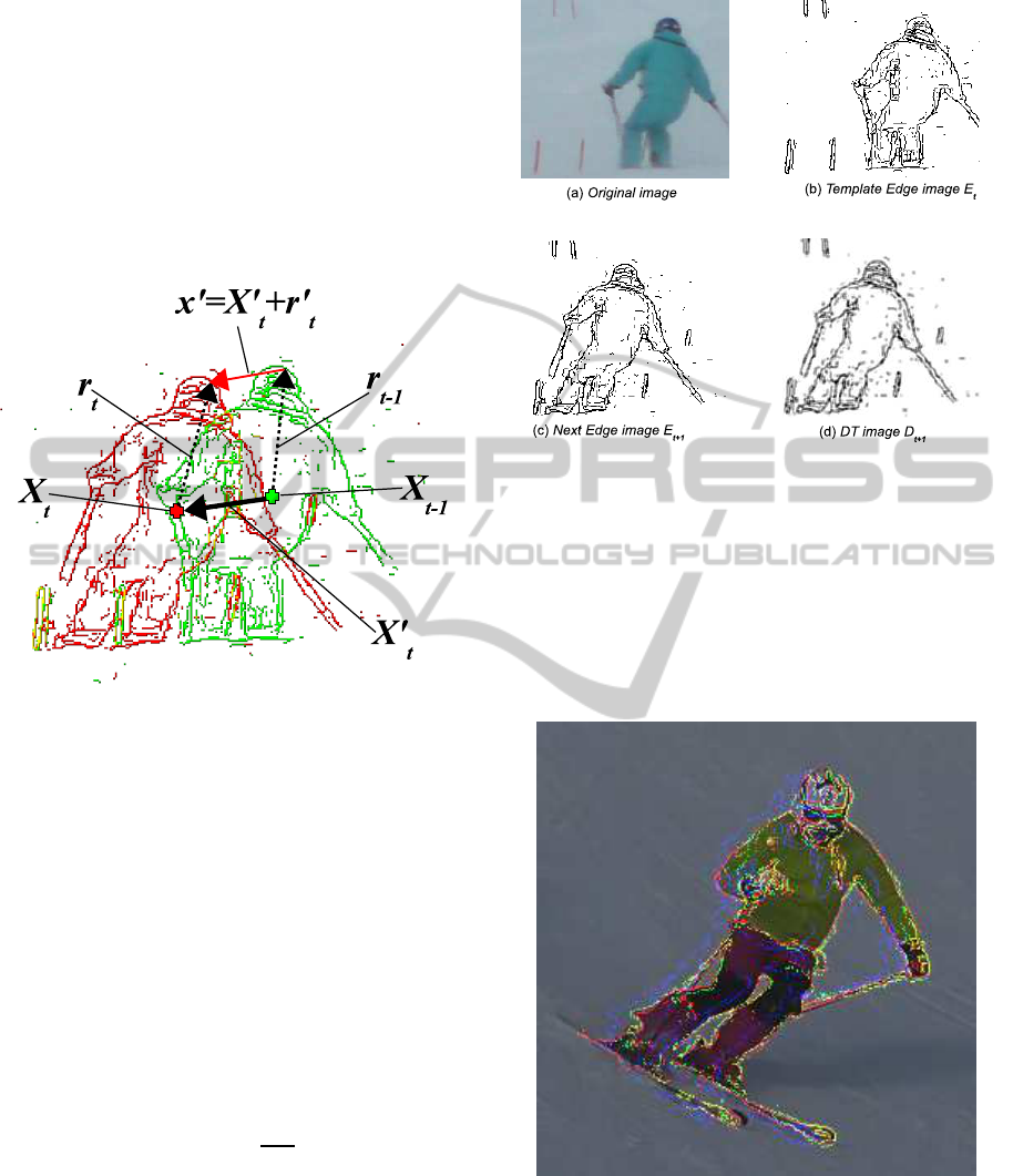
the prediction of the object shape. Figure 1 shows the
movement of the feature point x
′
, the movementof the
object’s center, X
′
, and the relative movement r
′
.
Figure 1: Edge image and object movement.
Green: Edge image for t −1, Red: Edge image for t
The similarity between the predicted edge image
ˆ
E
t+1
and actual edge image E
t+1
is measured by using
the Chamfer System (Gavrila, 2000). The Chamfer
System measures the similarity of two edge images
using distance transform methodology (DT) (Hutten-
locher et al. 1993).
Let us consider the problem of measuring the sim-
ilarity between template edge image E
t
(fig. 2(b)) and
a succeeding edge image E
t+1
(fig. 2(c)). We apply
the distance transform to obtain a DT image D
t+1
(fig.
2(d)), where each pixel value d
t+1
denotes the dis-
tance to the nearest feature pixel of E
t+1
. The chamfer
distance, D
chamf er
, is defined as
D
chamf er
(E
t
, E
t+1
) =
1
|E
t
|
∑
e∈E
t
d
t+1
(e) (5)
where |E
t
| denotes the number of feature points in
E
t
, e denotes a feature point of E
t
, and d
t+1
(e) de-
notes the chamfer distance between feature point e
and E
t+1
.
The translation of the object can be detected by
finding the position of the predicted edge image
ˆ
E
t+1
that minimizes the chamfer distance between it and
the actual edge image E
t+1
.
Figure 2: Chamfer system.
X
t+1
= arg min
X
t+1
D
chamf er
(
ˆ
E
t+1
(X
t+1
), E
t+1
). (6)
Figure 3 shows the tracking procedure, where the
blue edge represents the predicted edge image
ˆ
E, the
red edge represents the actual edge image E, and the
green edge represents the translated predicted edge
image
ˆ
E(X) according to equation (6).
Figure 3: Tracking procedure.
Blue: predicted edge image; Green: translated predicted edge
image; Red: reconstructed edge image.
2.3.1 Detection of Relative Movement
After the object translation X
′
t+1
is determined, the
relative movements of the feature points r
′
t+1
are de-
ICPRAM2014-InternationalConferenceonPatternRecognitionApplicationsandMethods
582
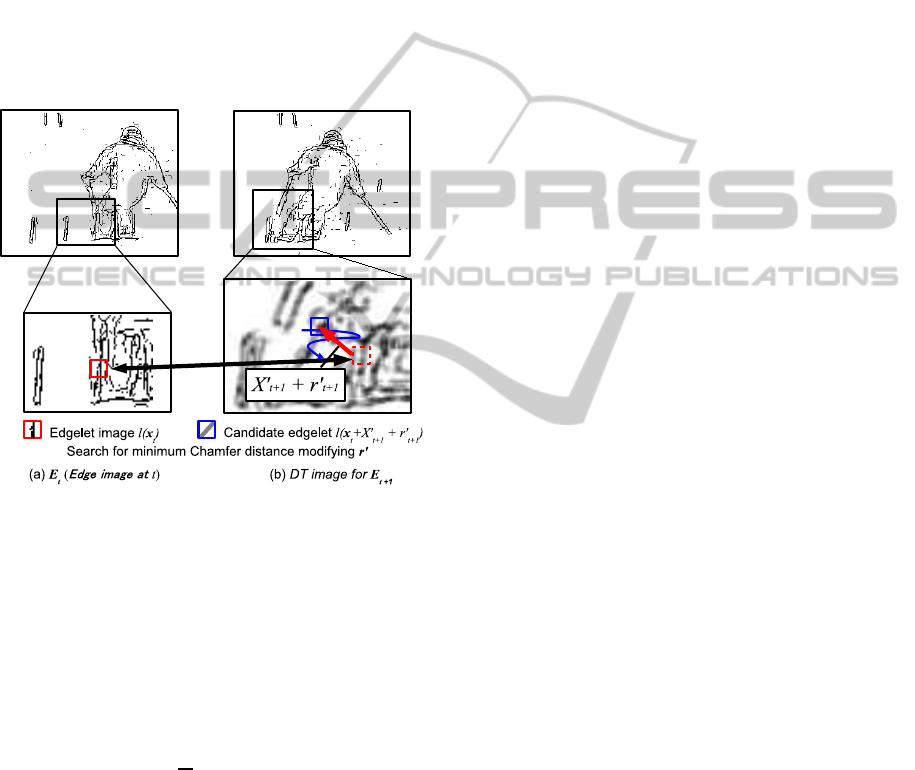
tected to determine the feature point movement x
′
t+1
.
The relative movement r
′
t+1
is detected using the ac-
tual edge image at t + 1 by tracking small parts of the
edge (edgelets). We also employed the Chamfer Sys-
tem (Gavrila, 2000) to detect the relative movement
of the edgelets.
When a template edgelet image l(˜x
t
) is extracted
from E
t
, the candidate edgelet l( ˜x
t
+ X
′
t+1
+
ˆ
r
′
t+1
) is
extracted from next edge image E
t+1
using X
′
as an
offset. The deformation of the object can be detected
by finding the edgelet pair such that the chamfer dis-
tance between the edgelet image in l( ˜x
t
) and the cor-
responding edgelet image in l( ˜x
t
+ X
′
t+1
+
ˆ
r
′
t+1
) (fig.
4):
Figure 4: Edgelet tracker.
ˆ
r
′
t+1
= arg min
ˆ
r
′
t+1
D
chamf er
(l( ˜x
t
), l( ˜x
t
+ X
′
t+1
+
ˆ
r
′
t+1
)),
(7)
Since the detected relative movements
ˆ
r
′
t+1
may
contain some noise, smoothing is applied by taking an
average of the relative movements in the neighboring
region.
r
′
t+1
=
1
N
∑
ˆr
′
t+1
∈δ
t+1
ˆr
′
t+1
, (8)
where N stands for the number of detected relative
movements ˆr
′
t+1
in the neighborhood δ of ˜x
t
.
Finally, the feature point movement x
′
t+1
is deter-
mined by summing the object translation X
′
t+1
and the
relative movement r
′
t+1
,
x
′
t+1
= X
′
t+1
+ r
′
t+1
. (9)
3 EXPERIMENTAL RESULTS
The proposed algorithm was applied to two video se-
quences of skiing, one of which was a sequence cap-
tured by a hand-held camera, while the other was a
sequence captured by a fixed camera. The effect of
the ego-motion of the camera was examined in the
sequence of the hand-held camera, and the tracking
performance for the skier’s movement was examined
in the sequence of the fixed camera.
3.1 Video Sequence of Hand-held
Camera
We first examined the video sequence captured by the
hand-held camera. In this sequence, the skier was
manually tracked so as to be shown near the center
of the image frame, and thus, the object tends to have
a small translation in the image frame. However, the
object sometimes has a large translation caused by the
mis-tracking of the camera. Figure 5 shows the track-
ing result. The blue edge represents the predicted ob-
ject shape, the green edge represents the translated
predicted shape to determine the object position using
equation (6), and the red edge represents the recon-
structed object shape, which is calculated by equation
(1) using the result of the final estimation obtained
using equation (9).
The results show that the proposed algorithm suc-
cessfully tracked the object with good prediction of
the shape. In the prediction phase for frame num-
ber 392, there was a significant error in the posi-
tion estimation, which may have been caused by the
large ego-motion that occurred between frames 391
and 392. However, the position of the object was
corrected by finding the appropriate position using
chamfer matching between the predicted and the ac-
tual edge image. The detected movements of the fea-
ture points can be verified by the reconstructed edge
image.
3.2 Video Sequence of Fixed Camera
Figure 6 shows the results for the video sequence cap-
tured by the fixed camera. Since the skier was not
tracked by the camera, the translation of the skier had
to be tracked. Although the results show that the ob-
ject was tracked successfully, there was some errors in
the shape prediction and reconstruction, such as that
of the legs in frames 52 and 54. It is considered that
difference in the movement of the ski pole and the
skier’s legs, which were very close together in frames
52 and 54, caused this error.
TrackingbyShapewithDeformingPredictionforNon-rigidObjects
583
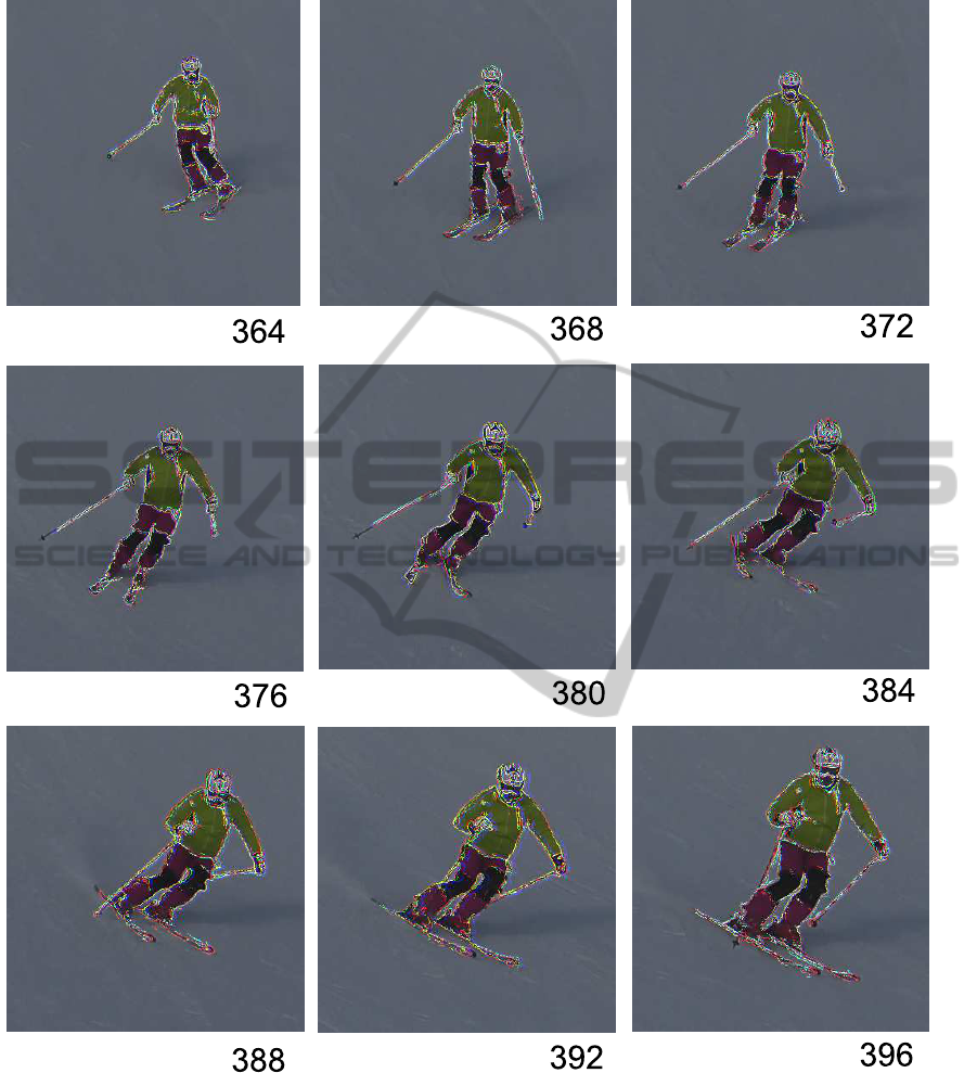
Figure 5: Tracking result for Hand-held camera.
Blue: predicted edge image; Green: translated predicted edge image; Red: reconstructed edge image.
4 DISCUSSION AND FUTURE
WORK
Although in some previous studies on shape predic-
tion, such as those of (Sim and Sundaraj, 2010) and
(Sundarmoorthi et al. 2010), only a first order differ-
ential (optical flow) was adopted, we adopted up to
second order differentials for shape prediction.
The effect of second order differentials is indi-
cated in fig. 7, where the blue edge represents the
ground truth, the green edge represents the prediction
when only the first order differential is adopted, and
the red edge represents the prediction with up to sec-
ICPRAM2014-InternationalConferenceonPatternRecognitionApplicationsandMethods
584
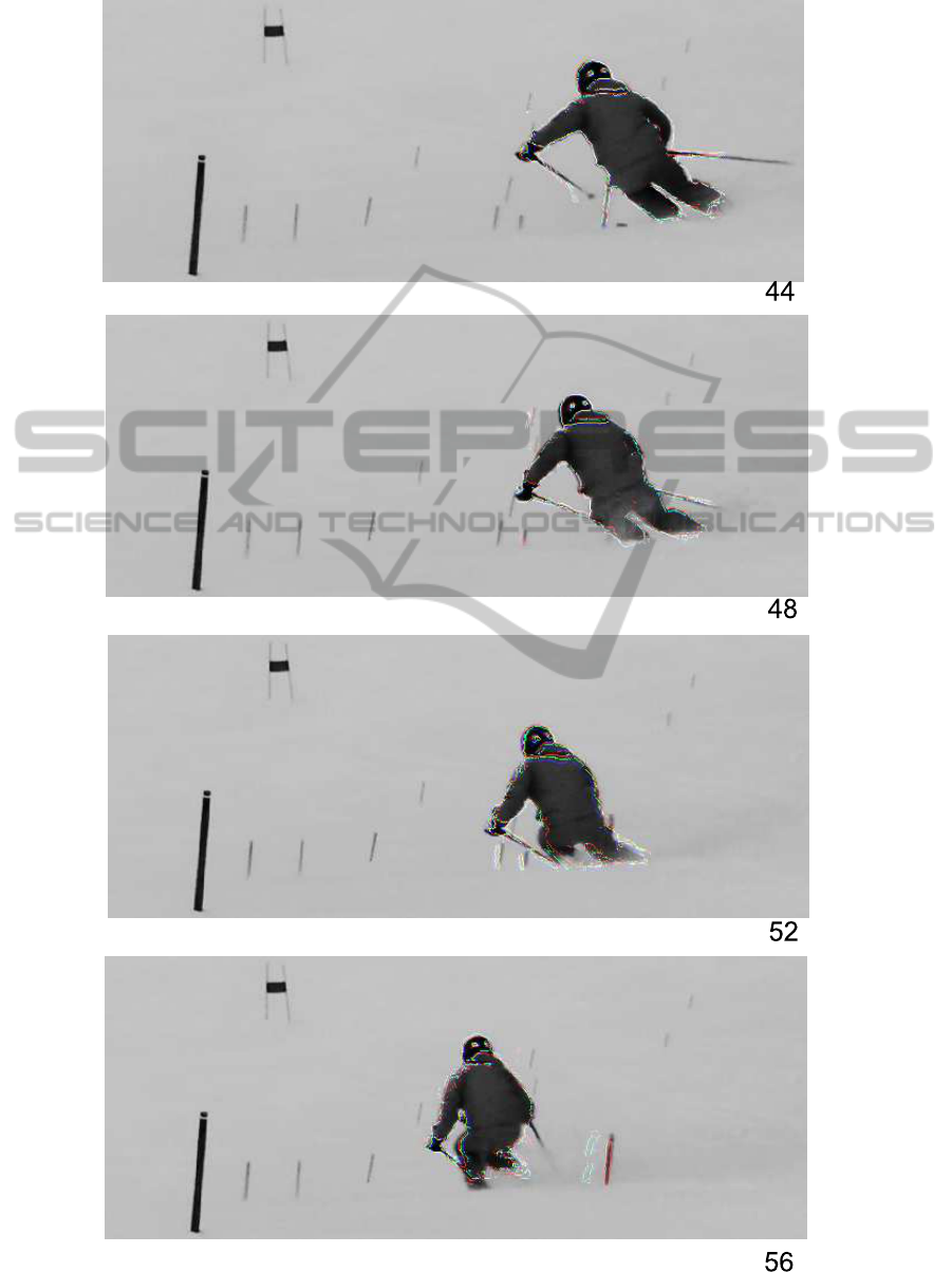
Figure 6: Tracking result for fixed camera.
Blue: predicted edge image; Green: translated predicted edge image; Red: reconstructed edge image.
TrackingbyShapewithDeformingPredictionforNon-rigidObjects
585
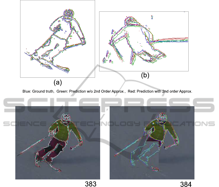
Figure 7: Effect of 2nd order approximation for shape prediction.
Figure 8: Occlusion recovery.
ond order differentials. Both the results in fig. 7 indi-
cate that the shape prediction accuracy was improved
by adopting the second order differential.
Occlusion recovery is one of the important issues
related to tracking algorithms. Since our algorithm
predicts the object shape from the preceding video
frames, it is possible to predict the shape of an oc-
cluded object. Figure 8 shows that the proposed algo-
rithm predicts the shape of the object that is artificially
occluded in video frame 384.
5 CONCLUSIONS
In this paper, we proposed a tracking algorithm using
shape matching between the predicted and the actual
object in the next video frame. In the proposed algo-
rithm, second order approximation for shape predic-
tion was adopted and the algorithm attained a good
tracking performance. Because of the accurate shape
prediction, the proposed algorithm showed that it is
possible to recover the shape of an object in occluded
regions.
REFERENCES
Authors, submitted to VISAPP 2014.
S.Avidan, “Ensemble Tracking”, IEEE PAMI, Vol.29, No.2,
pp.261,271, 2007.
D.Beymer, et al., “A Real-Time Computer Vision Sys-
tem for Measuring Traffic Parameters”, in Proc. IEEE
CVPR, pp.495-501, 1997.
T. Brox, C. Bregler, and J. Malik, “Large Displacement
Optical Flow”, in Proc. CVPR 2009, pp. 41-48, 2009.
B.Coifman, et al., “A Real-time Computer Vision System
ICPRAM2014-InternationalConferenceonPatternRecognitionApplicationsandMethods
586

for Vehicle Tracking and Traffic surveillance”, Trans-
portation Research Part C, No.6, pp.271-288, 1998.
R.T.Collins, et al., “Online Selection of Discriminative
Tracking Features”, in IEEE PAMI, Vol.27, No.10,
pp.1631-1643, 2005.
D. Comaniciu, V. Ramesh, and P. Meer,. “Real-Time Track-
ing of Non-Rigid Objects using Mean Shift”, in Proc.
CVPR 2000, pp. 142-149, 2000.
D.Comeniciu, P.Meer, “MeanShift: A Robust Approach To-
ward Feature Space Analysis”, IEEE PAMI, Vol.24,
No.5, pp.603-619, May, 2002.
D.M. Gavrila, “Pedestrian Detection from a Moving Vehi-
cle”, in Proc. ECCV 2009, pp. 37-49, 2009.
M. Godec, P.M Roth, and H.Bischof, “Hough-based Track-
ing on Non-rigid Objects”, to appear in J. of Computer
Vision and Image Understanding, available online, El-
sevier, 2013.
H.Grabner, M.Grabner, H.Bischof, “Real-Time Tracking
via On-line Boosting”, in Proc. BMVC, pp.47-56,
2006.
H.Grabner, C.Leistner, H.Bischof, “Semi-Supervised On-
Line Boosting for Robust Tracking”, in Proc. ECCV
2008, pp.234-247, 2008.
D.Huttenlocher, G.Klanderman, and W.J.Rucklidge, “Com-
paring Images using the Hausdorff Distance”, in IEEE
Trans. on Pattern Analysis and Machine Intelligence,
Vol. 15, No. 9, pp. 850-863, 1993.
Z.Kim, J.Malik, “Fast Vehicle Detection with Probabilis-
tic Feature Grouping and its Application ot Vehicle
Tracking”, in Proc. ICCV, pp.524-531 2003.
D.Koller, J.Weber, J.Malik, “Robust Multiple Car Tracking
with Occlusion Reasoning”, in proc. ECCV, Vol.A,
pp.189-196, 1994.
V.Mahadevan, N.Vasconcelos, “Salliency-based Discrimi-
nant Tracking”, in Proc.of CVPR 2009, pp.1007-1013,
2009.
A. Mohan, C. Papageorgiou, and T. Poggio, “Example-
based Object Detection in Images by Components”,
in IEEE Trans. Pattern Analysis and Machine Learn-
ing’, Vol. 23, No. 4, pp. 349-361, 2001.
K.F. Sim, and K. Sundaraj,. “Human Motion Tracking of
Athlete Using Optical Flow & Artificial Markers”, in
Proc. ICIAS 2010, pp. 1-4, 2010.
G.Sundaramoorthi, A.Mennucci, S.Soatto, A.Yezzi, “A
New Geometric Metric in the Space of Curves, and
Applications to Tracking Deforming Objects by Pre-
diction and Filtering”, in SIAM j. of Imaging Science,
Vol.4, No.1, pp.109-145, 2010.
T.Woodley, B.Stenger, R.Chipolla, “Tracking using Online
Feature Selection and a Local Generative Model”, in
Proc. BMVC 2007, 2007.
TrackingbyShapewithDeformingPredictionforNon-rigidObjects
587
