
Real-time Pedestrian Detection in a Truck’s Blind Spot Camera
Kristof Van Beeck and Toon Goedem´e
EAVISE, Campus De Nayer - KU Leuven, J. De Nayerlaan 5, 2860 Sint-Katelijne-Waver, Belgium
ESAT-PSI, KU Leuven, Kasteel Arenbergpark 10, 3100 Heverlee, Belgium
Keywords:
Pedestrian Detection, Tracking, Real-time, Computer Vision, Active Safety Systems.
Abstract:
In this paper we present a multi-pedestrian detection and tracking framework targeting a specific application:
detecting vulnerable road users in a truck’s blind spot zone. Research indicates that existing non-vision based
safety solutions are not able to handle this problem completely. Therefore we aim to develop an active safety
system which warns the truck driver if pedestrians are present in the truck’s blind spot zone. Our system solely
uses the vision input from the truck’s blind spot camera to detect pedestrians. This is not a trivial task, since
the application inherently requires real-time operation while at the same time attaining very high accuracy.
Furthermore we need to cope with the large lens distortion and the extreme viewpoints introduced by the blind
spot camera. To achieve this, we propose a fast and efficient pedestrian detection and tracking framework
based on our novel perspective warping window approach. To evaluate our algorithm we recorded several
realistically simulated blind spot scenarios with a genuine blind spot camera mounted on a real truck. We
show that our algorithm achieves excellent accuracy results at real-time performance, using a single core CPU
implementation only.
1 INTRODUCTION
Fast and meanwhile accurate pedestrian detection is
necessary for many applications. Unfortunately these
two demands are contradictory, and thus very diffi-
cult to unite. Even with today’s cheaply available
computational power it remains very challenging to
achieve both goals. Indeed, recent state-of-the-art
pedestrian detectors achieving real-time performance
heavily rely on the use of parallel computing de-
vices (e.g. multicore CPUs or GPUs) to perform this
task. This often makes it unfeasible to use these algo-
rithms in real-life applications, especially if these ap-
plications rely on embedded systems to perform their
tasks.
In this paper we propose an efficient multi-
pedestrian detection and tracking framework for a
specific application: detection of pedestrians in a
truck’s blind spot zone. Statistics indicate that in
the European Union alone, these blindspot accidents
cause each year an estimated 1300 casualties (EU,
2006). Several commercial systems were developed
to cope with this problem, both active and passive
systems. Active safety systems automatically gen-
erate an alarm if pedestrians enter dangerous zones
around the truck (e.g. ultrasonic distance sensors),
whereas passive safety systems still rely on the focus
of the truck driver (e.g. blind spot mirrors). How-
ever, none of these systems seem to adequately cope
with this problem since each of these systems have
their specific disadvantages. Active safety systems
are unable to interpret the scene and are thus not able
to distinguish static objects from actual pedestrians.
Therefore they tend to generate many false alarms
(e.g. with traffic signs). In practice the truck driver
will find this annoying and often disables these type
of systems. Existing passive safety systems are far
from the perfect solution either. In fact, although
blind spot mirrors are obliged by law in the European
Union since 2003, the number of casualties did not
decrease (Martensen, 2009). This is mainly due to the
fact that these mirrors are not adjusted correctly; re-
search indicates that truck drivers often use these mir-
rors to facilitate maneuvering. A passive blind-spot
camera system with a monitor in the truck’s cabin is
always adjusted correctly, however it still relies on the
attentiveness of the driver.
To overcome these problems we aim to develop
an active safety system based on the truck’s blind
spot camera. Our final goal is to automatically de-
tect vulnerable road users in the blind spot camera im-
ages, and warn the truck driver about their presence.
Such an active safety system has multiple advantages
412
Van Beeck K. and Goedemé T..
Real-time Pedestrian Detection in a Truck’s Blind Spot Camera.
DOI: 10.5220/0004821304120420
In Proceedings of the 3rd International Conference on Pattern Recognition Applications and Methods (ICPRAM-2014), pages 412-420
ISBN: 978-989-758-018-5
Copyright
c
2014 SCITEPRESS (Science and Technology Publications, Lda.)
over existing systems: it is independent of the truck
driver, it is always adjusted correctly and it is eas-
ily implemented in existing passive blind spot camera
systems. Due to the specific nature of this problem,
this is a challenging task. Vulnerable road users are a
very diverse class: besides pedestrians also bicyclists,
mopeds, children and wheelchair users are included.
Furthermorethe specific position and type of the blind
spot camera induces several constraints on the cap-
tured images. These wide-angle blind spot cameras
introduce severe distortion while the sideway-looking
view implies a highly dynamical background. See
figure 1 for an example frame from our blind spot
dataset.
However, the most challenging part is undoubtly
the hard real-time constraint, combined with the need
for high accuracy. In this paper we present part
of such a total safety solution: we propose an effi-
cient multi-pedestrian tracking- and detection frame-
work based on blind spot camera images. Our algo-
rithm achieves both high accuracy and high detection
speeds. Using a single-core CPU implementation we
reach an average of 13 FPS on our datasets.
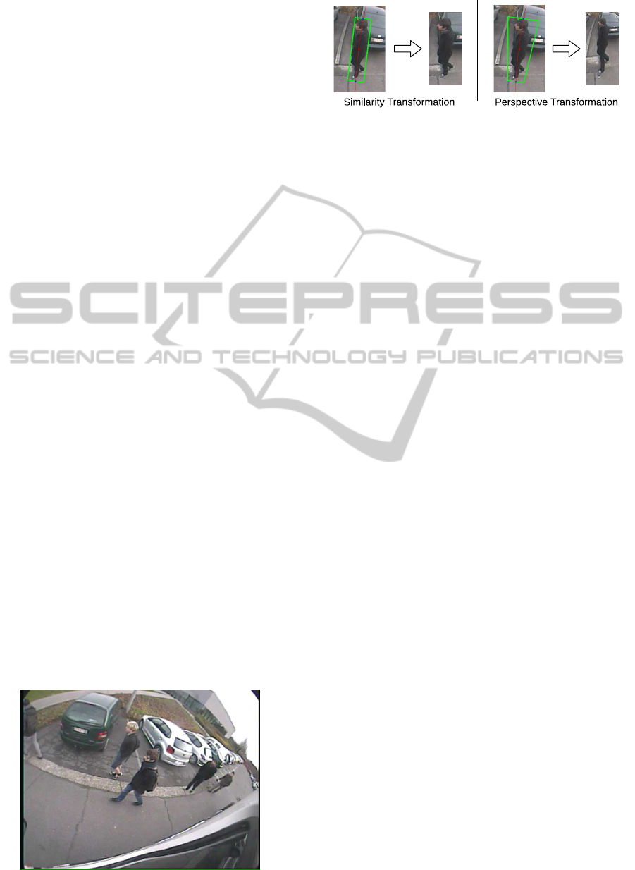
In previous work (Van Beeck et al., 2011; Van
Beeck et al., 2012) we proposed our initial warp-
ing window approach. However, this initial approach
was based solely on a naive similarity warp, running
up against its limit (e.g. w.r.t. accuracy for our ap-
plication). In this paper we propose our perspec-
tive warping window approach: we extensively re-
designed and improved our previous work making it
more elegant and accurate, without significantly in-
creasing the algorithmic complexity. Moreover, we
even obtain higher computation speeds. Figure 2 con-
cisely compares our previous and our improved novel
approach presented here.
Our proposed algorithm briefly works as follows.
Traditional state-of-the-art pedestrian detectors use a
sliding window paradigm: each possible position and
scale in the image is evaluated. This however is un-
feasible in real-time applications. Instead, we pro-
Figure 1: Example frame from our blind spot camera.
Figure 2: Similarity vs perspective transformation model.
posed our warping window approach: we eliminate
the need to perform a full scale-space search using the
exploitation of scene constraints. That is, at each posi-
tion in the input image we locally model the transfor-
mation induced by the distortion. During detection,
we can then warp the regions of interest (ROIs) in the
image and use a standard pedestrian detector at a sin-
gle scale on each ROI.
This approach is integrated in a tracking-by-detection
framework and combined with temporal information,
making it more robust while reducing the detection
time. We performed extensive experiments to eval-
uate our algorithm concerning both speed and accu-
racy. For this we recorded several realistically simu-
lated dangerous blind spot scenarios.
The remainder of this paper is organised as fol-
lows. In the next section we describe related work
concerning this topic. Section 3 describes our algo-
rithm in more detail, while in section 4 we propose
our experiments and evaluation results. We then con-
clude our work in section 5.
2 RELATED WORK
In the past few years the accuracy of pedestrian detec-
tors has been significantly improved. Currently, even
on challenging datasets excellent accuracy results are
presented (Doll´ar et al., 2012).
Initially, Dalal and Triggs proposed a pedestrian
detection framework based on the Histograms of Ori-
ented Gradients (HOG) combined with an SVM (Sup-
port Vector Machine) for classification (Dalal and
Triggs, 2005). This idea was further refined in Felzen-
szwalb et al. (2008) where the authors extended the
concept with a part-based HOG model rather than
a single rigid template. Evidently, this increases
calculation time. To partially cope with this prob-
lem they proposed a more efficient cascaded frame-
work (Felzenszwalb et al., 2010). Apart from increas-
ing the model complexity, one can opt to increase the
number of features to improve detection accuracy. In-
deed, such a detector is presented in (Doll´ar et al.,
2009a), called Integral Channel Features. However,
each of these detectors still uses a sliding window ap-
Real-timePedestrianDetectioninaTruck'sBlindSpotCamera
413

proach. Across the entire image the features are cal-
culated at all scales. To avoid such an exhaustive full
scale-space search several optimisation techniques
were proposed; e.g. Lampert et al. (2009) proposed
an efficient subwindowsearch. Doll´ar et al. (2010)in-
troduced the Fastest Pedestrian Detector in the West
(FPDW) approach, in which they approximate fea-
ture responses from scales nearby thus eliminating the
need to fully construct the scale-space pyramid. Ex-
tensive comparative works have been published (En-
zweiler and Gavrila, 2009; Doll´ar et al., 2009b) to de-
termine the most accurate approach. Both conclude
that the HOG-based approach outperforms existing
methods.
More recently, a benchmark between six-
teen state-of-the-art pedestrian detectors was pre-
sented (Doll´ar et al., 2012). The authors conclude
that part-based HOG detectors still achieve the high-
est accuracy, while the FPDW is one order of mag-
nitude faster with only small loss in accuracy. Based
on these conclusions we chose the part-based HOG
model as the base detector in our framework.
Concerning speed, several GPU optimisations
were proposed. Prisacariu and Reid (2009) proposed
a fast GPU implementation of the standard HOG
model. Pedersoli et al. (2013) presented a pedestrian
detection system using a GPU implementation of the
part-based HOG model. Benenson et al. (2012a) pro-
posed work in which they perform model rescaling
instead of image rescaling, and combined with their
stixel world approximation they achieve fast pedes-
trian detection (Benenson et al., 2012b). Recently
the authors proposed their Roerei detector (Benen-
son et al., 2013). Based on a single rigid model they
achieve excellent accuracy results. However, in real-
life applications using embedded systems such high-
end GPU computing devices are often not available.
Therefore our algorithm focuses on real-time perfor-
mance, while maintaining high accuracy, on standard
hardware.
Speed optimisation is also achieved using pedes-
trian tracking algorithms, of which several are pro-
posed in the literature. They often rely on a fixed
camera, and use a form of background modelling
to achieve tracking (Viola et al., 2005; Seitner and
Hanbury, 2006). Since in our application we have
to work with moving camera images, this cannot be
used. Pedestrian tracking algorithms based on mov-
ing cameras mostly use a forward-looking view (Ess
et al., 2008) or employ disparity information (Gavrila
and Munder, 2007). Cho et al. (2012) proposed a
pedestrian tracking framework related to our work,
exploiting scene constraints to achieve real-time de-
tection. However, they use a basic ground-plane as-
sumption whereas our approach is much more flexi-
ble and generic. Moreover, our specific datasets are
much more challenging due to the severe distortion.
We significantly differ from all of the previously
mentioned approaches. We aim to develop a monoc-
ular multi-pedestrian tracking framework with a chal-
lenging backwards/sideways looking view, targeting
high accuracy at real-time performance. Furthermore,
most of these classic sliding window approaches as-
sume only object scale variation. Other geometri-
cal variations (e.g. rotation (Huang et al., 2005) and
aspect ratio (Mathias et al., 2013)) are usually cov-
ered by an exhaustive search approach. Our proposed
warping approach offers a solution that can even cope
with perspective distortion. In fact, without our warp-
ing window paradigm it would be unfeasible in prac-
tice to perform such an exhaustivesearch in a perspec-
tive distortion space.
3 ALGORITHM OVERVIEW
As mentioned above, existing pedestrian detectors
employ a sliding window approach. Across all po-
sitions and scales in the image the features are calcu-
lated and evaluated, making it almost impossible to
meet the stringent real-time demands needed in most
safety applications. To achieve real-time detection
speeds with high accuracy we propose our novel per-
spective warping window approach.
Our idea is mainly based on the following obser-
vation. Looking at an example frame from our dataset
(see figure 1) one clearly notices that the pedestrians
appear rotated, scaled and perspectively transformed.
This is due to the specific position and the wide-angle
lens of our blind spot camera. The crux of the mat-
ter is that this transformation only depends on the
position in the image. Thus each pixel coordinate
x = [x, y] uniquely defines the transformation at that
specific position. If at each pixel position this trans-
formation is known, we can dramatically speedup
pedestrian detection. Based on this transformation
we can locally warp each region of interest to upright
pedestrians at a fixed height, and run a single-scale
pedestrian detector on each warped ROI image patch.
This approach effectively eliminates the need to con-
struct a scale-rotation-transformation-space pyramid,
and thus is very fast. Moreover, this approach is eas-
ily generalisable to other applications where such dis-
tortion occurs due to non-standard camera viewpoints
and/or wide-angle lens distortions (e.g. surveillance
cameras). To determine this transformation at each
pixel coordinate a one-time calibration step is needed.
To further increase both accuracy and speed, we inte-
ICPRAM2014-InternationalConferenceonPatternRecognitionApplicationsandMethods
414
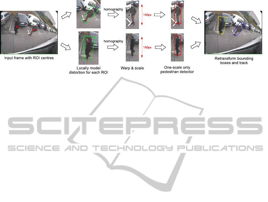
Figure 3: Illustration of our novel perspective warping window approach. At each position in the image we locally model the
distortion, warp the ROIs to a standard scale and use a one-scale only pedestrian detector.
grate this warping window approach into an efficient
tracking-by-detection framework. We use temporal
information to predict future positions of pedestrians,
thus further reducing the search space. Below we de-
scribe these steps in more detail. In subsection 3.1 we
describe how our new perspective warping approach
models the transformation, and motivateimportant al-
gorithmic design choices such as the pedestrian detec-
tor, and the optimal scale parameter. In subsection 3.2
we then show how we integrate each of these steps
into our total framework, thus describing our com-
plete algorithm.
3.1 Warp Approach
Figure 3 illustrates our perspective warping window
approach. Starting from input images as given in
figure 1, pedestrians appear rotated, scaled and per-
spectively distorted. If we assume a flat ground-
plane, these transformation parameters only depend
on the specific position in the image. If we know
the transformation we can model the perspective dis-
tortion for that ROI, extract and warp the ROI im-
age patch to a fixed-scale (160 pixels - motivated fur-
ther in this work) and perform pedestrian detection
on a single scale only. We thus eliminate the need
to construct a scale-space pyramid. Note that, al-
though we perform detection on a single scale only,
the pedestrian model still provides some invariance
with respect to the pedestrian height. However, if
large deviations from the standard height (e.g. chil-
dren) need to be detected, an extra scale needs to be
evaluated. The coordinates of the detected bounding
boxes are then retransformed and fed into our track-
ing framework. Next we describe further details of
our algorithm: how this position-specific transforma-
tion is mathematically modeled and how the calibra-
tion is performed. We further motivate the choice of
our baseline pedestrian detector and determine the op-
timal fixed-height parameter.
Transformation Modelling. Figure 4 illustrates how
the transformation is locally modeled. We use a
perspective distortion model in the lens-distortion-
corrected image. At each position, the height and
width (at the ground) are known after a one-time cali-
bration step (see further). These are visualised as two
heat maps (the so-called look-up-functions or LUFs)
in figure 4. The transformation coordinates are de-
termined as follows. Each ROI centre coordinate (in-
dicated with the red asterisk in the leftmost image) is
first transformed into the undistorted image. This lens
undistortion is simply based on the traditionally used
radial lens distortion model:
x
′
= x(1+ k
1
r
2
+ k
2
r
4
) (1)
r
2
= x
2
+ y
2
(2)
Here, x
′
denotes the corrected pixel coordinate, x the
input coordinate and k
1
and k
2
indicate the radial dis-
tortion coefficients.
Next we calculate the vantage line through this ROI
centre in the undistorted image, and determine the
height and width (at the bottom) from the two LUFs.
Based on these data we construct the perspective
model in the undistorted image. The rotation of the
image patch is determined from the angle of the van-
tage line, and the length ratio between the top and
bottom is calculated based on the distance to the van-
tage point (visualised in the middle of figure 4). We
thus locally model the pedestrians as if they are pla-
nar objects standing upright, faced towards the cam-
era (that is, perpendicular to the optical axis of our
blind spot camera). Our experiments show that this
is a valid approximation for pedestrians. These coor-
dinates are then retransformed to the distorted input
image. Note that evidently only the coordinates are
transformed, the middle image displayed here is only
used for visualisation purposes. Based on the coordi-
nates in the distorted image, and the known calibra-
tion data we apply a homography on the ROI image
patch, thereby effectively undoing the local perspec-
tive distortion (visualised in fig. 3).
Real-timePedestrianDetectioninaTruck'sBlindSpotCamera
415
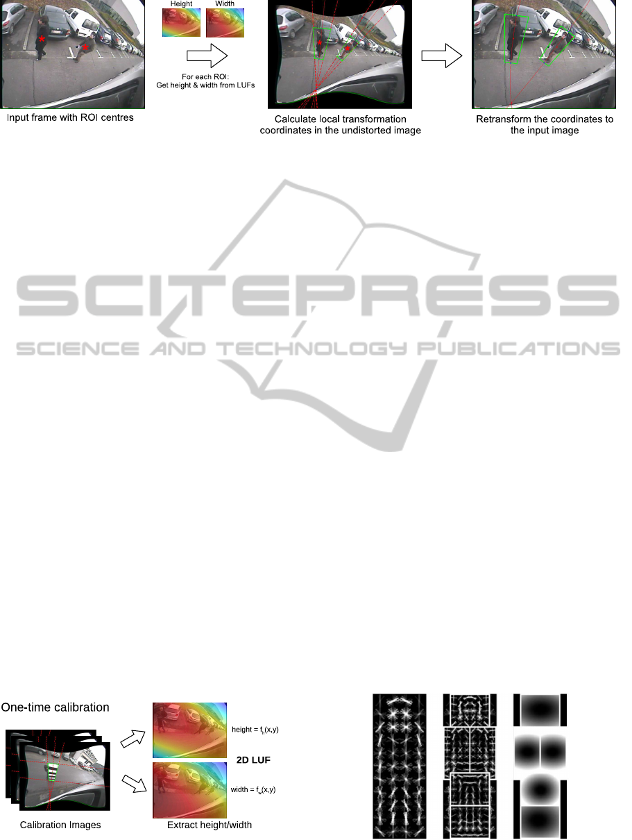
Figure 4: The transformation is modeled as a perspective transformation, calculated in the undistorted image.
Calibration. To obtain these two LUFs, a one-time
calibration step is needed. To achieve this, we man-
ually annotated about 200 calibration images. We
utilised a planar calibration board of 0.5×1.80m, and
captured calibration positions homogeneously spread
over the entire image (figure 5). The labeling was
performed in the undistorted image. These images
yield the vantage point, and the height and width of
a pedestrian (at the ground) at each position for that
image. Next we interpolated these datapoints using
two-dimensional second order polynomial functions
for both the height and the width: f
h
(x, y) and f
w
(x, y)
with:
f
i
(x, y) = p
0
+ p
1
x+ p
2
y+ p
3
x
2
+ p
4
xy+ p
5
y
2
(3)
Both functions are displayed as heat maps in figure 5:
for each pixel coordinate they effectively give the
height and width of the calibration pattern at that lo-
cation. If for some reason the position of the camera
w.r.t. the ground place changes, a recalibration needs
to be performed. This is highly unlikely though, due
to the robust camera mounting on the truck. Thus to
summarise, detection is composed of four different
steps: calculate the local perspective distortion model
at each ROI centre, perform a homography and trans-
form the pedestrians to an undistorted, upright posi-
tion at a fixed height of 160 pixels, run a pedestrian
detector at one scale, and finally retransform the coor-
dinates of the detected bounding boxes to the original
input image.
Pedestrian Detector. Based on the comparative
works given in section 2 we conclude that, since we
Figure 5: A one-time calibration is needed to determine the
local perspective distortion.
aim for high accuracy, HOG models are most suited.
The FPDW has only slightly lower accuracy and is
much faster. However, since we need to evaluate only
one scale, no feature pyramid is constructed, thus
this speed advantage is here not relevant. Since we
know the scale at each position, this allows us to use
a pedestrian detector with very high accuracy, which
would otherwise be too computationally expensive
for real-time operation. Thus, the choice for our
baseline pedestrian detector goes to the top-accuracy
state-of-the-art HOG based detector: the cascaded
part-based HOG detector from (Felzenszwalb et al.,
2010). Let us briefly discuss how this pedestrian
detector works. The detector uses a pretrained model,
consisting of HOG features (see fig. 6). It consists of
a root filter and a number of part filters representing
the head and limbs of the pedestrian. To use this
model, first a scale-space pyramid is constructed,
using repeated smoothing and subsampling. For each
pyramid layer the HOG features are computed. Then,
for a specific scale the response of the root filter and
the feature map is combined with the response of
the part filters to calculate a final detection score.
On our 640 × 480 resolution images this detector
off-the-shelf needs an average of 2.3s per frame,
while their cascaded version (which we use in our
framework) needs on average 0.67s per frame. We
altered this detector into a single-scale detector and
when used in our framework we achieve real-time
performance (see section 4).
Figure 6: The pedestrian model of our detector. (L) Root
filter (M) Part filters (R) Score distribution over parts.
ICPRAM2014-InternationalConferenceonPatternRecognitionApplicationsandMethods
416
6080100120140160180200
0
0.1
0.2
0.3
0.4
0.5
0.6
0.7
0.8
0.9
1
Height of pedestrian (pixels)
Accuracy
Accuracy versus pedestrian resolution
Similarity Model
Perspective Model
Combination
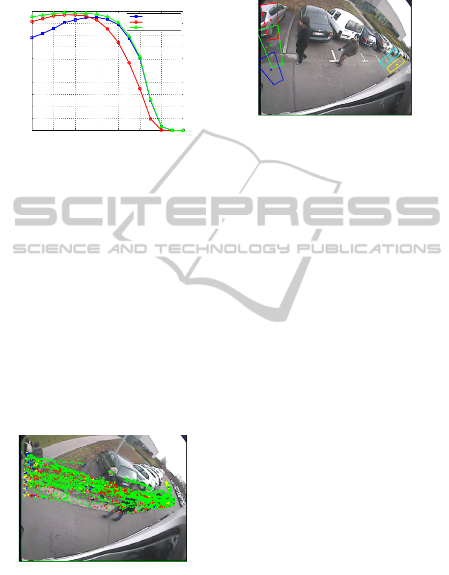
Figure 7: Determining the optimal scale parameter.
Determining the Optimal Scale Factor. As al-
ready mentioned, we rescale the pedestrians to a fixed
height. For this, an optimal value needs to be de-
termined. To achieve this, we extracted 6000 pedes-
trian images from our dataset, and performedthe warp
operation as given above. These pedestrians were
warped to fixed heights, and we then performed accu-
racy measurements to determine the optimal height.
Besides our novel perspective transformation model
presented in this paper, we also warped the pedestri-
ans using the similarity transformation model as ex-
plained in (Van Beeck et al., 2012), simply consist-
ing of a rotation and scaling operation (see fig. 2 for
a qualitative comparison). This was done to analyse
the benefit of our more complex perspective model.
Figure 7 displays our results. Besides the individual
transformations, we also give the combined accuracy.
Note that the optimal resolution of the perspectiveand
similarity transformation model differs. For the first
the optimal height lies at 160 pixels, whereas the lat-
ter reaches its optimum at 140 pixels. As can be seen,
Figure 8: Performance of the two transformation models in
function of the position. Colored dots indicate which model
performed the detection. Red: perspective model. Blue:
similarity model. Green: both models. Yellow indicates
missed detections.
Figure 9: Example of five initialisation coordinates together
with their corresponding transformation ROIs.
the perspective model has a clear accuracy advantage
over the similarity model. If both models were com-
bined, an even higher accuracy is achieved. This,
however, would double the calculation time. Figure 8
shows where each model performs best in function
of the position in the image. Red dots indicate where
the perspectivemodel worked, blue where the similar-
ity model worked and green were both models found
the detection. Yellow indicates a missed detection.
The perspective model obviously performs much bet-
ter than the similarity model. The similarity model
performs slightly better only at the image border, due
to the small calibration error there. The perspective
model performs better close to the truck because of
the large amount of viewpoint distortion there. Note
that if we analyse positions where both models found
the detection, the perspective model achieves the best
detection score in 69% of these cases, further indicat-
ing its clear advantage over the similarity transforma-
tion model.
3.2 Tracking Framework
To further improve the accuracy and detection speed
we integrated our warping window approach in a
tracking-by-detection framework. This is imple-
mented as follows. Instead of a full frame search, we
use initialisation coordinates (which define transfor-
mation ROIs) at the border of the image, and initially
only perform detection there. See figure 9 for an ex-
ample. If a pedestrian is detected, a linear Kalman
filter is instantiated for this detection. As a motion
model we use a constant velocity assumption. Our
experiments indicate that this assumption holds for
our application. The state vector x
k
consists of the
centre of mass of each detection and the velocity:
x
k
=
x y v
x
v
y
T
. Based on the update equa-
tion ˆx
−
k
= Aˆx
k−1
we estimate the next position of the
pedestrian. Here, ˆx
−
k
indicates the a priori state esti-
mate and ˆx
k
indicates the a posterior state estimate, at
Real-timePedestrianDetectioninaTruck'sBlindSpotCamera
417
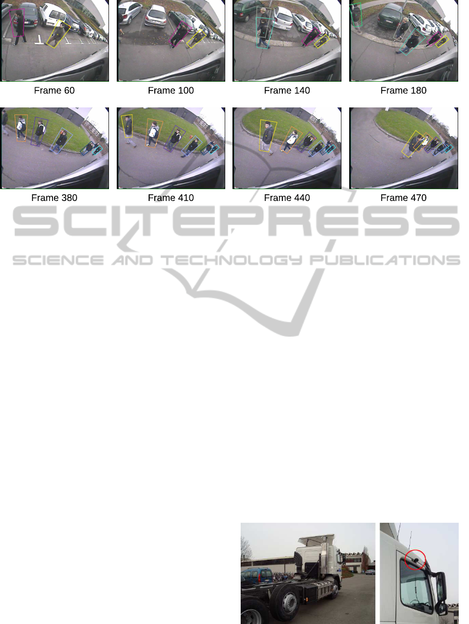
Figure 10: Qualitative tracking sequences over two of our datasets (top and bottom row) - see http://youtu.be/gbnysSoSR1Q
for a video.
timestep k. The process matrix A thus equals:
A =
1 0 1 0
0 1 0 1
0 0 1 0
0 0 0 1
(4)
Based on this motion model we predict the position
(that is, the centre of mass) of the pedestrian in the
next frame. Each estimated new pixel coordinate is
then used as input for our warping window approach:
we calculate the transformation model, warp the ROI
and perform pedestrian detection on this ROI. For
each pedestrian that is being tracked, our algorithm
verifies if a new detection is found. This is evaluated
by constructing a circular region around the estimated
coordinate based on the scale of that tracked instance.
If a new detection is found in this region, the Kalman
filter is updated and the new position is predicted. If
multiple detections are found, we associate the closest
based on the Euclidean distance. The bounding box
coordinates of tracked instances are averaged to as-
sure smooth transitions between frames. If for tracked
pedestrians no new detection is found, the Kalman fil-
ter is updated based on the estimated position. In this
case we apply a dynamic score strategy, and lower
the detection threshold for that instance (within cer-
tain boundaries). This ensures that pedestrians which
are difficult to detect (e.g. partially occluded or a tem-
porarily low HOG response) can still be tracked. If
no detection is found for multiple frames in a row,
the tracker is discarded. Evidently, if a new detection
is found for which no previous tracker exists, tracking
starts from there on. Figure 10 qualitatively illustrates
tracking sequences on two of our datasets.
4 EXPERIMENTS & RESULTS
We performed extensive experiments concerning both
speed and accuracy. Our datasets consists of simu-
lated dangerous blind spot scenarios, recorded with a
real truck. We used a commercial blind spot camera
(Orlaco CCC115
◦
) with a resolution of 640× 480 at
15 frames per second. This camera has a 115 degree
wide-angle lens. See figure 11 for the exact position
of the camera. Five different scenarios were recorded,
each in which the truck driver makes a right turn and
the pedestrians react differently (e.g. the truck driver
lets the pedestrians pass, or the truck driver keeps on
driving, simulating a near-accident). This resulted in
a total of about 11000 frames. For our accuracy and
speed experiments we labelled around 3200 pedestri-
ans. Our implementation is CPU-based only, and the
hardware consists of an Intel Xeon E5 CPU which
runs at 3.1 GHz. Note that all speed experiments are
performed on a single core. The algorithm is mainly
implemented in Matlab, with time-consuming parts
Figure 11: Our test truck with the mounted commercial
blind spot camera (circled in red).
ICPRAM2014-InternationalConferenceonPatternRecognitionApplicationsandMethods
418
0 0.2 0.4 0.6 0.8 1
0
0.2
0.4
0.6
0.8
1
Recall
Precision
Similarity Model (AP = 86.3%)
Perspective Model (AP = 92.3%)
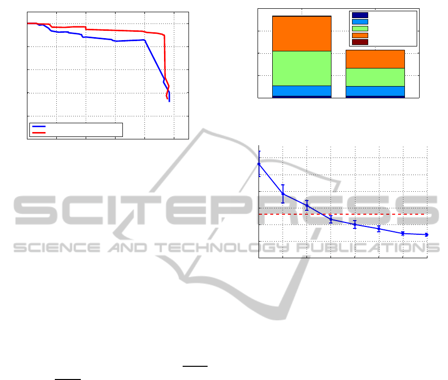
Figure 12: Precision-recall graph over our dataset.
(such as the homography) in OpenCV, using mex-
opencv.
Accuracy Results. Figure 12 displays the precision-
recall graph of our algorithm as calculated over our
datasets. The red PR curve indicates our novel per-
spective transformation approach, while the blue PR
curve represents our previous similarity transforma-
tion approach. They are calculated as follows. For
each detected pedestrian in our algorithm, we look for
a labeled instance in a circular region (based on the
scale) around the centre of our detection. If such an
instance is found, this is counted as being a true posi-
tive. If this is not the case, this detection is counted as
being a false positive. Each labeled pedestrian which
is not detected accounts for a false negative. The
PR-graph is then determined as: precision =
TP
TP+FP
and recall =
TP
TP+FN
. We notice that, although both
achieve very good accuracy results, our novel per-
spective warping window approach has a clear accu-
racy advantage over our similarity warping window
approach. Indeed, the average precision (AP) for the
similarity model equals 86.3%, whereas for the per-
spective model AP = 92.3%. With the perspective
model, at a recall rate of 94%, we still achieve a pre-
cision of 90%. Such high accuracy results are due to
our warping window approach. Since we know the
scale at each position, the number of false positives is
minimized. Furthermore this allows us to use a sensi-
tive pedestrian detection threshold.
Speed Results. As mentioned in section 3.1, if used
out-of-the-box the baseline pedestrian detector takes
670ms (i.e. 1.5 fps). Since in our framework we
only need to perform detection at a single scale and
ROI, the calculation time drastically decreases. For
each default search region and tracked pedestrian in
the image we need to perform a warp operation and
detection. Thus, the total calculation time evidently
Detection (avg 18.3 ms) No Detection (avg 10.8 ms)
0
5
10
15
20
Calculation time per ROI in ms
Calc. warp coord.
Perform warping
Calc. features
Model evaluation
Retransform coord.
Figure 13: Calculation time per ROI.
0 1 2 3 4 5 6 7
0
5
10
15
20
25
30
FPS versus # pedestrians
FPS
# pedestrians being tracked
Figure 14: Speed performance versus the number of tracked
pedestrians (dotted red line indicates the average fps).
depends on the number of tracked pedestrians per im-
age. Figure 13 displays the average calculation time
per ROI. Note that if a detection is found, the average
calculation time equals 18.3ms, while if no detection
is found the average calculation time drops to 10.8ms.
This calculation time per region is independent of the
position in the image. The average detection time
per ROI is subdivided into five steps: the calculation
of the warp coordinates, the time needed to perform
the warp operation, calculation of the HOG features,
evaluation of the pedestrian model, and finally the re-
transformation of the detected coordinates to the input
image. The total warp time (calc. warp coord. and
perform warping) only equals about 3 ms. Most time
is spent on the actual pedestrian detection. The time
needed to perform the retransformation of the coor-
dinates is negligible. Figure 14 displays the frames
per second as a function of the number of tracked
pedestrians we reached on our datasets. If no pedes-
trians are tracked we achieve 28.2 fps. On average we
achieve 13.0 fps (with an average of 3.4 pedestrians),
while our worst-case framerate equals 7.0 fps.
Real-timePedestrianDetectioninaTruck'sBlindSpotCamera
419

5 CONCLUSIONS & FUTURE
WORK
In this work we proposed a multi-pedestrian tracking
frameworkachievingexcellent accuracy and speed re-
sults on a single-core CPU implementation. The al-
gorithm is based on our novel perspective warping
window approach. We proposed this approach to al-
low for efficient pedestrian detection on the challeng-
ing, highly distorted camera images from a blind-spot
camera, with minimal CPU resources. However, this
approach is easily generalisable to other applications
with non-standard camera-viewpoints.
In the future we plan to further extend our framework
to multi-class detection: we aim to develop a com-
plete vulnerable road users detection system, starting
with bicyclists. Furthermore we aim to investigate
if the inclusion of other features (e.g. motion infor-
mation) could further increase the robustness of our
framework.
REFERENCES
Benenson, R., Markus, M., Tuytelaars, T., and Van Gool, L.
(2013). Seeking the strongest rigid detector. In Pro-
ceedings of CVPR, pages 3666–3673, Portland, Ore-
gon.
Benenson, R., Mathias, M., Timofte, R., and Van Gool, L.
(2012a). Fast stixels computation for fast pedestrian
detection. In ECCV, CVVT workshop, pages 11–20.
Benenson, R., Mathias, M., Timofte, R., and Van Gool, L.
(2012b). Pedestrian detection at 100 frames per sec-
ond. In Proceedings of CVPR, pages 2903–2910.
Cho, H., Rybski, P., Bar-Hillel, A., and Zhang, W. (2012).
Real-time pedestrian detection with deformable part
models. In IEEE Intelligent Vehicles Symposium,
pages 1035–1042.
Dalal, N. and Triggs, B. (2005). Histograms of oriented gra-
dients for human detection. In Proceedings of CVPR,
volume 2, pages 886–893.
Doll´ar, P., Belongie, S., and Perona, P. (2010). The fastest
pedestrian detector in the west. In Proceedings of
BMVC, pages 68.1–68.11.
Doll´ar, P., Tu, Z., Perona, P., and Belongie, S. (2009a). Inte-
gral channel features. In Proceedings of BMVC, pages
91.1–91.11.
Doll´ar, P., Wojek, C., Schiele, B., and Perona, P. (2009b).
Pedestrian detection: A benchmark. In Proceedings
of CVPR, pages 304–311.
Doll´ar, P., Wojek, C., Schiele, B., and Perona, P. (2012).
Pedestrian detection: An evaluation of the state of the
art. In IEEE PAMI, 34:743–761.
Enzweiler, M. and Gavrila, D. M.(2009). Monocular pedes-
trian detection: Survey and experiments. In IEEE
PAMI, volume 31, pages 2179–2195.
Ess, A., Leibe, B., Schindler, K., and Van Gool, L. (2008).
A mobile vision system for robust multi-person track-
ing. In Proceedings of CVPR, pages 1–8.
EU (22 february 2006). Commision of the european com-
munities, european road safety action programme:
mid-term review.
Felzenszwalb, P., Girschick, R., and McAllester, D. (2010).
Cascade object detection with deformable part mod-
els. In Proceedings of CVPR, pages 2241–2248.
Felzenszwalb, P., McAllester, D., and Ramanan, D. (2008).
A discriminatively trained, multiscale, deformable
part model. In Proceedings of CVPR.
Gavrila, D. and Munder, S. (2007). Multi-cue pedestrian de-
tection and tracking from a moving vehicle. In IJCV,
volume 73, pages 41–59.
Huang, C., Ai, H., Li, Y., and Lao, S. (2005). Vector boost-
ing for rotation invariant multi-view face detection. In
ICCV, pages 446–453.
Lampert, C., Blaschko, M., and Hoffmann, T. (2009). Effi-
cient subwindow search: A branch and bound frame-
work for object localization. In IEEE PAMI, vol-
ume 31, pages 2129–2142.
Martensen, H. (2009). Themarapport vracht-
wagenongevallen 2000 - 2007 (BIVV).
Mathias, M., Timofte, R., Benenson, R., and Van Gool, L.
(2013). Traffic sign recognition - how far are we from
the solution? In ICJNN.
Pedersoli, M., Gonzalez, J., Hu, X., and Roca, X. (2013).
Toward real-time pedestrian detection based on a de-
formable template model. In IEEE ITS.
Prisacariu, V. and Reid, I. (2009). fastHOG - a real-time
gpu implementation of HOG. Technical report, De-
partment of Engineering Science, Oxford University.
Seitner, F. and Hanbury, A. (2006). Fast pedestrian tracking
based on spatial features and colour. In Proceedings
of CVWW, pages 105–110.
Van Beeck, K., Goedem´e, T., and Tuytelaars, T. (2011). To-
wards an automatic blind spot camera: Robust real-
time pedestrian tracking from a moving camera. In
Proceedings of MVA, Nara, Japan.
Van Beeck, K., Tuytelaars, T., and Goedem´e, T. (2012). A
warping window approach to real-time vision-based
pedestrian detection in a truck’s blind spot zone. In
Proceedings of ICINCO.
Viola, P., Jones, M., and Snow, D. (2005). Detecting pedes-
trians using patterns of motion and appearance. In
IJCV, volume 63, pages 153–161.
ICPRAM2014-InternationalConferenceonPatternRecognitionApplicationsandMethods
420
