
Towards Logic Circuits based on Physarum Polycephalum Machines
The Ladder Diagram Approach
Andrew Schumann
1
, Krzysztof Pancerz
1,2
and Jeff Jones
3
1
University of Information Technology and Management in Rzesz
´
ow, Rzesz
´
ow, Poland
2
University of Management and Administration in Zamo
´
s
´
c, Zamo
´
s
´
c, Poland
3
University of the West of England, Bristol, U.K.
Keywords:
Physarum Polycephalum, Logic Gates, Ladder Diagrams, Unconventional Computing, Nature-inspired
Computing.
Abstract:
In the paper, we present foundations of logic circuits based on Physarum polycephalum machines. We propose
to apply the ladder diagram approach for constructing topological structures of such circuits. Relationships
between basic ladder diagram elements and topological constructions present in Physarum polycephalum ma-
chines are emphasized. At the beginning, basic logic gates (AND, OR, NOT) are considered. Such a set of
gates constitutes a functionally complete system. This fact is important for building computationally universal
devices.
1 INTRODUCTION
Physarum polycephalum is a one-cell organism be-
longing to the species of order Physarales, subclass
Myxogastromycetidae, class Myxomycetes, and divi-
sion Myxostelida. In the phase of plasmodium, it
looks like an amorphous giant amoeba with networks
of protoplasmic tubes. It feeds on bacteria, spores
and other microbial creatures (substances with a po-
tentially high nutritional value) by propagating to-
wards sources of food particles and occupying these
sources. A network of protoplasmic tubes connects
the masses of protoplasm. As a result, the plasmod-
ium develops a planar graph, where the food sources
or pheromones are considered as nodes and protoplas-
mic tubes as edges. The plasmodium may be used for
developing a biological architecture of different ab-
stract devices, among others, digital. Plasmodium’s
ability to perform useful computational tasks, in its
propagating and foraging behavior, was firstly em-
phasized by T. Nakagaki et al. (cf. (Nakagaki et al.,
2000)). In Physarum Chip Project: Growing Com-
puters From Slime Mould (Adamatzky et al., 2012)
supported by FP7, we are going to implement pro-
grammable amorphous biological computers in plas-
modium of Physarum. This abstract computer we are
going to obtain is called slime mould based computer.
One of the tracks in the project is to develop a new
object-oriented programming language for Physarum
polycephalum computing (Schumann and Pancerz,
2013).
The problem of constructing logic gates in chem-
ical media or on biological substrates has been con-
sidered earlier in the literature. Different approaches
have been proposed. One of them is to constrain
the substrate into channels and allow disturbances to
propagate along the channels and interact with other
disturbances at the junctions between the channels.
For example, this approach has been implemented
in a geometrically constrained Belousov-Zhabotinsky
medium, cf. (G
´
orecki et al., 2009), (Motoike and
Yoshikawa, 2003), (Sielewiesiuk and G
´
orecki, 2001),
(Steinbock et al., 1996). Also, non-excitable chemi-
cal implementation of logic gates has been proposed
(Adamatzky and De Lacy Costello, 2002). A wider
discussion of Physarum polycephalum gates is in-
cluded in (Adamatzky, 2010).
Our approach, presented in this paper, is a lit-
tle different. We propose to construct logic gates
through the proper geometrical distribution of stim-
uli for Physarum polycephalum. This distribution is
determined according to ladder diagrams (Rosandich,
1999) representing basic logic gates (AND, OR,
NOT). Rungs of the ladder can consist of serial or
parallel connected paths of Physarum propagation. A
kind of connection depends on the arrangement of re-
gions of influences of individual stimuli. If both stim-
uli influence Physarum, we obtain alternative paths
165
Schumann A., Pancerz K. and Jones J..
Towards Logic Circuits based on Physarum Polycephalum Machines - The Ladder Diagram Approach.
DOI: 10.5220/0004839301650170
In Proceedings of the International Conference on Biomedical Electronics and Devices (BIODEVICES-2014), pages 165-170
ISBN: 978-989-758-013-0
Copyright
c
2014 SCITEPRESS (Science and Technology Publications, Lda.)

for its propagation. It corresponds to a parallel con-
nection (i.e., the OR gate). If the stimuli influence
Physarum sequentially, at the beginning only the first
one, then the second one, we obtain a serial connec-
tion (i.e., the AND gate). The NOT gate is imitated
by the repellent avoiding Physarum propagation.
The rest of the paper is organized as follows.
In Section 2, we recall basics of Physarum poly-
cephalum machines with a special focus on stimuli.
Section 3 mentions a basic idea of ladder diagrams.
This idea is used in Section 4 for constructing logic
gates based on Physarum propagation. Section 6 sum-
marizes the presented approach and suggests direc-
tions for further work.
2 BASICS OF PHYSARUM
POLYCEPHALUM MACHINES
In Physarum polycephalum machines, we can dis-
tinguish the following stimuli constituting their data
nodes:
• Attractants that are sources of nutrients or
pheromones, on which the plasmodium feeds.
Each attractant A is characterized by its position
and intensity.
• Repellents. Plasmodium of Physarum avoids
light and some thermo- and salt-based conditions.
Thus, domains of high illumination (or high grade
of salt) are repellents such that each repellent R is
characterized by its position and intensity, or force
of repelling.
Plasmodium of Physarum polycephalum functions as
a parallel amorphous computer with parallel inputs
and parallel outputs. Data are represented by spa-
tial (topological) configurations of attractants and re-
pellents. Plasmodium of Physarum polycephalum
is a computing substrate. In (Adamatzky, 2010),
Adamatzky underlined that Physarum does not com-
pute. It obeys physical, chemical and biological laws.
Its behavior can be translated to the language of com-
putations. At the beginning of computation, data
nodes are distributed in a computational space, and
plasmodium is placed at given points in the space.
Plasmodium proceeds computation even if the solu-
tion has been reached and halts only when physical re-
sources are exhausted. Typically, plasmodium spans
attractants (sources of nutrients or pheromones) with
protoplasmic tubes (veins). Plasmodium builds a pla-
nar graph, where nodes are attractants and edges are
protoplasmic tubes.
It is a subject of discussion how plasmodium feels
attractants. Experiments show that plasmodium can
locate and colonize the nearby sources of nutrients
or pheromones (attractants). In our approach, we as-
sume that each attractant (repellent) is characterized
by its region of influence (ROI) in the form of a circle
surrounding the location point of the attractant (repel-
lent), i.e., its center point. The intensity determining
the force of attracting (repelling) decreases as the dis-
tance from it increases. A radius of the circle can be
set assuming some threshold value of the force.
3 BASICS OF LADDER
DIAGRAMS
Ladder logic is the most popular programming lan-
guage used to program Programmable Logic Con-
trollers (PLCs), cf. (Rosandich, 1999). This lan-
guage was developed from the electromechanical re-
lay system-wiring diagrams. Programs in the ladder
logic language are written graphically in the form of
the so-called ladder diagrams. Basically, this nota-
tion assumes that contacts are controlled by discrete
(binary) inputs and coils control discrete (binary) out-
puts. We can distinguish three main types of elements
of ladder diagrams:
• Normally open contact (NOC). It passes power
(i.e., it is on) if the binary input assigned to it has
value 1. Otherwise, it does not pass power (i.e., it
is off ).
• Normally closed contact (NCC). It passes power
(on) if the binary input assigned to it has value 0.
Otherwise, it does not pass power (off ).
• Coil (C). If it is passing power (i.e., it is on), a
value of the binary output assigned to it is set to
1. Otherwise (i.e., it is off ), a value of the binary
output assigned to it is set to 0.
The symbols of ladder diagram elements mentioned
earlier are collected in Table 1.
Table 1: Symbols of main types of elements in ladder dia-
grams.
Symbol Meaning
Normally open contact
Normally closed contact
Coil
Using three main types of elements of ladder dia-
grams we can build basic logic gates shown in Figures
1 (AND), 2 (OR), and 3 (NOT).
The gates mentioned work as follows:
BIODEVICES2014-InternationalConferenceonBiomedicalElectronicsandDevices
166
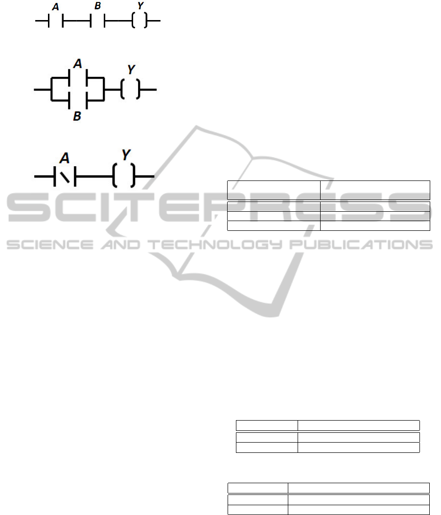
Figure 1: The ladder diagram AND gate.
Figure 2: The ladder diagram OR gate.
Figure 3: The ladder diagram NOT gate.
• AND: The coil is on (Y = 1) if and only if both
contacts are on. It is satisfied if A = 1 and B = 1.
Otherwise, the coil is off.
• OR: The coil is on (Y = 1) if at least one contact
is on. It is satisfied if A = 1 or B = 1. Otherwise,
the coil is off.
• NOT: The coil is on (Y = 1) if a contact is on.
A = 0 causes the contact to be switched on. The
coil is off (Y = 0) if a contact is off. A = 1 causes
the contact to be switched off.
Using structers of basic logic gates we can build,
in ladder diagrams, more complex digital systems.
Now, it is out of scope of this paper. We will con-
sider this problem in the future.
4 LOGIC CIRCUITS BASED ON
PHYSARUM POLYCEPHALUM
PROPAGATION
Ladder diagrams implement an idea of flowing power
from left to right. The output for the rung in the lad-
der diagram occurs on the extreme right side of the
rung and power is assumed to flow from left to right
if and only if there exists at least one closed path from
left to right making the flow possible. We apply this
idea to build logic gates in Physarum polycephalum
machines. Flowing power is replaced with propaga-
tion of plasmodium of Physarum polycephalum. Plas-
modium propagation is stimulated by attractants and
repellents (see Section 2). In our approach, stimuli
(attractants and repellents) are treated as data nodes.
We assume that plasmodium must occur in a proper
region to be influenced by a given stimulus. This re-
gion is determined by the radius depending on the in-
tensity of the stimulus. Using the analogy to flow-
ing power in rungs of ladder diagrams, we can build
logic gates in Physarum polycephalum machines by
the proper geometrical distribution of stimuli (attrac-
tants and repellents) on the substrate. Controlling the
power flow in rungs by opening/closing contacts is
replaced with controlling the plasmodium propaga-
tion by activating/deactivating stimuli. Relationships
between elements of ladder diagrams and stimuli of
Physarum polycephalum computing are collected in
Table 2.
Table 2: Relationships between elements of ladder dia-
grams and stimuli of Physarum polycephalum computing.
Ladder diagram element Physarum polycephalum
computing stimulus
Normally open contact Attractant controlled by input
Normally closed contact Repellent controlled by input
Coil Attractant controlling output
Table 3 shows interpretation of logic values (0 and
1) for inputs in terms of states of stimuli. Input val-
ues cause activation/deactivation of stimuli. Value 1
activates the stimuli whereas value 0 deactivates the
stimuli. Analogously, Table 4 shows interpretation of
logic values (0 and 1) for outputs in terms of states
of stimuli. In our approach, the output represented by
the coil in ladder diagrams is replaced with the attrac-
tant. We assume that the output attractant is always
activated. If plasmodium is attracted by it and occu-
pies it, then we interpret this state as 1. Otherwise, if
there is no plasmodium occupying the attractant, i.e.,
plasmodium is not attracted, the state is interpreted as
0.
Table 3: Representation of input logic values.
Boolean value Representation
0 Attractant/repellent deactivated
1 Attractant/repellent activated
Table 4: Representation of output logic values
Boolean value Representation
0 Absence of Physarum at the attractant
1 Presence of Physarum at the attractant
Our idea of paths of plasmodium propagation is
further presented graphically. In Table 5, we have col-
lected symbols used by us in diagrams.
As it was mentioned earlier, the idea of ladder dia-
grams has been applied in our logic gates constructed
in Physarum polycephalum machines. Figure 4 shows
distribution of stimuli for the AND gate. This distri-
bution simulates a serial connection of contacts. Plas-
TowardsLogicCircuitsbasedonPhysarumPolycephalumMachines-TheLadderDiagramApproach
167
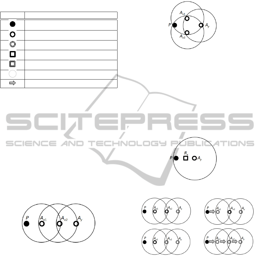
Table 5: Symbols of elements used in figures.
Symbol Meaning
Physarum
Attractant deactivated
Attractant activated
Repellent deactivated
Repellent activated
Region of influence
Direction of plasmodium propagation
modium of Physarum polycephalum P can be prop-
agated to the output attractant A
y
if and only if both
attractants A
x1
and A
x2
are activated. First, plasmod-
ium is attracted to A
x1
(because it is placed only in
its region of influence). After the achievement of this
goal, it is in the region of influence of A
x2
and it is
attracted by it. The achievement of A
x2
causes that
plasmodium is in the region of influence of A
y
and it
is attracted by it. Finally, plasmodium achieves A
y
. It
is interpreted as a logic output with value 1. Deacti-
vation of either the attractant A
x1
or A
x2
causes that
the path of propagation becomes broken, i.e., there
is a place where plasmodium is not attracted by any
attractant. Figure 7 shows paths of plasmodium prop-
agation for all possible combinations of input values
for A
x1
and A
x2
.
Figure 4: The Physarum AND gate.
Figure 5 shows distribution of stimuli for the OR
gate. This distribution simulates a parallel connection
of contacts. Plasmodium of Physarum polycephalum
P can be propagated to the output attractant A
y
if
one of the attractants A
x1
or A
x2
is activated. First,
plasmodium is attracted to A
x1
or A
x2
(because it is
placed in regions of influences). After the achieve-
ment of one or both of them, it is in the region of
influence of A
y
and it is attracted by it. Finally, plas-
modium achieves A
y
. It is interpreted as a logic output
with value 1. Deactivation of both attractants A
x1
and
A
x2
causes that the path of propagation becomes bro-
ken, i.e., plasmodium is not attracted by any attrac-
tant and cannot start from the initial position. Figure
8 shows paths of plasmodium propagation for all pos-
Figure 5: The Physarum OR gate.
sible combinations of input values for A
x1
and A
x2
.
The NOT gate behavior is simulated by the repel-
lent as it is shown in Figure 6. If the repellent R
x
is
activated (i.e., the input value is 1), then it avoids plas-
modium to be attracted by the output attractant A
y
.
Therefore, Physarum is not present at A
y
, i.e., the out-
put value is 0. Otherwise, plasmodium is not avoided
and achieves A
y
. Figure 9 shows paths of plasmod-
ium propagation for all possible combinations of in-
put values for R
x
.
Figure 6: The Physarum NOT gate.
a) b)
c) d)
Figure 7: States of the AND gate for all input combinations.
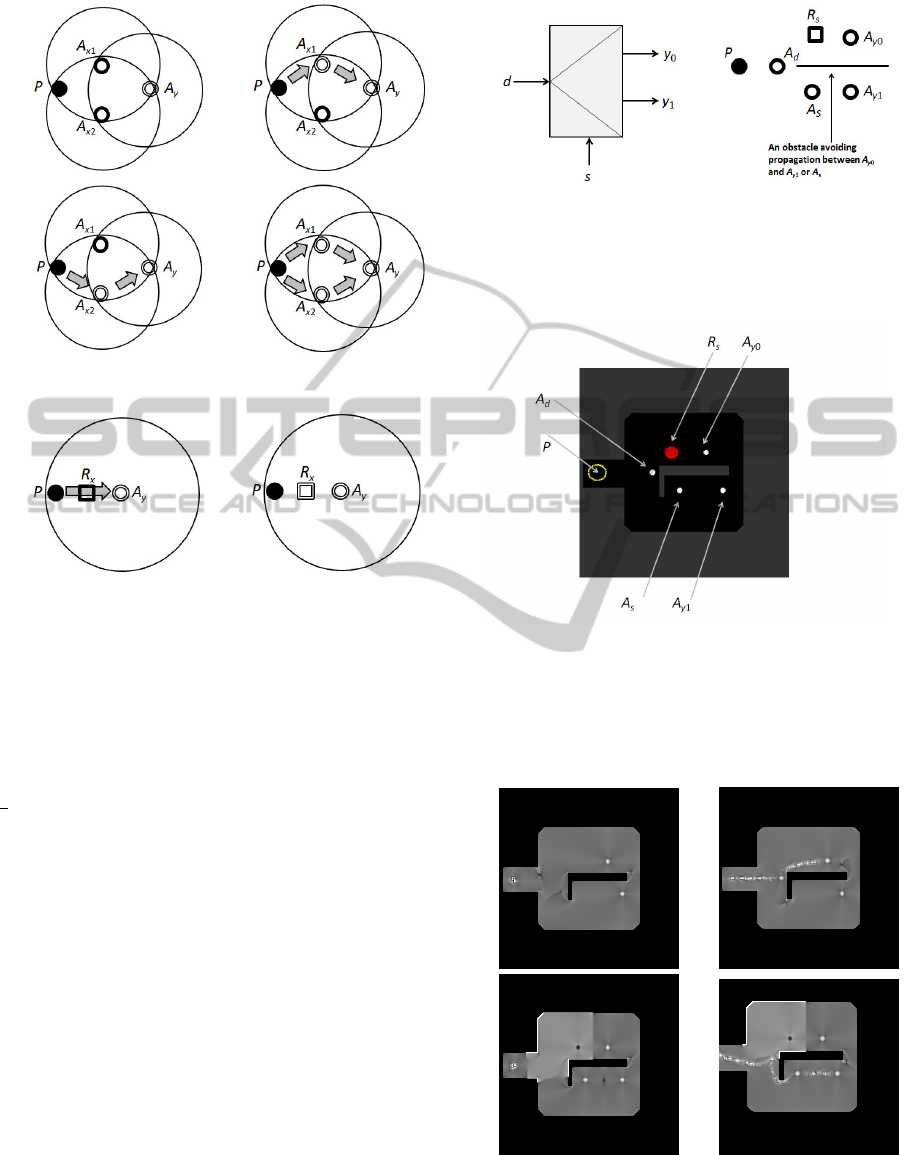
5 EXPERIMENT
In the experiment, we have built a Physarum poly-
cephalum demultiplexer based on the ladder diagram
structure. A demultiplexer is a device taking a single
input signal and selecting one of many data-output-
lines, which is connected to the single input. In Figure
10, a schematic symbol of the 1-to-2 demultiplexer
(a) and its implementation (b) using a particle model
of Physarum polycephalum (Jones and Adamatzky,
2010) are shown. In the schematic symbol: d is a
BIODEVICES2014-InternationalConferenceonBiomedicalElectronicsandDevices
168
a) b)
c) d)
Figure 8: States of the OR gate for all input combinations.
a) b)
Figure 9: States of the NOT gate for all input combinations.
data input, s is a select input, and y
0
, y
1
are outputs.
The operation of the demultiplexer can be described
as follows:
• if s = 0, then y
0
= d,
• if s = 1, then y
1
= d.
The functional specification can be written as y
0
=
sd and y
1
= sd. In the Physarum polycephalum
implementation of the demultiplexer, one can see:
Physarum polycephalum (P), attractants (A
d
, A
s
, A
y0
,
A
y1
), repellent (R
s
). Let ROI denote the region of in-
fluence. For the topological distribution of Physarum
polycephalum, attractants and repellents, we assume
that:
• P belongs to ROI(A
d
),
• A
d
belongs to ROI(A
y0
), ROI(R
s
), and ROI(A
s
),
• A
s
belongs to ROI(A
y1
).
Logical states are implemented in the following way:
• s = 0 means R
s
and A
s
are deactivated, s = 1
means R
s
and A
s
are activated,
• d = 0 means A
d
is deactivated, d = 1 means A
d
is
activated.
It is worth noting that A
y0
and A
y1
are always acti-
vated.
a) b)
Figure 10: 1-to-2 demultiplexer: (a) a schematic symbol,
(b) distribution of stimuli.
In Figure 11, the experimental environment for a
particle model of Physarum polycephalum is shown.
Figure 11: The experimental environment for a particle
model of Physarum polycephalum.
In Figure 12, results of experiments are pre-
sented. Pictures taken by us show how Physarum
polycephalum was propagated in each situation.
a) b)
c) d)
Figure 12: Results of experiments: (a) for s = 0 and d = 0,
(b) for s = 0 and d = 1, (c) for s = 1 and d = 0, (d) for s = 1
and d = 1.
TowardsLogicCircuitsbasedonPhysarumPolycephalumMachines-TheLadderDiagramApproach
169

One can see the following cases:
• s = 0 and d = 0: uneventful, because there is no
data regardless of switch position,
• s = 0 and d = 1: no repellent causes the stream to
go to A
y0
, the model does not grow down because
it is outside the region of influence of A
y1
,
• s = 1 and d = 0: uneventful, because there is no
data regardless of switch position,
• s = 1 and d = 1: the repellent causes selection of
the lower path to A
y1
.
It means that the Physarum polycephalum behaves as
intended.
6 SUMMATION
In the paper, we have shown how to construct ba-
sic logic gates in Physarum polycephalum machines
using the idea of ladder diagrams. Proper relation-
ships between ladder diagrams and Physarum poly-
cephalum computing have been pointed out. The pa-
per consists, in the first step, in research connected
to developing a biological architecture of different
abstract digital devices based on the ladder diagram
principle. This principle is very popular in program-
ming Programmable Logic Controllers (PLCs). How-
ever, in case of PLCs, the ladder diagram principle is
used only at the abstract level as a high-level program-
ming language. The program is executed by silicon
microprocessors based on the standard architectures
not reflected in the direct flow of power. Our approach
could allow a direct hardware implementation of this
principle in different controllers. In our case, it is a
biological hardware implementation.
The approach presented in this paper may be used
in different constructions of logic gates in chemical
media or on biological substrates which are based on
the flow or propagation of some medium. An impor-
tant thing is to find the mechanism of controlling the
flow or propagation in the restricted regions by some
elements which can be activated or deactivated. The
main problem for the further work is to search for
mechanisms of constructing complex digital systems.
For example, in ladder diagrams, negations of com-
plex expressions must be realized using some internal
variables enabling us to carry states of coils to states
of contacts.
Another task for the further work is to implement
the presented idea in the experimental environment
for more complex circuits. In this case, an important
thing is the proper control over states of stimuli, i.e.,
their rapid activation or deactivation. Moreover, the
construction requires adjusting proper regions of in-
fluences of individual stimuli to model serial or paral-
lel connections.
ACKNOWLEDGEMENTS
This research is being fulfilled by the support of FP7-
ICT-2011-8.
REFERENCES
Adamatzky, A. (2010). Physarum Machines: Computers
from Slime Mould. World Scientific.
Adamatzky, A. and De Lacy Costello, B. (2002). Experi-
mental logical gates in a reaction-diffusion medium:
The xor gate and beyond. Physical Review E,
66:046112.
Adamatzky, A., Erokhin, V., Grube, M., Schubert, T., and
Schumann, A. (2012). Physarum chip project: Grow-
ing computers from slime mould. International Jour-
nal of Unconventional Computing, 8(4):319–323.
G
´
orecki, J., G
´
orecka, J., and Igarashi, Y. (2009). Infor-
mation processing with structured excitable medium.
Natural Computing, 8(3):473–492.
Jones, J. and Adamatzky, A. (2010). Towards physarum
binary adders. Biosystems, 101(1):51–58.
Motoike, I. N. and Yoshikawa, K. (2003). Information op-
erations with multiple pulses on an excitable field.
Chaos, Solitons & Fractals, 17(23):455 – 461.
Nakagaki, T., Yamada, H., and Toth, A. (2000). Maze-
solving by an amoeboid organism. Nature, 407:470–
470.
Rosandich, R. G. (1999). Fundamentals of Ladder Dia-
grams Programming. EC&M Books.
Schumann, A. and Pancerz, K. (2013). Towards an object-
oriented programming language for physarum poly-
cephalum computing. In Szczuka, M., Czaja, L.,
and Kacprzak, M., editors, Proceedings of the Work-
shop on Concurrency, Specification and Programming
(CS&P’2013), pages 389–397, Warsaw, Poland.
Sielewiesiuk, J. and G
´
orecki, J. (2001). Logical functions
of a cross junction of excitable chemical media. The
Journal of Physical Chemistry A, 105(35):8189–8195.
Steinbock, O., Kettunen, P., and Showalter, K. (1996).
Chemical wave logic gates. The Journal of Physical
Chemistry, 100(49):18970–18975.
BIODEVICES2014-InternationalConferenceonBiomedicalElectronicsandDevices
170
