
Iris: An Inter-cloud Resource Integration System for Elastic Cloud Data
Centers
Ryousei Takano, Atsuko Takefusa, Hidemoto Nakada, Seiya Yanagita and Tomohiro Kudoh
Information Technology Research Institute, National Institute of Advanced Industrial Science and Technology (AIST),
Central 2, 1-1-1 Umezono, Tsukuba, Ibaraki 305-8568, Japan
Keywords:
Inter-cloud, Virtual Infrastructure, Hardware as a Service, Nested Virtualization, Software Defined Network.
Abstract:
This paper proposes a new cloud computing service model, Hardware as a Service (HaaS), that is based on
the idea of implementing “elastic data centers” that provide a data center administrator with resources located
at different data centers as demand requires. To demonstrate the feasibility of the proposed model, we have
developed what we call an Inter-cloud Resource Integration System (Iris) by using nested virtualization and
OpenFlow technologies. Iris dynamically configures and provides a virtual infrastructure over inter-cloud
resources, on which an IaaS cloud can run. Using Iris, we have confirmed an IaaS cloud can seamlessly
extend and manage resources over multiple data centers. The experimental results on an emulated inter-cloud
environment show that the overheads of the HaaS layer are acceptable when the network latency is less than
10 ms. In addition, we reveal the large overhead from nested virtualization and show positive prospect for this
problem. We believe these results provide new insight to help establish inter-cloud computing.
1 INTRODUCTION
The inter-cloud paradigm provides a new perspective
on computing services by connecting distributed data
centers through high-speed networks. It is also an at-
tractive infrastructure for big data processing, disaster
recovery, and highly available applications. However,
an optimal approach to how cloud providers federate
distribute resources to construct a virtual infrastruc-
ture over distributed inter-cloud resources is not well
understood.
This paper focuses on inter-cloud federation
among Infrastructure as a Service (IaaS) clouds. IaaS
provides isolated sets of resources, including com-
puters, storage, and networks, with multiple users.
Typical IaaS clouds are managed by an IaaS plat-
form middleware, including OpenStack and Cloud-
Stack. IaaS may require large amounts of resources
as necessary, however the capacity of physical re-
sources in a single data center is limited. The inter-
cloud federation is a most promising solution for this
problem. Some researcher has proposed inter-cloud
architectures to facilitate cloud federation and inter-
operability (Buyya et al., 2010; Demchenko et al.,
2012). Some academic and industrial groups have
been standardizing a service model, a protocol, and
an interface such as the Open Cloud Computing In-
terface (Nyren et al., 2011), the Cloud Data Man-
agement Interface (SNIA, 2012), and the Open Vir-
tualization Format (DMTF, 2013). However, a single
standard has not yet found wide-spread acceptance
because standardization takes a long time to imple-
ment on most of IaaS platforms.
This paper proposes a novel inter-cloud service
model called Hardware as a Service (HaaS), which
enables us to implement “elastic data centers.” The
term HaaS was originally introduced in 2006 (Carr,
2006), but now it has been superseded by IaaS. We
have redefined the term HaaS as “on-demand provi-
sioning of resources for IaaS providers” in this paper.
In contrast to an IaaS model, our HaaS model tar-
gets on building a virtual infrastructure among mul-
tiple data centers. This means that a HaaS provider is
a resource broker for data center administrators, i.e.,
IaaS providers. While an existing federation service
of IaaS clouds introduces a new administrative inter-
face, a HaaS service allows an IaaS provider to seam-
lessly manage resources over an inter-cloud environ-
ment with an IaaS administrative interface.
To confirm the feasibility, we have developed Iris,
an inter-cloud resource integration system. Iris con-
structs a set of virtual resources over physical re-
sources by using nested virtualization and OpenFlow
technologies, and connections between the assembled
103
Takano R., Takefusa A., Nakada H., Yanagita S. and Kudoh T..
Iris: An Inter-cloud Resource Integration System for Elastic Cloud Data Centers.
DOI: 10.5220/0004850701030111
In Proceedings of the 4th International Conference on Cloud Computing and Services Science (CLOSER-2014), pages 103-111
ISBN: 978-989-758-019-2
Copyright
c
2014 SCITEPRESS (Science and Technology Publications, Lda.)
resources and the IaaS data center. Using Iris, we
have demonstrated CloudStack can seamlessly man-
age resources over multiple data centers on an em-
ulated inter-cloud environment. The experimental re-
sults show that the overheads of the HaaS layer are ac-
ceptable when the network latency is less than 10 ms.
Nested virtualization remains a costly solution today;
nevertheless it is fascinating because it allows flexi-
ble operation of inter-cloud resources. Both hardware
and software improvements for nested virtualization
will lead to resolve this problem in the near future as
the overhad of virtualization has been dramatically re-
duced by full virualization.
The rest of the paper is organized as follows. Sec-
tion 2 describes the background of inter-cloud re-
source management and proposes our HaaS model.
The design of a HaaS system is presented in Section 3,
followed by the implementation in Section 4. Sec-
tion 5 shows the experimental results, and we discuss
the feasibility of our HaaS model in Section 6. Fi-
nally, Section 7 summarizes the paper.
2 INTER-CLOUD RESOURCE
MANAGEMENT MODELS
Inter-cloud resource management is intended to con-
struct a Virtual Infrastructure (VI) in such a way that
providers can efficiently utilize resources over dis-
tributed data centers. A VI is an isolated set of re-
sources, including computers, storage, and networks.
Each data center is operated by utilizing a resource
management middleware suite, i.e., a Cloud OS, such
as CloudStack or OpenStack. Each cloud OS, how-
ever, provides users with services in a variety of dif-
ferent manners, and there is no commonly agreed
standard interface.
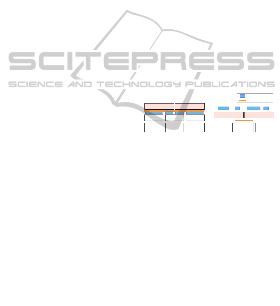
From the viewpoint of constructing a VI over
inter-cloud resources, we define two resource man-
agement models: an overlay model and an extension
model, as shown in Figure 1. In other words, the over-
lay model is a virtual Infrastructure as a Service (vI-
aaS) model; and the extension model is a Hardware
as a Service (HaaS) model. We categorize existing
inter-cloud solutions as a vIaaS model, and we pro-
pose a HaaS model in this paper.
The key to both is the federation layer and the in-
terface. By introducing a federation layer, abstrac-
tion of underlying resources is achieved. vIaaS bun-
dles several resource sets provided by IaaS clouds into
a single VI. For instance, RightScale
1
offers federa-
tion of IaaS clouds in such a way that it serves as a
1
http://www.rightscale.com/
glue layer among independently developed cloud in-
terfaces. Moreover, some cloud OSs provides a Vir-
tual Private Network (VPN) feature to connect an on-
premise data center with a public cloud. This is a
popular solution to implement a hybrid cloud, and
it is one form of vIaaS model. On the other hand,
HaaS provides IaaS clouds with isolated resources,
and an IaaS cloud can run on each VI distributed over
data centers. Each VI can transparently scale in and
out without concern for the boundary of data centers.
HaaS does not depend on a specific IaaS, and HaaS
can provide services with multiple and heterogeneous
IaaS clouds. While a vIaaS model has to introduce
a new administrative interface for the operation of a
VI, a HaaS model allows an IaaS provider to seam-
lessly manage resources over an inter-cloud environ-
ment with a Cloud OS interface. A Cloud OS, which
each requester uses in their own data center, can man-
age the provided remote resources in a provider data
center as if they were located in the requester’s data
center. We focus on the HaaS model in the rest of the
paper.
DC DC DC
IaaS
VI
IaaS IaaS
DC'
(requester)
DC'
(provider)
DC'
(requester)
VI
VI'(='IaaS) VI'(='IaaS)
(a) vIaaS: overlay model (b) HaaS: extension model
federation layer
'
IaaS tenant
'
'
'
'
'
'
'
'
'
'
'
'
'
'
'
'
'
'
'
'
'
'
Figure 1: Inter-cloud resource management models: the
relationship between Virtual Infrastructures, IaaS systems,
and data centers.
3 DESIGN
This section introduces Iris, a system for implement-
ing our HaaS model.
3.1 Overview
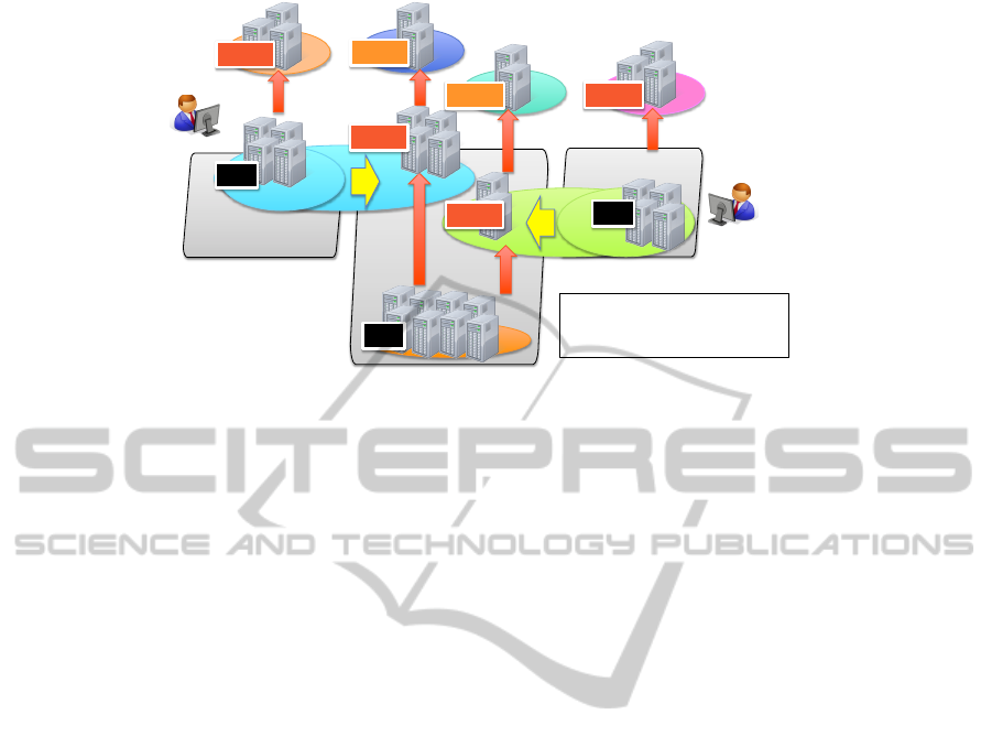
Figure 2 shows the overview of a HaaS system, which
enables IaaS clouds to extend over the HaaS layer in
a HaaS data center. A Cloud OS runs on each VI over
inter-cloud resources. This system works as follows:
1) an IaaS administrator detects an indication of ser-
vice degradation due to excessive access from IaaS
users; 2) the IaaS administrator requests additional re-
sources from a HaaS system; 3) to construct a VI, the
HaaS system allocates and isolates resources in the
HaaS data center, and it extends the layer 2 network
from the IaaS data center; 4) the size of the VI can be
elastically changed as needed.
CLOSER2014-4thInternationalConferenceonCloudComputingandServicesScience
104
HaaS$Data$Center
IaaS$DC$1$
IaaS$DC$2$
L
2
$VMs
L
1
$VMs
IaaSadmin
IaaStenant
IaaStenant
PMs
L
1
$VMs
L
1
$VMs
PMs:$Physical$Machines$
L
1
$VMs:$Level$1$Virtual$Machines$
L
2
$VMs:$Level$2$Virtual$Machines
L
2
$VMs
IaaStenant
L
1
$VMs
IaaStenant
IaaSadmin
PMs
OpenStack$
!"#$%&'&()%(&'*$%&(
)+',(-.(/-0,12$3(
.%4,$51,2612,'7(
PMs
CloudStack$
Figure 2: Elastic data center based on a HaaS system.
3.2 Requirements
The main requirements for implementing a HaaS sys-
tem are described as follows:
Ease of Use. To make IaaS providers widely accept
this service, the system must be easy to install on
existing IaaS systems. Any Cloud OS must be
able to handle HaaS resources as well as IaaS re-
sources, and then the Cloud OS must be able to
run on a VI without any modifications.
Secure Isolation. The system should establish se-
cure isolation between HaaS and IaaS systems to
avoid security incidents in a HaaS data center. For
instance, a compute node has multiple network in-
terfaces, one for the data plane; another for the
control plane. The system should prohibit access
to the control plane network, which is used for
internal communications to control a HaaS data
center, from the IaaS system.
Multi-tenancy. The system should provide multi-
ple IaaS providers with the service. Each IaaS
provider can use the overlapped range of IP ad-
dresses and VLAN IDs. To do that, virtualization
of the data center network is required.
3.3 Resource Virtualization
To meet the above requirements, we have developed
our HaaS system and called it Iris, which stands for
an Inter-cloud Resource Integration System. Iris con-
sists of compute and network resource management
modules. The key mechanisms underlying Iris are
multi-level virtualization of compute and network re-
sources. Iris allows IaaS clouds to introduce a HaaS
service with minimum effort. The following sub sec-
tions introduce two key technologies: nested virtu-
alization and OpenFlow, and show the benefits for a
HaaS system.
3.3.1 Nested Virtualization
The system provides IaaS providers with an abstract
machine instead of a physical machine. Nested vir-
tualization, which enables multiple guest hypervisors
to run on a host hypervisor, is a quite useful technol-
ogy that provides a way to achieve the requirement.
Since Intel architectures only support single level vir-
tualization, a hypervisor needs to trap and emulate
VMX instructions, which is an extension instruc-
tion set for hardware-assisted virtualization. Popular
open source hypervisors, KVM and Xen, already sup-
port nested virtualization (Ben-Yehuda et al., 2010;
Williams et al., 2012). Virtage (Ueno et al., 2010) is
yet another proprietary hypervisor on the Intel archi-
tecture. Virtage allows to provide a logical partition,
commonly called an LPAR, which is a subset of hard-
ware resources, on the Intel architecture. This LPAR
technology is essentially the same as a virtual ma-
chine (VM) technology. Virtage also supports nested
virtualization, and it is called “KVM on LPAR.”
The physical machine, single-level VM, and
second-level VM are shortened to PM (L
0
VM), L
1
VM, and L
2
VM, respectively. As shown in Figure 2,
each data center is comprised of PMs. IaaS provides
their users with a set of L
1
VMs. On the other hand,
HaaS provides IaaS with L
1
VMs, which belong to an
isolated layer 2 network, and unifies the networks for
an IaaS data center. IaaS can handle these L
1
VMs in
the same way as their own PMs. Therefore, a Cloud
OS works on a VI without modification. Notice that,
Iris:AnInter-cloudResourceIntegrationSystemforElasticCloudDataCenters
105

in contrast to existing IaaS clouds, some IaaS users
are offered L
2
VMs that physically run in a HaaS data
center. Such a VI dynamically expands and shrinks as
an IaaS administrator requires.
3.3.2 Network Virtualization
The aims of network virtualization are an extension of
a layer 2 network between data centers and support of
multi-tenancy. In other words, each VI belongs a iso-
lated and flat layer 2 network. To achieve these goals,
first, a HaaS system divides its network into several
isolated sub-networks for each IaaS by network vir-
tualization. Second a HaaS system connects the sub-
network with an IaaS data center network by layer 2
network extension. In addition, a HaaS system is re-
quired to support VM migration inside a VI over data
centers.
An IaaS data center requires only a gateway node
to connect a HaaS data center. Iris builds a full-mesh
overlay network for isolating each VI from the others,
using OpenFlow (McKeown et al., 2008) and layer 2
tunneling. We can use several layer 2 tunneling pro-
tocols, such as Generic Routing Encapsulation (GRE)
and VXLAN (Mahalingam et al., 2013). Moreover,
to extend a layer 2 network between data centers,
there are two options available, layer 2 tunneling and
dynamic network circuit provisioning, including OS-
CARS (Guok et al., 2008) and OGF Network Service
Interface (NSI) (Belter et al., 2013). Currently Iris
only supports the GRE protocol.
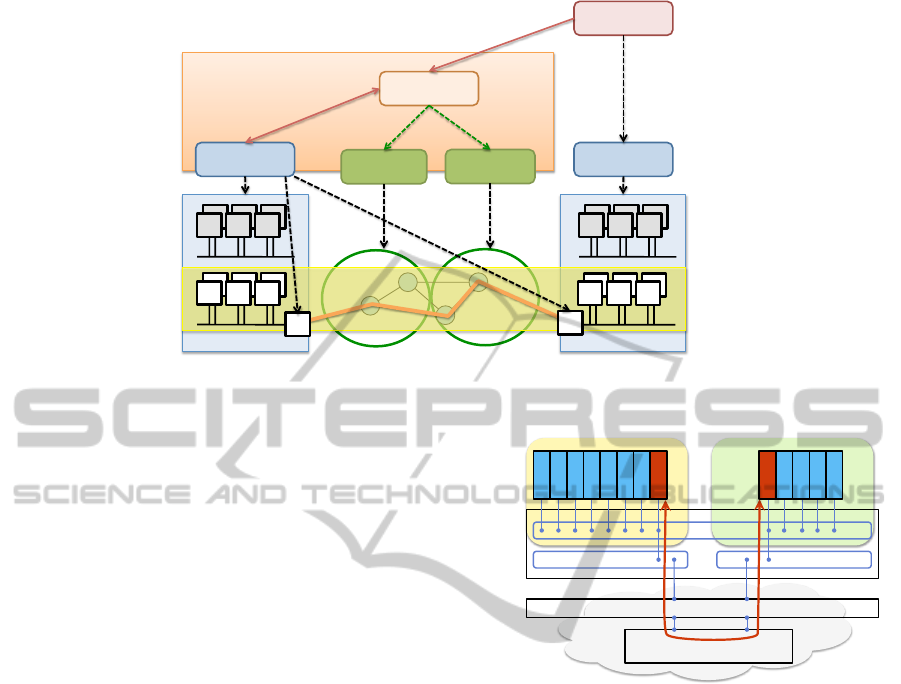
4 Implementation
We have been developing Iris on top of Gri-
dARS (Takefusa et al., 2011), as shown in Figure 3.
An IaaS administrator manages their data center using
a Cloud OS like CloudStack. Iris dynamically extends
and shrinks the scale of the data center as demand re-
quires.
GridARS is an Inter-cloud resource manage-
ment system, which provides performance-assured
resources over inter-cloud environments; and appro-
priate monitoring information for each user via a
Web services-based interface. GridARS consists of
a Resource Management System (RMS) and a Dis-
tributed Monitoring System (DMS), and this hierar-
chical architecture allows worldwide scaling. RMS
co-allocates various resources, such as computers and
storage in clouds and network connection between the
clouds by using common interfaces such as OGF NSI.
DMS automatically gathers distributed monitoring in-
formation from the allocated resources for each user
in cooperation with RMS.
Iris works as a data center RMS and interacts with
a GridARS resource coordinator via a Web services-
based interface. It manages the resources of a HaaS
data center and asociated gateway nodes. Iris is
comprised of three main components: a compute
controller, an OpenFlow switch, and an OpenFlow
controller. Open vSwitch (Pfaff et al., 2009) soft-
ware switches run on all compute nodes and gateway
nodes. An OpenFlow controller, Iris controller, is im-
plemented based on the Floodlight controller
2
. Iris
controller keeps track of the membership and the net-
work topology of a VI. Such information is stored in
a management registry. The management registry in-
cludes a mapping table of MAC addresses and IP ad-
dresses like an ARP table. It is initialized from a given
configuration file when launching a VI.
The management registry should update appropri-
ately when a Cloud OS executes VM migration. Iris
controller detects VM migration and updates the man-
agement registry without explicit interaction with a
Cloud OS. An ARP request is sent to Iris controller by
a PacketIn mechanism. After that, it works as follows.
If the source MAC address of the ARP request is in-
side a HaaS data center, the management registry is
updated and then an ARP response packet is returned.
Otherwise, the ARP request is forwarded to an IaaS
data center via the gateway node. Moreover, a guest
OS sends RARP packets after the user VM migrates.
Iris controller receives an RARP packet, followed by
updating flow tables of Open vSwitches.
5 EXPERIMENTS
To demonstrate the feasibility of the proposed HaaS
system, we have conducted experiments using Iris on
an emulated inter-cloud environment. We have com-
pared the performance with a generally configured
IaaS system from the following three points of view:
the deployment time of a User VM (UVM); the mi-
gration time of a UVM; and the computing and I/O
processing performance on a UVM.
5.1 Experimental Settings
We used two experimental settings: AGC and HCC.
The former is an emulated inter-cloud environment,
which consists of two data centers. The latter is an
experimental testbed for evaluating nested virtualiza-
tion technologies.
2
http://www.projectfloodlight.org/floodlight/
CLOSER2014-4thInternationalConferenceonCloudComputingandServicesScience
106
GridARS
Network
management
Data$Center
Iris CloudStack
Resource
Coordinator
Virtual(Infrastructure
Requester
(IaaS admin)
Network
management
Data$Center
1. Request resources
2. Co-allocate
resources
GW
GW
Figure 3: Integration of Iris into the GridARS framework.
5.1.1 Setting 1: AGC
We used a 13 node-cluster, which is a part of the
AGC cluster. The cluster consists of Dell PowerEdge
M610 blade servers, and is comprised of 2 quad-core
Intel Xeon E5540/2.53GHz CPUs, 48 GB of mem-
ory, a 300 GB RAID1 SAS disk array, and a Broad-
com NetXtreme II 10 Gigabit Ethernet card. The Dell
M1000e blade enclosure holds 16 blade servers and a
24 port 10 Gigabit Ethernet switch. Hyper Threading
was disabled.
Figure 4 shows our emulated inter-cloud environ-
ment, where the above cluster is divided into two
sub-clusters, and both are connected through a net-
work emulator. The left hand side shows an IaaS data
center, which consists of seven compute nodes and
one gateway node. The Apache CloudStack version
4.0.2 was installed on these compute nodes. To iso-
late the private network, a VLAN ID was assigned to
each tenant, namely an IaaS user, from the range be-
tween 100 and 200. The right hand side shows a HaaS
data center, which consists of four compute nodes and
one gateway node. The two data centers communi-
cate with each other only via gateway nodes. Since
all nodes had a single network interface card (NIC),
the network configuration was set in such a way that
only the inter-data center traffic was forwarded to the
network emulator by using VLAN routing. To emu-
late a wide area network environment, we employed
GtrcNET-1 (Kodama et al., 2004), a hardware net-
work testbed that can control network latency up to
100 ms at wire rate. The MTU sizes of compute
nodes are set to 1500 bytes; the MTU sizes of the two
switches are set to 9000 bytes.
On the IaaS data center, the host OS was Ubuntu
12.04. On the HaaS data center, the host OS and L
1
!
!
"#$%&!
'(%!)*+,-./!
0(12!3$$4%$$
0(12!3 0(12!5
6&7&#!
'(5!)*+,-./!
8,9-2:;43!'<12!=>?@ABCD/
IaaS data center
HaaS data center
!
GW
GW
Bandwidth 1 Gbps
RTT: 0 – 200 msec
Figure 4: An emulated inter-cloud environment on AGC.
guest OS were Ubuntu 12.10 and Ubuntu 12.04, re-
spectively. On both data centers, CentOS 5.5 was
running on both IaaS and HaaS UVMs. The VM im-
ages were created using the qcow2 format. Live mi-
gration is required for the shared storage among the
source and destination nodes. In this experiment, an
NFS server ran on the IaaS data center. We used Open
vSwitch version 1.4.3 and Floodlight version 0.90.
Table 1 summarizes the specification of a UVM
environment. L
1
VM corresponds to an IaaS user VM
and a HaaS host VM; L
2
VM corresponds to a HaaS
user VM. In this experiment, a single L
1
VM ran on a
single L
0
physical machine, and a single L
2
VM also
ran on a single L
1
VM. Note that multiple VMs may
run on a single machine because CloudStack implic-
itly launches System VMs (SVMs), including a vir-
tual router and a console proxy.
5.1.2 Setting 2: HCC
We used two Hitachi BladeSymphony 2000 blade
servers, which consist of 2 octal-core Intel Xeon E5-
Iris:AnInter-cloudResourceIntegrationSystemforElasticCloudDataCenters
107
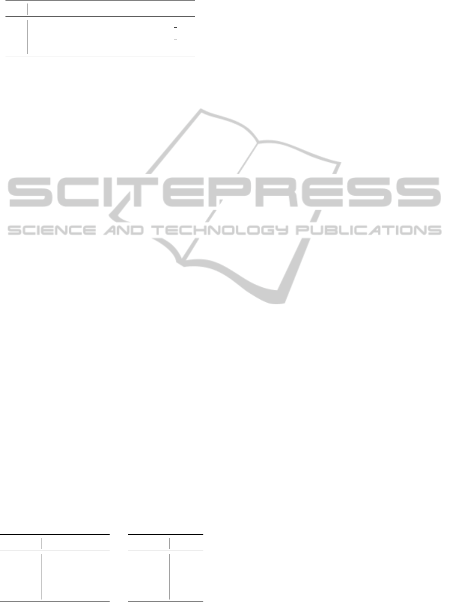
Table 1: Specification of a user VM on AGC.
CPU mem disk network
L
2
1 512 MB 5 GB virtio net
L
1
4 16 GB 32 GB virtio net
L
0
8 48 GB 300 GB bnx2x
2690/2.9 GHz CPUs, 64 GB of memory, Gigabit Eth-
ernet NICs, and 8 Gbps Fibre Channel HCAs. Hyper
Threading was enabled.
On this environment, we compared the perfor-
mance of two nested virtualization technologies:
KVM on Virtage and nested KVM. Virtage was in-
stalled to one server; Fedora 18 was installed on an-
other server. Virtage produces two LPARs, which
consist of 8 CPUs and 16 GB of memory, and directly
assigns a Gigabit Ethernet NIC and FC storage. Red
Hat Enterprise Linux 6.2 was running on the LPARs
or L
1
VM, and L
2
VM. Note that this environment is
only used in Section 5.4.1.
5.2 User VM Deployment
We have measured the elapsed time that it takes to de-
ploy a VM to IaaS or HaaS data centers. In this exper-
iment, a CloudStack user created a single availability
zone over two data centers. All VM images are lo-
cated on the primary storage, that is the NFS server in
an IaaS data center. Table 2a shows the deployment
times of a UVM, where the network latency varies
from 0 ms to 100 ms. The round trip time is double
the latency. Note that the inter-data center network is
not used for deployment inside an IaaS data center.
These numbers are obtained from CloudStack man-
agement server logs. They do not include the deploy-
ment time of CloudStack SVMs and the OS startup
time. The deployment time grows as the network la-
tency increases. This can be explained as follows. A
cloud agent on a compute node communicates with
the CloudStack managemnt server to generate a VM
configuration file. In the meantime multiple messages
are exchanged through an inter-data center network.
This makes a negative impact on the deployment time.
Table 2: Elapsed time of user VM deployment [seconds].
(a) one zone (b) two zones
IaaS HaaS
0 ms 11.88 11.89
5 ms - 15.19
10 ms - 18.84
100 ms - 86.50
HaaS
0 ms 31.02
5 ms 32.16
10 ms 33.45
100 ms 36.56
In the next experiment, we created two availabil-
ity zones. One zone is located in an IaaS data center;
the other zone is located in an HaaS data center. Each
zone has its own primary storage. Here we compare
two configurations: SVMs on HaaS and SVMs on
IaaS. The former is a configuration where SVMs are
running in a HaaS data center, and this is the default
behavior of CloudStack. The latter is a configuration
where SVMs are running in an IaaS data center. Ta-
ble 2b compares the UVM deployment time with two
availability zones. The result is larger and more uni-
form than that of Table 2a. This is mainly because of
the overhead of nested virtualization. While a UVM is
deploying, a virtual router works and communicates
with the management server to generate the network
configuration. In this case, a virtual router runs not
on an L
1
VM but on an L
2
VM. This problem can
be avoided by migrating a virtual router from a HaaS
data center to an IaaS data center. However, the out-
going traffic from a HaaS data center is routed via an
IaaS data center. This causes a decrease in the net-
work performance.
In addition, we have confirmed multi-tenancy, that
is, Iris enables us to provide resources even with mul-
tiple IaaS data centers. To do that, we divided an IaaS
data center into two 4-node data centers and set up
CloudStack in each data center. CloudStack assigns
VLAN IDs to each IaaS user. Even if the same VLAN
ID is assigned among different IaaS users, there is no
problem because Iris can completely isolate their net-
works by using OpenFlow.
5.3 User VM Migration
An IaaS administrator can migrate UVMs from a
compute node to another node. A HaaS system en-
ables us to migrate VMs between data centers us-
ing the same IaaS API, i.e., a CloudStack API called
migrateVirtualMachine. Shown in Figure 5 are the
data from the migratation time between an IaaS data
center and a HaaS data center. These numbers are ob-
tained from CloudStack management server logs.
The baseline is VM migration within IaaS data
center. In this case, the VM migration time is 2.62
ms. The migration times increases approximately lin-
early as the network latency increases. During VM
migration, the memory pages are copied over data
centers. Therefore, the migration time grows as the
network latency increases. Notice that VM migration
inside a HaaS data center is also affected by the net-
work latency. This is because compute nodes, i.e., L
1
VM, communicate with the management server via
the inter-data center network.
CLOSER2014-4thInternationalConferenceonCloudComputingandServicesScience
108
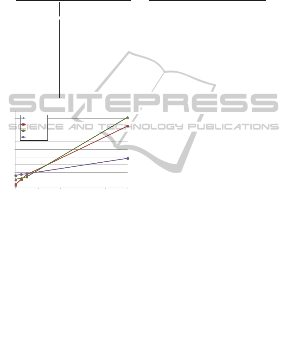
Table 3: Relative performance of the BYTE UNIX benchmark normalized to the physical machine on two settings [%]. The
performance of HaaS UVM (L
2
VM) on Virtage is mostly comparable to IaaS UVM (L
1
VM) on KVM.
(a) AGC (b) AIST + HCC
IaaS UVM HaaS UVM
dhrystone 77.16 57.07
whetstone 86.29 70.08
execl 157.00 4.71
file copy 256 48.93 37.75
file copy 1024 45.96 35.51
file copy 4096 56.87 43.01
pipe 49.02 38.49
context switch 205.67 9.43
spawn 256.80 4.82
shell 95.96 4.18
syscall 29.57 22.73
HaaS UVM HaaS UVM
(Virtage) (KVM)
dhrystone 47.27 48.82
whetstone 77.24 74.86
execl 62.44 4.31
file copy 256 125.71 125.00
file copy 1024 119.84 119.10
file copy 4096 113.65 98.05
pipe 128.23 119.91
context switch 1146.68 65.21
spawn 177.39 3.19
shell 71.99 4.71
syscall 165.04 159.55
0"
10"
20"
30"
40"
50"
60"
70"
80"
90"
100"
0" 20" 40" 60" 80" 100"
VM#migra)on#Time#[seconds]
Network#latency#[milliseconds]
IaaS"/>"IaaS"
IaaS"/>"HaaS"
HaaS"/>"IaaS"
HaaS"/>"HaaS"
Figure 5: Elapsed time of user VM migration between two
data centers.
5.4 User VM Performance
To evaluate the impact of nested virtualization, we
have measured the performance of UVMs on both an
IaaS cluster and a HaaS cluster.
5.4.1 BYTE UNIX Benchmark
The BYTE UNIX benchark
3
is a micro benchmark
suite for evaluating the performance of a UNIX-like
system. It includes the following benchmark pro-
grams: Dhrystone 2 using register variables (dhrys-
tone), Double-Precision Whetstone (whetstone), Ex-
ecl Throughput (execl), File Copy 256 bufsize 500
maxblocks (file copy 256), File Copy 1024 buf-
size 2000 maxblocks (file copy 1024), File Copy
4096 bufsize 8000 maxblocks (file copy 4096),
3
https://code.google.com/p/byte-unixbench/
Pipe Throughput (pipe), Pipe-based Context Switch-
ing (context switch), Process Creation (spawn), and
Shell Scripts (shell). Shown in Table 3 are the data
from the relative performance normalized to the phys-
ical machine.
With HaaS UVM in AGC, some tests, including
execl, spawn, context switch, and shell, significantly
degrade the performance, i.e, less than 10 %, com-
pared with the other tests, including compute and I/O
intensive programs. This is caused by a multiplica-
tion of VM exits. KVM on an L
1
VM (L
1
KVM)
traps and emulates VMX instructions executing on
an L
2
VM. To handle a single L
2
VM exit, L
1
KVM
performs many operations such as read and write of
the VMCS, disable interrupts, page table operations,
and so on. Eventually, a single L
2
VM exit causes
many L
1
VM exits. This is known as VM exit mul-
tiplication. We have confirmed the number of VM
exits increases from 64 to 70 times larger on a nested
VM environment. The analysis reason for VM exits
shows that the overhead of address space operations
grows significantly in a nested virtualization environ-
ment (Amontamavut et al., 2013).
The performance of compute intensive tests, such
as dhrystone and whetstone, is relatively low. In this
experiment, we could not use the optimal CPU con-
figuration because CloudStack deploys a VM with the
default QEMU64 CPU model. For instance, some
special instruction sets could not be used as they are in
the physical machine. Moreover, with IaaS UVM and
HaaS UVM (Virtage), the results of spawn and con-
text switch tests are not intuitive. The performance
of UVM is obviously better than that of the physical
node. This can be considered because the overhead of
synchronization is reduced due to the smaller number
Iris:AnInter-cloudResourceIntegrationSystemforElasticCloudDataCenters
109
of CPU cores.
The performance of L
2
VM on Virtage is mostly
comparable to L
1
VM on KVM. This means that a
HaaS UVM on Virtage can obtain the equivalent per-
formance of an IaaS UVM. KVM suffers from VM
exit multiplication. In contrast, Virtage reduces the
frequency of L
1
VM exits by virtualization of the Ex-
tended Page Table (EPT) using EPT shadowing.
5.4.2 Network Performance
We measured the effect of nested virtualization on the
network performance. In this experiment, we disabled
network offloading features, including generic seg-
mentation offload and generic receiver offload, as this
can improve network performance and reduce CPU
load, and because kernel panics occurred when these
features were enabled. As a result, the network good-
put between two physical compute nodes was limited
to under 4 Gbps.
Table 4 shows the round trip latency between two
UVMs by using the ping command. The network la-
tency increases three times due to the nested virtu-
alization. Comparing migration inside a data center
with migration between data centers, the latter in-
creases by two routing hops. This incurs extra la-
tency. Table 5 shows the network goodput between
two UVMs by using the Iperf command. The mes-
sage length is set to 32 KB. The goodput drops down
to 40 percent due to the nested virtualization. We will
discuss this issue in Section 6.
Table 4: Roundtrip latency between user VMs [ms].
src \dest IaaS UVM HaaS UVM
IaaS UVM 0.61 1.62
HaaS UVM 1.62 1.85
Table 5: Goodput between user VMs [Mbps].
src \dest IaaS UVM HaaS UVM
IaaS UVM 789 405
HaaS UVM 700 310
6 DISCUSSION
In this paper, we have employed a VM technology to
provide an L
1
VM. Another approach is OS-level vir-
tualization, such as Linux containers (LXC), Docker,
OpenVZ, and Linux VServer. For instance, Planet-
Lab (Bavier et al., 2004), which is a platform for
planetary-scale services, utilizes VServer to provide
an isolated resource container. OS-level virtualization
is a light-weight method compared to a VM, and the
overhead is negligible. In spite of the benefit, we fi-
nally decided to employ nested virtualization in terms
of isolation. We have met with some serious prob-
lems caused by LXC because containers are not per-
fectly isolated at the kernel level. For instance, an
NFS client and Open vSwitch could not run normally
when we used an LXC container as an L
1
VM. Al-
though an ad hoc workaround for each problem exists,
it is not sufficient.
The experimental results show that current nested
virtualization technology suffers from heavy VM exit
multiplication, resulting in large performance degra-
dation on an L
2
VM. This is because both the im-
plementation of KVM and the hardware support of
the CPU are still immature. Such barriers will be re-
solved in the near future. The latest Intel architecture
supports hardware-based VMCS shadowing; Virtage
supports software-based EPT shadowing. These fea-
tures allow us to significantly reduce the overhead of
nested virtualization, and it is certain that KVM will
support them. Therefore, we believe nested virtual-
ization is a promising solution to achieve flexible re-
source management.
Section 5.4.2 shows that nested virtualization in-
troduces large overhead on network performance. To
tackle this issue, VMM-bypass I/O technologies, in-
cluding PCI passthrough and SR-IOV, have been in-
troduced (Dong et al., 2012). We plan to use PCI
passthrough with a single-level as well as nested vir-
tualization to improve I/O performance on an L
2
VM.
How to handle the heterogeneous performance be-
tween L
1
VM and L
2
VM in context of QoS and SLA
is an open issue. An IaaS provider is able to choose
wheather he/she discloses the heterogeneity as an op-
erational policy. For instance, L
1
VM and L
2
VM can
be categorized into the different VM instance types.
7 CONCLUSION
Inter-cloud federation among heterogeneous systems
and/or organizations is a significant challenge. This
paper proposes a new cloud computing service model,
Hardware as a Service (HaaS), a service that dynam-
ically configures and provides virtual resources, on
which IaaS can run, by using nested virtualization and
OpenFlow. To demonstrate the feasibility of the pro-
posed model, we have developed Iris on top of the
GridARS inter-cloud resource management system.
Using Iris, we have confirmed that CloudStack can
seamlessly manage resources over multiple data cen-
CLOSER2014-4thInternationalConferenceonCloudComputingandServicesScience
110

ters on an emulated inter-cloud network. Iris is in-
dependent of the Cloud OS, and it is not limited to
working with any Cloud OSs, including OpenStack
and even proprietary software. The impact on the us-
ability is negligible when the network latency is less
than 10 ms. A 10 ms latency roughly corresponds to
1000 kilometers in actual networks, which covers the
major cities in Japan. However, nested virtualization
introduces a non-negligible overhead. But, since both
software and hardware improvements will lead to get-
ting rid of this issue, we believe nested virtualization
is a promising solution to achieving flexible resource
management like that provided by our HaaS model.
The evaluation is still limited and we need to con-
sider more realistic scenarios in terms of scalability
and workload. We also plan to explore use cases such
as IaaS migration for disaster recovery. Using Iris, an
entire IaaS can be migrated to a differently configured
data center.
ACKNOWLEDGEMENTS
This work was partly funded by the FEderated Test-
beds for Large-scale Infrastructure eXperiments (FE-
LIX) project of the National Institute of Information
and Communications Technology (NICT), Japan. We
would like to thank the Hitachi Harmonious Comput-
ing Center for conducting a performance evaluation of
nested virtualization technologies on their equipment.
REFERENCES
Amontamavut, P., Takano, R., and Hayakawa, E. (2013).
Performance evaluation of nested virtualization based
on KVM. In PRAGMA 24 students workshop.
Bavier, A., Bowman, M., Chun, B., Culler, D., Karlin, S.,
Muir, S., Peterson, L., Roscoe, T., Spalink, T., and
Wawrzoniak, M. (2004). Operating system support for
planetary-scale services. In Proc. of the First Sympo-
sium on Network Systems Design and Implementation
(NSDI).
Belter, B., Krzywania, R., Kudoh, T., and van Malenstein,
G. (2013). Federating SDN-enabled islands with an
extended NSI Framework. In Proc. of the TERENA
Networking Conference (TNC2013).
Ben-Yehuda, M., Day, M. D., Dubitzky, Z., Factor, M.,
Har’El, N., Gordon, A., Liguori, A., Wasserman, O.,
and Yassour, B.-A. (2010). The turtles project: design
and implementation of nested virtualization. In Proc.
of the 9th USENIX conference on Operating systems
design and implementation (OSDI), pages 1–6.
Buyya, R., Ranjan, R., and Calheiros, R. (2010). Intercloud:
Utility-oriented federation of cloud computing envi-
ronments for scaling of application services. In Proc.
of the 10th International Conference on Algorithms
and Architectures for Parallel Processing (ICA3PP),
pages 13–31.
Carr, N. (2006). Here comes HaaS. [online] http://
www.roughtype.com/?p=279.
Demchenko, Y., Ngo, C., Makkes, M., Stgrijkers, R., and
de Laat, C. (2012). Defining inter-cloud architecture
for interoperability and integration. In Proc. of the
IARIA Third International Conference on Cloud Com-
puting, GRIDs, and Virtualization, pages 174–180.
DMTF (2013). Open Virtualization Format Specifi-
cation. [online] http://www.dmtf.org/sites/default/
files/standards/documents/DSP0243 2.0.1.pdf.
Dong, Y., Yang, X., Li, J., Liao, G., Tian, K., and Guan,
H. (2012). High performance network virtualization
with sr-iov. Journal of Parallel Distributed Comput-
ing, 72(11):1471–1480.
Guok, C., Robertson, D., Thompson, E. C. M., Johnston,
W., and Tierney, B. (2008). A User Driven Dy-
namic Circuit Network Implementation. In Proc. of
the 3rd IFIP/IEEE Distributed Autonomous Network
Management Systems.
Kodama, Y., Kudoh, T., Takano, R., Sato, H., Tatebe, O.,
and Sekiguchi, S. (2004). GNET-1: Gigabit Ethernet
Network Testbed. In Proc. of the International Con-
ference on Cluster Computing, pages 185–192.
Mahalingam, M., Dutt, D., Duda, K., Agarwal, P., Kreeger,
L., Sridhar, T., Bursell, M., and Wright, C. (2013).
Vxlan: A framework for overlaying virtualized layer
2 networks over layer 3 networks. IETF Internet Draft
draftmahalingam-dutt-dcops-vxlan-01.txt.
McKeown, N., Anderson, T., Balakrishnan, H., Parulkar,
G., Peterson, L., Rexford, J., Shenker, S., and Turner,
J. (2008). OpenFlow: enabling innovation in campus
networks. SIGCOMM Computer Communication Re-
view, 38(2):69–74.
Nyren, R., Edmonds, A., Papaspyrou, A., and Metsch, T.
(2011). Open Cloud Computing Interface – Core. [on-
line] http://ogf.org/documents/GFD.183.pdf.
Pfaff, B., Pettit, J., Koponen, T., Amidon, K., Casado, M.,
and Shenker, S. (2009). Extending networking into
the virtualization layer. In 8th ACM Workshop on Hot
Topics in Networks (HotNets-VIII).
SNIA (2012). Cloud Data Management In-
terface (CDMI) Version 1.0.2. [online]
http://snia.org/sites/default/files/CDMI v1.0.2.pdf.
Takefusa, A., Nakada, H., Takano, R., Kudoh, T., and
Tanaka, Y. (2011). GridARS: A Grid Advanced
Resource Management System Framework for Inter-
cloud. In Proc. of the 1st International Workshop
on Network Infrastructure Services as part of Cloud
Computing (NetCloud).
Ueno, H., Hasegawa, S., and Hasegawa, T. (2010). Virtage:
Server Virtualization with Hardware Transparency. In
Proc. of Euro-Par 2009, pages 404–413.
Williams, D., Jamjoom, H., and Weatherspoon, H. (2012).
The Xen-Blanket: Virtualize Once, Run Everywhere.
In Proc. of the ACM European Conference on Com-
puter Systems (EuroSys).
Iris:AnInter-cloudResourceIntegrationSystemforElasticCloudDataCenters
111
