
Fuzzy-rule-embedded Reduction Image Construction Method
for Image Enlargement with High Magnification
Hakaru Tamukoh
1
, Noriaki Suetake
2
, Hideaki Kawano
3
, Ryosuke Kubota
4
, Byungki Cha
5
and Takashi Aso
5
1
Graduate School of Life Science and Systems Engineering, Kyushu Institute of Technology, Kyushu, Japan
2
Graduate School of Science and Engineering, Yamaguchi University, Yamaguchi, Japan
3
Graduate School of Engineering, Kyushu Institute of Technology, Kyushu, Japan
4
Department of Intelligent System Engineering, Ube National College of Technology, Ube, Japan
5
Faculty of Management and Information Sciences, Kyushu Institute of Information Sciences, Kyushu, Japan
Keywords:
Image Enlargement, Image Reduction, Data Embedding, Fuzzy Inference.
Abstract:
This paper proposes a fuzzy-rule-embedded reduction image construction method for image enlargement. A
fuzzy rule is generated by considering distribution of pixel value around a target pixel. The generated rule is
embedded into the target pixel in a reduction image. The embedded fuzzy rule is used in a fuzzy inference
to generate a highly magnified image from the reduction image. Experimental results, which scale factors
are three and four, show that the proposed method realizes high-quality image enlargement in terms of both
objective and subjective evaluations in comparison with conventional methods.
1 INTRODUCTION
In recent years, high-resolution displays have become
widely used such as high-definition televisions, mo-
bile devices and smart phones. In addition, a 4K
(3840×2160 pixels) resolution already exist in digi-
tal television and digital cinematography, and an 8K
(7680×4320 pixels) resolution will be available as
ultra-high-definition displays in the near future. At
the same time, people can obtain over giga-pixel
images, because high-resolution digital cameras are
widely commoditized. In addition, image- and video-
sharing services become as common all over the
world. To upload image or video to these services,
people have to reduce image size into less than quar-
ter size. Naturally, users require browsing high-
resolution images on the high-resolution displays. To
satisfy this requirement, whole or part of image have
to be enlarged larger than four times in size.
Image reduction and enlargement methods are
very important technologies in sharing and display-
ing images among such devices. Classical image
scaling methods—such as nearest neighbor interpo-
lation (NNI), bilinear interpolation (BLI), and bi-
cubic Interpolation (BCI)—are based on interpola-
tion using kernels (Lin, 1990), (Keys, 1981). These
interpolation-based methods achieve fast smooth im-
age reduction and enlargement; however, once images
are reduced by these methods, they cannot restore the
high-frequency image components lost in the reduc-
tion process, and therefore cannot preserve clearly the
step edges and peaks of an image. This is caused
by the fact that the high-frequencyimage components
beyond the Nyquist frequency cannot be restored us-
ing these simple kernel-based methods. If multiple
images are available, a high-resolution image can be
generated from a set of low-resolution images in the
same scene (Farsiu et al., 2004), but they cannot be
applied to stationary images. To address this prob-
lem, various advanced image enlargement methods
from the single image accompanying the estimation
of the high-frequencycomponent have been proposed
(Greenspan et al., 2000), (Siu and Hung, 2012). The
estimated high-frequency component is overlapped
with a blurred image generated by interpolation based
methods, to generate a high-quality image. However,
estimation of high-frequency component is difficult
when scale factor is over three or four.
In this paper, we propose a fuzzy-rule-embedded
image construction method to generate a reduction-
image in the image reduction process. The embedded
fuzzy rules are used in the proposed fuzzy inference to
generate an enlarged image with high magnification
in the image enlargement process. To show the effec-
tiveness of the proposed method, we compare results
of the proposed method with the conventional meth-
228
Tamukoh H., Suetake N., Kawano H., Kubota R., Cha B. and Aso T..
Fuzzy-rule-embedded Reduction Image Construction Method for Image Enlargement with High Magnification.
DOI: 10.5220/0004851802280233
In Proceedings of the 9th International Conference on Computer Vision Theory and Applications (VISAPP-2014), pages 228-233
ISBN: 978-989-758-003-1
Copyright
c
2014 SCITEPRESS (Science and Technology Publications, Lda.)
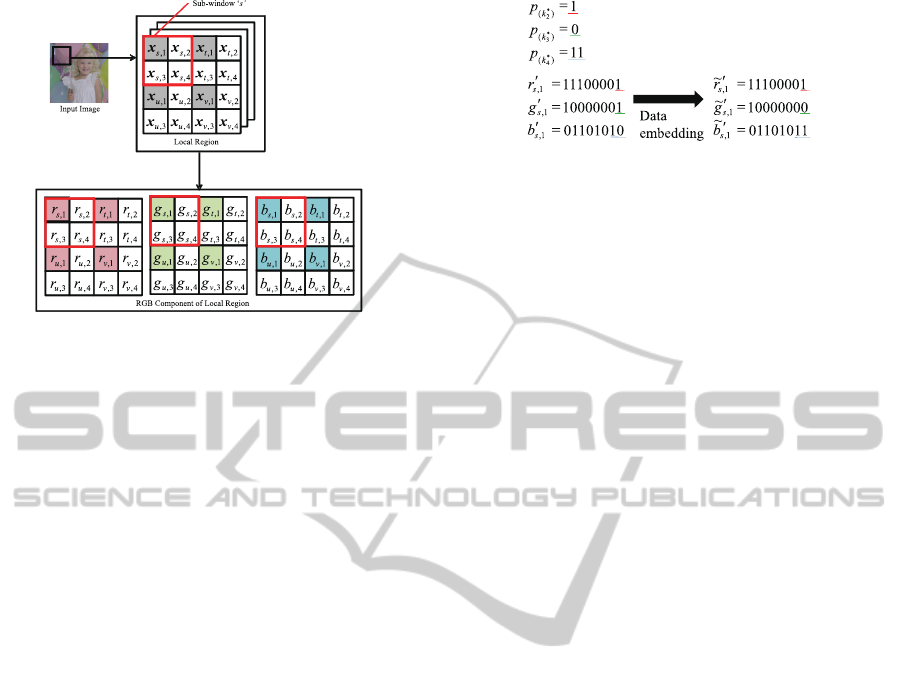
Figure 1: Definition of signals in this study.
ods under the subjective and objective evaluation.
2 FUNDAMENTAL METHOD
In this section, we explain a fundamental method
(Tamukoh et al., 2013) of a data embedding to intro-
duce an idea of proposed method easily.
Figure 1 shows a definition of signals for the pro-
posed method. The local region consists of 16 pixels
and they are divided into 4 sub-windows s,t,u, and v.
In the proposed method, the sub-window s is defined
as a focused window. Each sub-window has one ac-
tual pixel which is denoted by index ‘1’, and the other
3 pixels are interpolation target pixels which are de-
noted by index ‘2’, ‘3’ and ‘4’. Each pixel has 3 color
components r, g, and b, and each color component is
represented by 8 bit accuracy.
Both of an image reduction and an enlargement
process are based on NNI. If information on interpo-
lation target pixels can be embedded into the actual
pixel in the image reduction process, we can utilize
that information for high-quality enlargement in the
image enlargement process.
2.1 Image Reduction Process
In this subsection, we explain about an image reduc-
tion process and a data embedding method.
First, we select representative pixels k
∗
j
,( j =
2, 3, 4) for interpolation target pixels (~x
s,2
,~x
s,3
,~x
s,4
) in
the focused window. The k
∗
j
is calculated by Eq.(1).
k
∗
j
=
argmin
k∈(s,t)
k~x
k,1
−~x
s, j
k j = 2
argmin
k∈(s,u)
k~x
k,1
−~x
s, j
k j = 3
argmin
k∈(s,t,u,v)
k~x
k,1
−~x
s, j
k j = 4
. (1)
Figure 2: Data embedding scheme of fundamental method.
Then, a place code p
(k
∗
j
)
is calculated by following
equations based on the representative pixel k
∗
j
.
p
(k
∗
2
)
=
(
0 k
∗
2
= s
1 k
∗
2
= t
, (2)
p
(k
∗
3
)
=
(
0 k
∗
3
= s
1 k
∗
3
= u
, (3)
p
(k
∗
4
)
=
00 k
∗
4
= s
01 k
∗
4
= t
10 k
∗
4
= u
11 k
∗
4
= v
. (4)
Each code p
(k
∗
j
)
is represented as binary number.
Finally, the place code p
(k
∗
j
)
is embedded into
RGB component of the actual pixel ~x
s,1
. Figure
2 shows a data embedding scheme of fundamental
method. Each color component of actual pixel is rep-
resented as binary number r
′
s,1
,g
′
s,1
,b
′
s,1
. The place
code p
(k
∗
2
)
and p
(k
∗
3
)
are embedded into the lowest bit
of r
′
s,1
and g
′
s,1
component, respectively. Similarly, the
code p
(k
∗
4
)
is embedded into lower two bit of b
′
s,1
com-
ponent. By processing of the proposed data embed-
ding method, losses of R and G component on the ac-
tual pixel are one bit, and loss of B component is two
bit. However, these losses affect quite few changes to
the image, because the maximum error is up to three
in the range of 0 to 255 if lower two bit of the B com-
ponent is fully inversed.
After the data embedding, by the factor of 0.5 im-
age reduction is applied to the embedded image using
NNI, a data-embedded reduction image is obtained.
2.2 Image Enlargement Process
In this subsection, we explain about an image enlarge-
ment process and an interpolation scheme using the
data-embedded reduction image.
First, the local region of 2 × 2 pixels is extracted
from the data-embedded reduction image. Then, the
factor of two image enlargement is applied to the ex-
tracted pixels using NNI. The definition of signals
Fuzzy-rule-embeddedReductionImageConstructionMethodforImageEnlargementwithHighMagnification
229
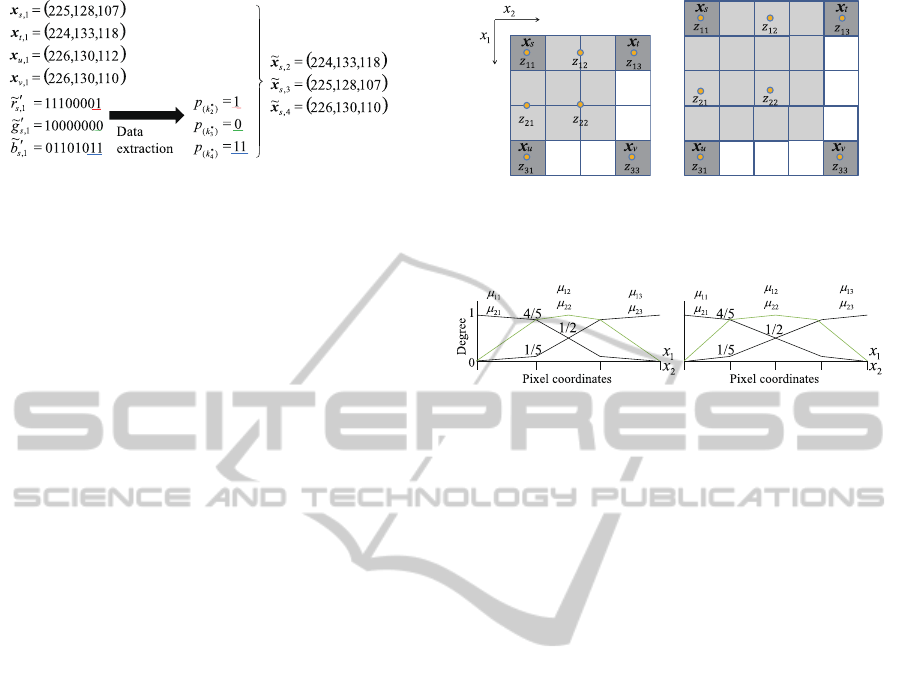
Figure 3: Interpolation scheme of fundamental method
based on the embedded information.
is also shown in Fig.1 as same as the image reduc-
tion process. In the enlargement process, white pix-
els in Fig.1 are defined as interpolation target pixels
(
˜
~x
s,2
,
˜
~x
s,3
,
˜
~x
s,4
).
Next, the embedded place code is extracted from
RGB components (r
s,1
,g
s,1
,b
s,1
) of actual pixel ~x
s,1
.
In particular, place codes p
(k
∗
2
)
, p
(k
∗
3
)
are extracted
from the lowest bit of r
′
s,1
,g
′
s,1
components, respec-
tively. Similarly, the place code p
(k
∗
4
)
is also extracted
from lower 2 bit of b
′
s,1
component.
Then, interpolation target pixels (
˜
~x
s,2
,
˜
~x
s,3
,
˜
~x
s,4
) are
interpolated by the following equations based on the
extracted place codes.
˜
~x
s,2
=
(
~x
s,1
p
(k
∗
2
)
= 0
~x
t,1
p
(k
∗
2
)
= 1
, (5)
˜
~x
s,3
=
(
~x
s,1
p
(k
∗
3
)
= 0
~x
u,1
p
(k
∗
3
)
= 1
, (6)
˜
~x
s,4
=
~x
s,1
p
(k
∗
4
)
= 00
~x
t,1
p
(k
∗
4
)
= 01
~x
u,1
p
(k
∗
4
)
= 10
~x
v,1
p
(k
∗
4
)
= 11
. (7)
Figure 3 shows a scheme of proposed interpolation
method. Interpolation target pixels (
˜
~x
s,2
,
˜
~x
s,3
,
˜
~x
s,4
)
copy the representative pixel to itself selected from
~x
s,1
,~x
t,1
,~x
u,1
,~x
v,1
based on the extracted place code
p
(k
∗
2
)
, p
(k
∗
3
)
and p
(k
∗
4
)
.
Finally, the lower 2 bit of B component changes
its value to “10”. This finalize process minimizes an
average error of data embedding effect.
The fundamental method directly copies the rep-
resentative pixel to the interpolation target pixel, thus,
it obtains better quality enlarged image than the ordi-
nary NNI. However, the fundamental method can be
applied to the factor of two only, and image artifact is
occasionally generated around edge region.
(factor = 3) (factor = 4)
Figure 4: Pixel coordinates and output values assignment
on fuzzy rules.
(factor = 3) (factor = 4)
Figure 5: Membership functions.
3 PROPOSED METHOD
In this section, we propose a fuzzy-rule-embedded re-
duction image construction method by extending the
fundamentalmethod. The basic idea of fuzzy rule em-
bedding is same as the data embedding of fundamen-
tal method. In the proposed method, we embed fuzzy
rules as data. The embedded fuzzy rules are used in
a fuzzy inference to generate an enlarged image with
high magnification.
We introduce a set of fuzzy rule for image enlarge-
ment as shown in Eq.8.
if x
1
is µ
11
and x
2
is µ
21
, then y is z
11
= ~x
s
,
if x
1
is µ
11
and x
2
is µ
22
, then y is z
12
,
if x
1
is µ
11
and x
2
is µ
23
, then y is z
13
= ~x
t
,
if x
1
is µ
12
and x
2
is µ
21
, then y is z
21
,
if x
1
is µ
12
and x
2
is µ
22
, then y is z
22
,
if x
1
is µ
13
and x
2
is µ
21
, then y is z
31
= ~x
u
,
if x
1
is µ
13
and x
2
is µ
23
, then y is z
33
= ~x
v
,
(8)
where, x
1
and x
2
represent pixel coordinates as shown
in Fig.4. Membership functions µ
ij
(i = 1, 2; j =
1, 2, 3) are defined in Fig.5. Output of fuzzy rules are
assigned as shown in Fig.4. Here, dark gray pixels are
given from the reduction image, and light gray pixels
are interpolation target in the enlargement process.
In the proposed fuzzy rules Eq.8, outputs z
11
, z
13
,
z
31
and z
33
can be assigned from the given pixel value.
On the other hands, rest of three outputs z
12
, z
21
and
z
22
should be calculated in the image reduction pro-
cess same as the fundamental method.
VISAPP2014-InternationalConferenceonComputerVisionTheoryandApplications
230

3.1 Image Reduction Process
Outputs of proposed fuzzy rules z
12
, z
21
and z
22
are
calculated by following eauation.
k
∗
z
12
k
∗
z
21
k
∗
z
22
=
argmin
k∈(0,1,2,3)
k~x
s
+
k
3
(~x
t
−~x
s
) − ψ
12
k
argmin
k∈(0,1,2,3)
k~x
s
+
k
3
(~x
u
−~x
s
) − ψ
21
k
argmin
k∈(0,1,2,3)
k~x
s
+
k
3
(~x
v
−~x
s
) − ψ
22
k
,
(9)
where, ψ
12
,ψ
21
, and ψ
22
represent virtual pixel val-
ues at pixel coordinates of z
12
, z
21
and z
22
. For in-
stance, ψ
22
is calculated by the average of around four
pixels at pixel coordinates of z
22
in the case of factor
three, and is directly copied from that of pixel value
in the case of factor four, shown in Fig.4.
After calculated Eq.9, a fuzzy rule code for em-
bedding is generated by following functions.
r
(k
z
12
)
=
00 k
∗
z
12
= 0
01 k
∗
z
12
= 1
10 k
∗
z
12
= 2
11 k
∗
z
12
= 3
, (10)
r
(k
z
21
)
=
00 k
∗
z
21
= 0
01 k
∗
z
21
= 1
10 k
∗
z
21
= 2
11 k
∗
z
21
= 3
, (11)
r
(k
z
22
)
=
00 k
∗
z
22
= 0
01 k
∗
z
22
= 1
10 k
∗
z
22
= 2
11 k
∗
z
22
= 3
. (12)
Each code is represented in two bit, and embedded
into lower two bit on RGB component of the actual
pixel~x
s
. After the fuzzy rule embedding, a fuzzy rule
embedded reduction image is obtained by using NNI
same as the fundamental method.
3.2 Image Enlargement Process
In the enlargement process, light gray pixels in Fig.4
are defined as interpolation target pixels. First, em-
bedded fuzzy rule codes are extracted from lower 2
bit of RGB components of the actual pixel~x
s
. Then,
outputs of the proposed fuzzy rules z
12
, z
21
and z
22
in
Eq.8 are calculated by the extracted fuzzy rule codes.
z
12
=
~x
s
r
(k
z
12
)
= 00
2
3
~x
s
+
1
3
~x
t
r
(k
z
12
)
= 01
1
3
~x
s
+
2
3
~x
t
r
(k
z
12
)
= 10
~x
t
r
(k
z
12
)
= 11
, (13)
z
21
=
~x
s
r
(k
z
21
)
= 00
2
3
~x
s
+
1
3
~x
u
r
(k
z
21
)
= 01
1
3
~x
s
+
2
3
~x
u
r
(k
z
21
)
= 10
~x
u
r
(k
z
21
)
= 11
, (14)
z
22
=
~x
s
r
(k
z
22
)
= 00
2
3
~x
s
+
1
3
~x
v
r
(k
z
22
)
= 01
1
3
~x
s
+
2
3
~x
v
r
(k
z
22
)
= 10
~x
v
r
(k
z
22
)
= 11
. (15)
After that, each interpolation target pixel value is cal-
culated by the proposed fuzzy rules using Sugeno-
Type fuzzy inference (Sugeno, 1985), (Takagi and
Sugeno, 1985). The firing strength is
w
i
= min(µ
1∗
(x
1
),µ
2∗
(x
2
)), (16)
where, µ
1,2∗
(·) (∗ = 1or2or3) are the membership
functions for first and second inputs in the proposed
fuzzy rule in Eq.8 and Fig.5. The interpolation target
pixel value is computed as the weighted average of all
rule outputs,
~x
target
=
7
∑
i=1
w
i
z
i
7
∑
i=1
w
i
, (17)
where, z
i
is the output of i-th rule in Eq.8 and it is
extracted from the embedded code. Finally, the lower
2 bit of R, G and B components change its value to
“10”, similar to the fundamental method.
4 EXPERIMENTAL RESULTS
To show the effectiveness and validity of the pro-
posed method, we compared the enlarged results of
the proposed method with three conventionalenlarge-
ment methods, NNI, BCI (Lin, 1990) and Nonlin-
ear Extrapolation method (NE) (Greenspan et al.,
2000). BCI and NE are selected as the most well-
known interpolation and high-frequency-component-
enhancement-based enlargement methods, respec-
tively. In our experiments, we use images (512×512
pixels) selected from the SIDBA database, which are
royalty-free and have been used in other computer
graphics performance tests, and are often referred to
as “standard images”.
4.1 Objective Evaluation
Error measures are used to objectively compare the
enlarged image with the original one, as shown in
Fuzzy-rule-embeddedReductionImageConstructionMethodforImageEnlargementwithHighMagnification
231
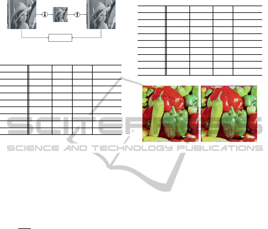
Decimation Enlargement
Comparator
(Error measure)
Figure 6: Error measurement for objective evaluation.
Table 1: Result of MSE evaluation (factor = 3)
NNI BCI NE Proposed
Airplane 355.5 265.2 107.9 53.9
House 486.6 377.9 184.9 139.8
Lenna 223.9 162.9 60.8 59.8
Mandril 1068.8 871.1 490.5 458.6
Pepper 335.2 251.4 95.0 82.4
Sailboat 557.6 414.2 179.0 167.0
Splash 198.4 149.4 56.8 33.0
Tiffany 231.9 189.4 90.4 58.9
Average 432.2 335.2 158.2 131.7
Fig.6. First, the original image is decimated by a fac-
tor of three or four and then enlarged by the same fac-
tor. Next, the original and enlarged images are com-
pared using an error measure. In this evaluation, we
employ same method to reduction and enlargement
process for fair comparison. As an error measure, the
mean-squared error (MSE) is used in this paper. The
MSE is simply the mean of the squared differences
for every channel for every pixel. The MSE can be
obtained by the following equation:
MSE =
1
3MN
∑
k=R,G,B
M
∑
i=1
N
∑
j=1
( f
k
(i, j) − g
k
(i, j))
2
. (18)
Here, f and g show the original and the enlarged im-
age, respectively. M and N show the number of pixels
in horizontal and vertical axis of the image, and R, G,
and B show the color component.
Tables 1 and 2 show the result of MSE evaluation
among four methods. The results show that the pro-
posed method achieveddrastically better performance
than the conventional methods.
4.2 Subjective Evaluation
The proposed method changes lower two bit of RGB
components of the original image to embed the fuzzy
rule code. Therefore, by comparing the original and
the fuzzy-rule-embedded image, there is a little error
between them but its effect would be limited.
Figure 7 shows an original (before data embed-
ding) and a fuzzy-rule embedded images of “Pepper”.
From the results of data embedding shown in Fig.7,
Table 2: Result of MSE evaluation (factor = 4)
NNI BCI NE Proposed
Airplane 524.4 401.1 161.0 104.5
House 765.2 609.5 266.7 207.0
Lenna 338.5 251.7 90.8 71.7
Mandril 1289.9 1061.5 600.1 566.2
Pepper 507.2 384.9 132.2 108.7
Sailboat 808.0 613.9 251.1 195.1
Splash 308.4 238.7 83.1 80.9
Tiffany 309.3 251.1 115.2 113.2
Average 606.4 476.6 212.5 180.8
(a) (b)
Figure 7: Results of data embedding; (a) Original and (b)
Data embedded image (MSE=16.83).
we cannot find the difference between them perceptu-
ally. Therefore, we confirm that the data embedding
affects quite little modification on the reduction im-
age, from the subjective evaluation.
In Table2, MSE evaluation of NE was nearly
equal to the proposed method on images “Splash” and
“Tiffany”. Therefore, we select the image “Splash” as
for subjective evaluation on enlarged image.
Figure 8 shows part of enlargement results on
“Splash”. The enlarged result of NNI generated a
quite coarse image around edge area. The result of
BCI showed a blurred image. Although the result of
NE was better than NNI and BCI, there are many arti-
facts in the enlarged image. The result of proposed
method showed a smooth and sharp image around
edge area and achieved better performance than the
conventionalmethods under the subjective evaluation.
5 CONCLUSIONS
In this paper, we propose a fuzzy-rule-embedded re-
duction image construction method which utilizes
for high-quality image enlargement. The proposed
method realized high-quality image enlargement in
terms of both objective and subjective evaluations in
comparison with conventional methods.
In future work, we will combine the proposed
VISAPP2014-InternationalConferenceonComputerVisionTheoryandApplications
232
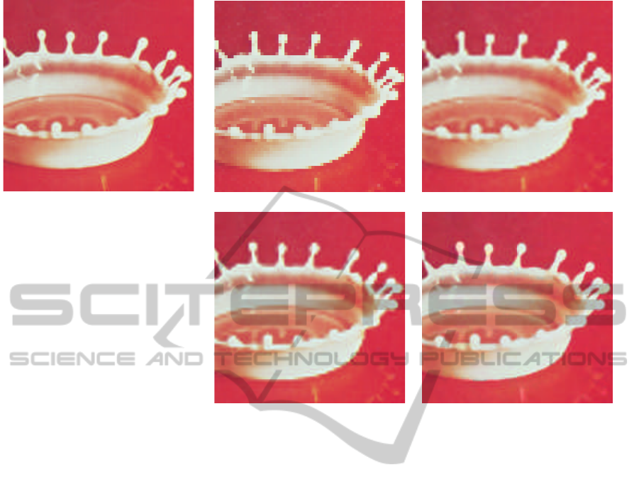
(a)
(b) (c)
(d) (e)
Figure 8: Results of image enlargement (factor = 4) : (a) OriginalC(b) NNIC(c) BCIC(d) NEC(e) Proposed.
method with the other image super resolution meth-
ods to improve image quality. After that, we imple-
ment it onto a field programmablegate array to realize
a real-time and high-quality video enlargement.
ACKNOWLEDGEMENTS
This work was supported by JSPS KAKENHI Grant
Number 24300092.
REFERENCES
Farsiu, S., Robinson, M., Elad, M., and Milanfar, P. (2004).
Fast and robust multiframe super resolution. In IEEE
Trans. Image Process., volume 13, pages 1327–1344.
Greenspan, H., Anderson, C. H., and Akber, S. (2000). Im-
age enhancement by nonlinear extrapolation in fre-
quency space. In IEEE Trans. Image Process., vol-
ume 9, pages 1035–1048.
Keys, R. G. (1981). Cubic convolution interpolation for dig-
ital image processing. In IEEE Trans. Acoust. Speech
Signal Process, volume 26, pages 1153–1160.
Lin, J. S. (1990). Two-dimensional signal processing and
image processing. Prentice-Hall, Inc., Upper Saddle
River, NJ, USA, 1st edition.
Siu, W. C. and Hung, K. W. (2012). Review of image inter-
polation and super-resolution. In Proc. of Asia-Pacific
Signal and Information Processing Association An-
nual Summit and Conference, pages 1–10.
Sugeno, M. (1985). Industrial applications of fuzzy control.
Elsevier Science Pub. Co.
Takagi, T. and Sugeno, M. (1985). Fuzzy identification of
systems and its applications to modeling and control.
In IEEE Trans. Systems, Man and Cybernetics, vol-
ume 15, pages 116–132.
Tamukoh, H., Kawano, H., Suetake, N., Sekine, M., Cha,
B., and Aso, T. (2013). A data embedded reduction
image generation method for high-quality image en-
largement. In Proc. of 7th Int. Conf. on Circuits, Sys-
tems, Signal and Telecommunications, pages 37–42.
Fuzzy-rule-embeddedReductionImageConstructionMethodforImageEnlargementwithHighMagnification
233
