
Study on Combining Model-driven Engineering and Scrum
to Produce Web Information Systems
F´abio P. Basso
1
, Raquel M. Pillat
1
, Fabricia Roos-Frantz
2
and Rafael Z. Frantz
2
1
Federal University of Rio de Janeiro, COPPE - PESC, Rio de Janeiro, Brazil
2
UNIJU
´
I University, Department of Exact Sciences and Engineering, Iju´ı, Brazil
Keywords:
Model-driven Engineering, Scrum, Mockup, Prototyping.
Abstract:
Model-driven engineering and agile methods are two important approaches to produce web information sys-
tems. However, whereas model-driven engineering is based on widely detailed models, agile methods such
as Scrum propose to not spend too much time in modelling. Model-driven engineering literature suggests
the use of pre-prototypes models that can be evaluated by clients before generating source code, and, agile
methods also propose to get client feedback soon after requirements are specified as user stories. Despite of
agile methods and pre-prototypes aim to quick validate requirements, their combined use must be carefully
studied. The quick design of pre-prototypes must be considered in order to achieve the benefits provided by
both approaches. In this paper we propose a new pre-prototype based methodology, which combines practices
to achieve quick feedback from clients from model-driven engineering and Scrum based agile methods. We
also report on a real-world case study concerning the development of a web information system.
1 INTRODUCTION
The approach of developing web information systems
from scratch is not trivial, since it is common to be-
gin software projects with vague ideas about what is
required by clients (Lami and Ferguson, 2007). Fur-
thermore, motivated by market trends for innovation
and time-to-market pressure, software requirements
usually change along the iterations in the software
development process (Landre et al., 2007). In or-
der to help Software Engineers in preliminary soft-
ware process phases, we present a new methodology
and tool support, combining Model-Driven Engineer-
ing (MDE) (B´ezivin, 2005) and some Agile Meth-
ods (Dyba and Dingsoyr, 2009).
MDE is a software development paradigm that
contributes to reduce time to deliver a working
application through a family of similar applica-
tions (Hutchinson et al., 2011). MDE allows the
specification of software requirements in a structured
manner (Petre, 2013), and generates testable proto-
types (Elkoutbi et al., 2006; Kavaldjian, 2007) trough
model transformations (OMG, 2013). Such proto-
types can be evaluated by clients in order to validate
software requirements (Souza et al., 2007).
Agile Methods such as Scrum are iterative and in-
cremental frameworks to manage software projects
focusing on continuous and quick delivery of work-
ing and tested pieces of software. They recommend
reducing the amount of generated documentation for
software requirements specifications (Shore and War-
den, 2008). By using short software process itera-
tions, Agile Methods allow for a quick validation of
software requirements soon after the analysis phase,
which returns a user story (a textual description about
the functionality being described).
Some studies suggest that MDE and Agile Meth-
ods can be used together (Rivero et al., 2012; Risti´c
et al., 2012). In this paper, we report on our ex-
perience applying our methodology to real-world
projects, conducted between 2010 and 2011, combin-
ing the use of MDE and Scrum in preliminary soft-
ware development phases. This piece of work indi-
cates that our methodology and tool are indeed ad-
herent with Agile Methods and that the mockup con-
struction, rapid prototyping, and frequent interaction
with clients to validate software requirements are the
keys in the development of web information systems.
We have also compared whether it was more produc-
tive to develop web information systems functionali-
ties not using MDE or with the assistance of our soft-
ware tool.
The rest of this paper is organised as follows: Sec-
tion 2 discusses the related work; Section 3, intro-
137
P. Basso F., M. Pillat R., Roos-Frantz F. and Z. Frantz R..
Study on Combining Model-driven Engineering and Scrum to Produce Web Information Systems.
DOI: 10.5220/0004859101370144
In Proceedings of the 16th International Conference on Enterprise Information Systems (ICEIS-2014), pages 137-144
ISBN: 978-989-758-028-4
Copyright
c
2014 SCITEPRESS (Science and Technology Publications, Lda.)

duces the main concepts used in our proposal; Sec-
tion 4 presents a case study; and, finally, Section 5
presents our conclusions.
2 RELATED WORK
We use mockups as input for model transformations
that allow us to generate multi-layered web informa-
tion systems. Similarly to our proposal, (Risti´c et al.,
2012) also generate mockups by means of templates.
(Rivero et al., 2012) generate MVC models in which
the View and the Controller layers are generated by
means of annotated mockups. Although both pro-
posals allow for designing pre-prototype models, they
are not aimed to be used in the whole software de-
velopment process. Unlike their proposal, we use
mockup models as input to generate not only the View
and Controller layers, but others, such as business
logic, data access object, entity/field validation, and
remote/web services.
Our methodology differs from traditional MDE-
based processes, such as those proposed by (Elk-
outbi et al., 2006; Stocq and Vanderdonckt, 2004;
Nunes and Schwabe, 2006), and (Souza et al., 2007),
since we start the process from mockups to generate
multi-layered models for web information systems.
Those authors propose the refinement of platform-
independent models (such as annotated class dia-
grams, use cases, collaboration diagrams, and activity
diagrams), to platform-specific models in a software
development process based on MDE. Those propos-
als apply a top-down approach to design web infor-
mation systems, in which input models, such as con-
ceptual models, are highly detailed before generating
a testable prototype. In our proposal, after specifying
user stories, Software Engineers design of a simple
domain class diagram without annotations, and then
uses templates to generate mockups, which are fur-
ther refined using more templates, making then do-
main models and mockups evolve together.
In addition, several MDE-based software tools
support the generation of GUI for web information
systems (Ceri et al., 2000; Kraus, 2007; Vanderdon-
ckt, 2005; Kavaldjian, 2007; Souza et al., 2007; We-
bRatio, 2013). However, those software tools require
a very detailed UML model as input to generate a
mockup. Examples of such inputs are use case dia-
grams, class diagrams, and activity diagrams, all of
them assigned with plain UML Profiles annotation.
Our proposal allows for the generation of the anno-
tations for the UML Profile using wizards, transfor-
mations, and manual configurations assisted by our
software tool.
3 METHODOLOGY OVERVIEW
An overview of our methodology is depicted in Fig-
ure 1. A complete description of the MDE tasks
and a comparison to our previous experiences is re-
ported in (Basso et al., 2014). It is important to notice
that the first MDE task is executed after specifying
user stories, when then start our contributions. These
MDE tasks are inspired on the OO-Method Presenta-
tion Model (PM) (Molina et al., 2002), a well adopted
methodology used to produce web information sys-
tems, such as Master-detail structures, Service layer
development, etc. Roughly speaking, after specifying
user stories, in this methodology, pre-prototypes are
designed and refined from step 1 to 3, as illustrated
for a single functionality in box (A). When the de-
sign of a pre-prototype is accepted by the client, then
the annotated UML model is generated as shown in
box (B) through steps 4 and 5. This model is used by
model-to-code transformations to then generate the
functional prototype in step 6 of box (C). Finally, a
working piece of software is delivered in step 7 as
a complete implemented functionality, and the client
can execute acceptance tests against it.
Similar to our related work, the model shown in
Figure 1, box (B), represents the last design stage of
a pre-prototype before it can be used to generate the
source code. Transforming a Platform-Independent
Model (PIM) to a Platform-Specific Model (PSM), as
illustrated in Figure 1, step 6, it is possible to gen-
erate a functional prototype for a web information
system. Different from related proposals that specify
the PIM manually, we generate it automatically based
on mockups constructed with the tasks shown in Fig-
ure 1, box (A). In this process a PIM 1 is transformed
into a PIM 2. Thus, a UML model (PIM 2) is gen-
erated by a model transformation using as input the
element named “Accepted Mockup Model” (PIM 1).
PIM 1 is a mockup in the final design stage be-
cause it owns GUI components strictly used in some
APIs and libraries. However, it is still a platform in-
terdependent model, since it is not yet mapped into a
specific platform as occurs in step 6. PIM 1 is also
generated by a transformation, using as input the pre-
prototype named “Preliminary Mockup Model”. This
is a Computational-Independent Model (CIM) which
represents a screen layout containing general purpose
GUI components. Finally, the “Preliminary Mockup
Model” is generated from transformation templates
taking as input a simple class diagram.
As depicted in Figure 1, box (A), steps 1 and 3,
the client interacts with the pre-prototypes in order to
find details that the functionality under specification
needs. Then, pre-prototypes are refined along steps
ICEIS2014-16thInternationalConferenceonEnterpriseInformationSystems
138
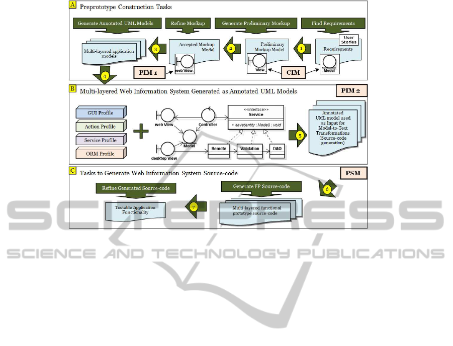
Figure 1: MDE Process used to generate an adapted MVC architecture for multi-layered applications.
1 to 5. Afterwards, the source code for a functional
prototype is generated in step 6 taking as input the
multi-layered model. Therefore, an important differ-
ence between UML based transformation approaches
and our proposal is that the former start from step 4
(by designing manually a model with multi-layered
details), whereas we start from step 1, by generating a
preliminary mockup model from transformation tem-
plates.
Box (B), in Figure 1, also exemplifies four UML
Profiles used by our approach to specify the details of
web information systems: the GUI Profile is used to
represent GUI components (view layer) since UML
has no diagram to draw GUIs; The Action Profile is
used to represent GUI component actions (controller
layer) as a UML activity diagram; The Service Pro-
file enables to define details about the business logic
layer for services that implement the classes (Remote,
Validation and DAO); and the ORM Profile is used to
apply object relational mappings on the model layer.
3.1 Combining MDE and Scrum
Scrum methods recommend to design important fea-
tures focusing on specific functionalities. To speed
up the design of these features, we recommend to
use transformation templates that are adequate to start
the design of a mockup considering some kinds of
functionalities for web information systems. Thus,
functionalities are characterised to particular kinds of
templates that can be used in sequence to design de-
tailed mockups as illustrated in Figure 2 by Sprint
Backlog documents. In this figure, these templates
are shown inside box (1) as different model trans-
formations to generate preliminary mockups (A) and
to refine mockups for more complex structures (B).
They require as input, classes of models associated
with functionalities (e.g., use cases and/or user sto-
ries) and allow the use of other types of transforma-
tions (from C to G) to detail a UML model with in-
formation of a single functionality. Thus, the activi-
ties a software engineer has to followwhen generating
mockups are: find domain classes that are related with
a single functionality, and, then, use these classes as
input for transformation templates.
Transformation templates are available in Mock-
upToME tool, meaning that Figure 2 (box 1) is com-
pletely assisted through model transformations. Thus,
a software engineer iteratively designs and validates
with clients the domain classes, actions (e.g., oper-
ations on persistency), mockups, and usability fea-
tures. These pre-prototypes are validated before start-
ing the development phase, reducing considerably the
rework in sprint cycles and also amongst the follow-
ing sprints, simplifying the transition from the re-
quirement analysis to the development phase.
Three kinds of transformations are executed to
perform the tasks illustrated in Figures 1 and 2: i)
Model-to-model transformations are applied to iden-
tify the requirements of a system, domain classes,
project classes, and user interactions with the system.
They are conducted in seven short tasks, shown inside
box (1) in Figure 2, which can be repeated inside the
same sprint with cycles. The pre-prototyping phase
illustrated in Figure 1 (A) is composed of guided,
automatic and manual transformations discussed fur-
StudyonCombiningModel-drivenEngineeringandScrumtoProduceWebInformationSystems
139
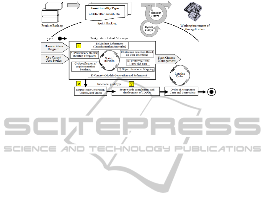
Figure 2: Scrum-based MDE Methodology supported by MockupToME tool.
ther; ii) Model-to-code transformations are used in
the phases represented in Figure 1 box (B) and (C)
after pre-prototypes are approved by clients. They are
responsible for generating the source code for the lay-
ers of the application and documentation, which will
be manually refined by the development team until
a fully functional prototype is reached. The source
code generation is a transformation guided by wiz-
ards; and, iii) Manual transformations are required to
complete fragments of source code that need to be
manually refined by software engineers.
3.2 Transformation Templates
A good command in domain-driven design (Evans,
2004) is required to operate MockupToME tool.
Thus, the domain classes must be classified as mas-
ter entities, which group other entities in support for
some functionality, or detail entities, which are sec-
ondary for a functionality and only complement it.
After identifying these entities, the next step is to
analyse the relationship amongst master and details
taking as base a mockup structure (screen layout) that
attempts to the functional requirement under develop-
ment. Such analysis allows to discover the fundamen-
tal characteristics of a target system, such as usability,
form validation rules, business rules, as well as, other
relationships amongst the entities master and details
that have not been identified previously in the require-
ment analysis phase.
MockupToME tool is used to specify mockups
through model transformations named Startup Tem-
plates We found that in the context of web information
systems, some functionality can be classified as part
of a same structural pattern (template) such as some
kinds of GUI forms, GUI filters, and reports. There-
fore, startup templates are model transformers that al-
low generating preliminary GUI forms based on the
visual presentation structure of a template (Han and
Liu, 2010; Aquino et al., 2010).
The options for startup templates supported by
MockupToME tool are: i) Persistency structures
named CRUD. Many variations for this kind of GUI
form are available; ii) Filtering structures to support
data retrieve from databases; iii) Structures to data
presentation such as reports, tables, and so on; and, iv)
Merges between different GUI structures: such as re-
ports that also contain editable fields (merge between
CRUD and reports).
In order to allow the representation of details con-
cerning actions performed by the client on mockup
elements, known in the literature as Action Seman-
tics (OMG, 2013), each GUI component can receive
annotations that differentiate it from a common com-
ponent, such as exemplified with stereotypes and tags
in Figure 3 (B). Besides, it provides information to
generate MVC layers through model-to-model trans-
formations. Annotations can be used to enrich a
preliminary mockup based on facilities available in
MockupToME tool. Such facilities are model trans-
formations that allow the use of different refinement
strategies to generate variants of CRUD forms, data
reports, and so on.
Mockup refinement occurs with support of guided
strategies, exemplified as follows: let us assume
the one-to-many relationship between classes Client,
Category, and CreditCard. When refining the GUI
form for functionality “register a client”, each asso-
ciation can be handled in many ways, using strate-
gies to support a particular user interaction. In or-
der to add some items of the Category entity inside
the Client entity, a software engineer may prefer to
use the strategy one-to-many called “Source-Target
master-detail”, as shown in Figure 3 (A) and labeled
“Category Preferences (0..* Detail)”. For CreditCard
entity, a software engineer can choose the default
ICEIS2014-16thInternationalConferenceonEnterpriseInformationSystems
140

“Table master-detail” strategy labelled “Credit Cards
(0..* Detail)”.
Similarly to startup templates, guided strategies
are available as model transformations in Mockup-
ToME tool. Transformations can be executed in-
side mockup drawings, changing the model (mockups
and UML elements) during the design phase, through
popup-menus. Software engineers can undo transfor-
mations while deciding which strategy best fits to ex-
press a specific part of the required functionality. In
other words, they can alternate between strategies for
each association of Client class facing a requirement
analysis. Besides, each GUI component shown with
an icon of alert, see the Save and Remove buttons
shown in Figure 3 (A), indicates that such compo-
nent can be refined with other transformations, also
available as dynamic popups for each GUI compo-
nent. Therefore, the tool allows specifying many lev-
els of master-detail structures, such as recommended
by the domain-driven design approach.
Finally, when pre-prototypes are approved, the re-
fined mockup is transformed into other application
layers, shown in Figure 1 box (B). These are actually
other levels of models, such as concrete GUI models
(web or mobile), persistency layer, actions, and flow
layers. These models can also be refined and further
be used to generate source code.
4 CASE STUDY
The case study was conducted between 2010 and
2011, and the software under analysis was developed
by two Brazilian software companies, in this paper
denominated Company A and Company B. Company
A used our methodology and MockupToME to de-
velop a web information system, and Company B was
responsible for the analysis phase. The goal was to
compare the team productivityand identify the perfor-
mance of our proposal when using it combined with
Scrum. The object of this case study is a web informa-
tion system to maintain financial projects. It is a sys-
tem made up of Create-Read-Update-Delete (CRUD)
functionalities, and its purpose is to evaluate our pro-
posal in regard to the development of some function-
alities with and without the support of MockupToME
tool.
4.1 Context Selection
The development team managed by Company A
(Team 1) used the MockupToME tool, whereas the
team of Company B (Team 2) did not use it, while
both companies do/use Scrum. Both teams developed
similar functionalities as subsystems of the same soft-
ware, using different technologies. Teams are com-
posed of: a Scrum Master; a Java developer, who
has been trained for a month; a Tester, and an An-
alyst who wrote user stories. Additionally to Team
1, the Analyst and the Developer also designed GUIs
and UML models containing only a clean conceptual
model (e.g., class diagram without stereotypes and
tags). Team 2 used Java Server Faces (JSF) technol-
ogy to develop the View layer, whereas Team 1 used
Java Server Pages (JSP) and Spring Framework con-
trollers to code the View and Controller layer. This is
a confounding factor in this study, since JSF reduces
the amount of the code necessary for these layers and
simplify the maintenance (Mann, 2005).
4.2 Attributes and Measures
Our goal was to observe how our methodology con-
tributes in the development of a single system that
is developed from scratch considering a Scrum-based
methodology. With this in mind, since Scrum recom-
mends sprints with short duration, it is important to
compare the number of days required by each team to
execute each sprint. In this sense, we planned short
duration sprints composed of five days of work, eight
hours a day. Then we compared the number of days
used by Team 1 to deliver a working piece of soft-
ware, with Team 2, which developed manually the
source-code. This is a quantitative measure that al-
lows us to observe the required time to design the
pre-prototypes (our MDE-based approach) and its im-
pact on the duration of a sprint in comparison to a non
MDE-based approach.
In this case study, we did not collect other quan-
titative measures, except for the size of the produced
software. We collected qualitative attributes used in-
ternally by Company A, such as the usability of the
MockupToME tool, the required improvements, and
the number of bugs. Some of the qualitative attributes
collected from the project leaders along and at the fi-
nal of the project were used to answer the following
two research questions:
RQ1. Once that some practitioners consider there
can be some incompatibility between MDE and
Scrum, is it possible to use MockupToME tool
and the proposed methodology with Scrum in a
real-world project?
StudyonCombiningModel-drivenEngineeringandScrumtoProduceWebInformationSystems
141
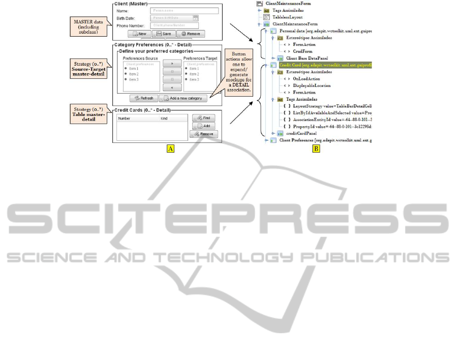
Figure 3: (A) Two guided strategies for one-to-many master-detail (B) annotated mockup model elements.
RQ2. Does the use of the MockupToME tool allows
to build working web information system, on the
first version (started from scratch), faster than a
version produced by a team that does not use our
tool and methodology?
4.3 Executing the Study
Initially, we provided a Java web framework that had
18 basic entity classes to support access control, cus-
tomisable CRUDs and filters, functionalities to handle
files, and images that are common features in many
web information systems. A tutorial on WCTSam-
ple containing about 150 pages with guidelines and
examples was provided to Team 1. We also trained
Team 1 on MockupToME tool, UML, and on WCT-
Sample Java Architecture. Moreover, because Team
1 was more familiar with a technology to program
rich web GUI, we also adapted some model trans-
formations of type model-to-code from the original
mapped technology named Dojotoolkit to the new tar-
get named JQuery. Finally, we provided a tutorial
and daily meetings, with mentoring for two weeks of
pair programming, towards the development of spe-
cific functionalities for a period of one month, before
the developer of Company A started to write the ac-
tual source-code. Thus, due to the required training
to understand and apply our proposal, Team 1 started
producing latter than Team 2.
Checkpoint 1. After two months of work with our
methodology and using our tool, a checkpoint was
carried out by the companies involved in the project
to evaluate the productivity of both teams, measured
by the speed to deliver a working piece of the appli-
cation. Team 1 was producing slower than Team 2,
that surprised us with their advances in development.
Team 1 used Sprints with eight days whereas Team 2
used Sprints with five days to develop similar func-
tionalities.
Checkpoint 2. Four months after the start of the
project, another checkpoint was carried out. Along
the project, Team 1 increased the speed in deliver-
ing working functionalities in each sprint. Thus, the
deliveries were slightly different between the teams,
suggesting that the MockupToME tool could save
time for Team 1, using Sprints with four days of
work).
Along this period, the Team 1 identified failures
in transformations. Such problem had an impact on
the productivity, but did not stop the development of
functionalities. Finally, at the fifth month all the func-
tionalities addressed by our proposal were finished,
then more complex functionalities were developed
not using MDE. The overall project ended in 2011,
whose Team 1 was allocated along five months.
4.4 Analysis and Interpretation of
Quantitative Data
Regarding Checkpoint 1, we identified that the learn-
ing curve for Team 1 was steeper than for the other
team, which had to learn only about the Java architec-
ture. Initial Sprints requires more days in first weeks,
because the team is still unfamiliar with the problem
domain and also with the development tools (Shore
and Warden, 2008). In this sense, the techniques
and tools introduced by our methodology increased
the time necessary by Team 1 to surpass the learn-
ing curve period. Moreover, MockupToME presented
some bugs related to pre-prototype modelling and
also to source code generation. These bugs were fixed
while sprints were executed, which required longer
sprints of Team 1.
Regarding Checkpoint 2, although the number
of days to complete a sprint decreased considerably
compared with the first checkpoint, the generated
code still required modifications by Team 1 until a
full source code was generated in last three Sprints,
ICEIS2014-16thInternationalConferenceonEnterpriseInformationSystems
142

not requiring adjustments anymore.
4.5 Qualitative Analysis About the
Research Questions
At the end of the project, we queried the team leaders
about the two research questions. For the first ques-
tion, they reported that our methodology and Mock-
upToME tool can be used with Scrum, given that
companies have been designing mockups.
For the second research question, team leaders
stated they cannot assert that our methodology im-
proves productivity compared with Team 2, which
did not use the MockupToME tool. As the designed
model was used in a single application, they did not
noticed any benefit promoted by MDE in regard to
speed up their production. However, they reported
no changes motivated by missing or misunderstood
requirements between sprint cycles (a positive feed-
back). We have considered this a benefit that our
methodology and tool promoted in preliminary soft-
ware phases.
Team leaders also reported the following benefits:
i) better source code organisation and modularisation
compared with their previous practices; ii) facilities
to change the generated source code; iii) facilities to
design mockup models; iv) they also stated an expec-
tation regarding benefits that could be promoted by
further reuse of the designed model.
Finally, team leaders reported that would be bene-
fit if model transformations tasks could be used inside
Eclipse workspace instead of in processes started with
menus in MockupToME. Recently, they requested an
integration with the Mylyn plugin to manage MDE
tasks and developmenttasks in the same environment.
We believe that this is interesting to allow us reducing
the learning curve for developers.
5 CONCLUSIONS
This paper has presented a methodology and tool sup-
port to develop web information systems, which com-
bine the use of Model-DrivenEngineering (MDE) and
Scrum approaches. Such methodology and tool al-
low performing quick design and validation of pre-
prototype models. We presented a case study con-
ducted in industry, evaluating the time spent by two
teams to conclude sprints with similar functionalities
along five moths. In this context, Team 1 produced
a subsystem using our methodology and tool sup-
port whereas Team 2 used regular development tools
with a Scrum-based framework. This experience al-
lowed us find out some benefits and drawbacks of our
methodology.
The industrial case study allowed to evaluate two
questions: 1) Once that some practitioners consider
there can be some incompatibility between MDE and
Scrum, is it possible to use MockupToME tool and
the proposed methodologywith Scrum in a real-world
project? 2) Does the use of the MockupToME tool al-
lows to build working web information system, on the
first version (started from scratch), faster than a ver-
sion produced by a team that does not use our tool and
methodology?
The reported case study enabled us to answer the
questions above: 1) Since Scrum is agnostic to the use
of technologies, the proposed MDE methodology and
the MockupToME tool can be used with Scrum; 2)
Although the MockupToME tool enables to quickly
produce functional prototypes, it is not possible to as-
sert that by using the tool a team is more productive
than without using it, taking into account a project
started from scratch which does not use a model de-
signed previously (i.e. the model still does not ex-
ist). Therefore, we found in practice that quick pro-
totyping help to speed-up the design of models (an-
notated mockups), allowing a quick feedback from
clients; however, compared to a team that do not use
MDE, our methodology did not increased the soft-
ware productivity for started from scratch web infor-
mation systems as we are expecting.
A software process that uses MDE demands from
the designers more time to specify GUI models
(mockups) annotated with tags and stereotypes. In or-
der to quickly design these models, we automatically
annotate pre-prototypes (i.e. adding action semantics)
with the help of MockupToME tool. Therefore, we
found that even generating such annotations on GUI
models it was not possible to guarantee a reduction
in time in comparison with functionalities produced
without using MDE. However, we observed benefits
in comparison with our previous practices on MDE,
which manually annotate pre-prototypes.
It is known that a MDE promise is to increase
the productivity in future reuse of the designed mod-
els. This study was limited to evaluate the proposed
methodology and does not attempt to confirm or deny
this promise. Having it in mind, this should be ex-
plored in order to better comprehend benefits and
drawbacks in a combined use of MDE and Scrum.
ACKNOWLEDGEMENT
The research work on which we report in this paper is
supported by FINEP, CNPq, CAPES, FAPERGS, and
the internal Research Programme at UNIJUI Univer-
StudyonCombiningModel-drivenEngineeringandScrumtoProduceWebInformationSystems
143

sity.
REFERENCES
Aquino, N., Vanderdonckt, J., and Pastor, O. (2010). Trans-
formation templates: adding flexibility to model-
driven engineering of user interfaces. In Proceedings
of ACM Symposium on Applied Computing, pages
1195–1202.
Basso, F. P., Pillat, R. M., Rooz-Frantz, F., and Frantz, R. Z.
(2014). Assisted tasks to generate pre-prototypes for
web information systems. In 16th International Con-
ference on Enterprise Information Systems (ICEIS).
Lisbon, Portugal, April 27-30 2014. (To appear),
ICEIS’14.
B´ezivin, J. (2005). On the unification power of models.
Software and System Modeling, 4(2):171–188.
Ceri, S., Fraternali, P., and Bongio, A. (2000). Web model-
ing language (WebML): a modeling language for de-
signing web sites. Computer Networks, 33(1-6):137–
157.
Dyba, T. and Dingsoyr, T. (2009). What do we know
about agile software development? Software, IEEE,
26(5):6–9.
Elkoutbi, M., Khriss, I., and Keller, R. K. (2006). Auto-
mated prototyping of user interfaces based on UML
scenarios. Automated Software Engineering, 13(1):5–
40.
Evans, E. (2004). Domain-driven design: tackling complex-
ity in the heart of software. Addison Wesley.
Han, H. and Liu, B. (2010). Problems, solutions and new
opportunities: using pagelet-based templates in devel-
opment of flexible and extensible web applications. In
Proceedings of the 12th International Conference on
Information Integration and Web-based Applications
& Services, iiWAS’10, pages 679–682.
Hutchinson, J., Whittle, J., Rouncefield, M., and Kristof-
fersen, S. (2011). Empirical assessment of MDE in in-
dustry. In Proceedings of the 33rd International Con-
ference on Software Engineering, pages 471–480.
Kavaldjian, S. (2007). A model-driven approach to gener-
ating user interfaces. In The 6th Joint Meeting on Eu-
ropean software engineering conference and the ACM
SIGSOFT symposium on the foundations of software
engineering: companion papers, pages 603–606.
Kraus, A. (2007). Model Driven Software Engineering for
Web Applications. PhD thesis.
Lami, G. and Ferguson, R. W. (2007). An empirical study
on the impact of automation on the requirements anal-
ysis process. J. Comput. Sci. Technol., 22(3):338–347.
Landre, E., Wesenberg, H., and Olmheim, J. (2007). Ag-
ile enterprise software development using domain-
driven design and test first. In Companion to the
22nd ACM SIGPLAN conference on Object-oriented
programming systems and applications companion,
pages 983–993.
Mann, K. (2005). Java Server Faces in Action. Manning
Publications.
Molina, P. J., Meli´a, S., and Pastor, O. (2002). Just-ui: A
user interface specification model. In Computer-Aided
Design of User Interfaces III, pages 63–74.
Nunes, D. A. and Schwabe, D. (2006). Rapid prototyping
of web applications combining domain specific lan-
guages and model driven design. In Proceedings of
the 6th international conference on Web engineering,
pages 153–160.
OMG (2013). MDA object management group MDA spec-
ifications.
Petre, M. (2013). UML in practice. In Proceedings of the
2013 International Conference on Software Engineer-
ing, ICSE ’13, pages 722–731.
Risti´c, S., Lukovi´c, I., Aleksi´c, S., Banovi´c, J., and Al-
Dahoud, A. (2012). An approach to the specification
of user interface templates for business applications.
In Proceedings of the Fifth Balkan Conference in In-
formatics, pages 124–129.
Rivero, J. M., Grigera, J., Rossi, G., Luna, E. R., and Koch,
N. (2012). Towards agile model-driven web engineer-
ing. In IS Olympics: Information Systems in a Diverse
World, volume 107, pages 142–155.
Shore, J. and Warden, S. (2008). The Art of Agile Develop-
ment. O’Reilly.
Souza, V. E. S., Falbo, R. D. A., and Guizzardi, G. (2007).
A UML profile for modeling framework-based web
information systems. In 12th International Workshop
on Exploring Modelling Methods in Systems Analysis
and Design EMMSAD ’2007, pages 153–162.
Stocq, J. and Vanderdonckt, J. (2004). A domain model-
driven approach for producing user interfaces to
multi-platform information systems. In Proceedings
of the working conference on Advanced visual inter-
faces, pages 395–398.
Vanderdonckt, J. (2005). A MDA-compliant environment
for developing user interfaces of information systems.
In Proceedings of the 17th international conference
on Advanced Information Systems Engineering, pages
16–31.
WebRatio (2013). Web ratio web page.
ICEIS2014-16thInternationalConferenceonEnterpriseInformationSystems
144
