
Model-driven Structural Design of Software-intensive Systems Using
SysML Blocks and UML Classes
Marcel da Silva Melo
1
and Michel S. Soares
2
1
Faculty of Computing, Federal University of Uberlˆandia, Uberlˆandia, Brazil
2
Computing Department, Federal University of Sergipe, S˜ao Crist´ov˜ao, Sergipe, Brazil
Keywords:
SysML Block diagram, UML Class diagram, Software Design, Model-Driven Software Engineering, ATL
Transformation Language.
Abstract:
One particular characteristic of software-intensive systems is that software is a fundamental component to-
gether with other components. For the software design counterpart, both for structural and dynamic views,
UML is one of the most used modeling language. However, UML is weak in modeling elements of a software-
intensive system that are not software. This is the main reason why the Systems Modeling Language (SysML),
a UML profile, was introduced by OMG. One objective of this article is to combine the SysML Block diagram
and the UML Class diagram to design the structural view of a software-intensive system architecture. A meta-
model describing the relationship between the two diagrams and an automatic model-driven transformation
using the ATL language are proposed. The evaluation was performed by applying the meta-model in practice
to develop software-intensive systems in the field of road traffic management, as shown in the case study.
1 INTRODUCTION
Software-intensive systems (Tiako, 2008) (Hinchey
et al., 2008) are large, complex systems in which
software is an essential component, interacting with
other elements such as other software, systems, de-
vices, actuators, sensors and with people. As soft-
ware is an essential part of these systems, it influences
the design, deployment, and evolution of the system
as a whole (ISO-IEC, 2007). Examples of software-
intensive systems can be found in many sectors, such
as manufacturing plants, transportation, telecommu-
nication and health care.
Designing software-intensive systems is a chal-
lenging activity for many reasons. The proper en-
vironment in which software-intensive systems act
poses great challenges. Software-intensive systems
are frequently used to control critical infrastructures
in which any error, non-conformance or even re-
sponse delays may cause enormous financial damage
or even jeopardize human life. Designing and creat-
ing models are important activities to improve com-
munication between teams and to significantly dimin-
ishing natural language ambiguities (Ludewig, 2003).
Typically, in Systems and Software Engineering, an
artifact is considered to be a model if it has a graph-
ical, formal or mathematical representation (B´ezivin,
2006).
Currently, there are a variety of modeling lan-
guages, methods, and techniques applied to all phases
of software systems development. An extensive list of
techniques for software design activities is presented
in (Jiang et al., 2008). For instance, the structural el-
ements of software have long been modeled using the
Entity-Relationship model or simple block diagrams
with unclear semantics (Edwards and Lee, 2003).
There is no doubt that UML (OMG-UML, 2010) has
been widely applied to the development of software
in industry. Despite its relative success, the language
has been heavily criticized (Bell, 2004) (France et al.,
2006) (Andr´e et al., 2007) (Soares and Vrancken,
2009). The most relevant criticism of UML regarding
this article is that UML is weak in modeling elements
of a software-intensive system that are not software.
This is the main reason why SysML (OMG-SysML,
2010) was proposed. SysML is a systems model-
ing language that supports the specification, analysis,
design, verification and validation of a broad range
of complex systems. The language is derived from
UML, taking into account systems aspects such as
hardware, information, processes and personnel.
The focus of this article is on the design phase
of software-intensive systems, more specifically the
design of the structural view of a software-intensive
193
da Silva Melo M. and S. Soares M..
Model-driven Structural Design of Software-intensive Systems Using SysML Blocks and UML Classes.
DOI: 10.5220/0004871301930200
In Proceedings of the 16th International Conference on Enterprise Information Systems (ICEIS-2014), pages 193-200
ISBN: 978-989-758-028-4
Copyright
c
2014 SCITEPRESS (Science and Technology Publications, Lda.)
system architecture. Therefore, it is of utmost im-
portance that not only the software part of these sys-
tems are modeled, but also the system elements are
modeled. This article has two main objectives. The
first one is to describe the introduction of SysML as a
modeling language in the development process of dis-
tributed real-time software-intensive systems. More
specifically, the SysML Block diagram is applied in
practice to describe the structural architecture in the
field of road-traffic management. SysML has been
applied to a number of projects (Viehl et al., 2006)
(Laleau et al., 2010) in various fields, such as large
telescopes (Karban et al., 2008), car manufacturing
(Balmelli et al., 2006), industrial process control ap-
plications (Hastbacka et al., 2011), and road traffic
management systems (Soares et al., 2011).
The second objectiveis to propose a metamodel to
describe the relationship between the SysML Block
and the UML Class diagrams, which was not well-
described in the SysML specification (OMG-SysML,
2010). This relationship is then implemented using a
model-driven approach. An automatic transformation
using the ATL language (Jouault and Kurtev, 2005) is
performed based on the described metamodel.
Other model-driven approaches combining
SysML and ATL are not frequent in the literature,
because of the novelty of these languages. One
example can be found in (Colombo et al., 2012), in
which the transformation based on ATL is performed
considering only the SysML metamodel, i.e., the
authors proposed a transformation from analysis
models to design models by refining the SysML
diagrams. ATL was chosen in this research because it
has been successfully applied for transformations in
real applications as described in the literature (Jouault
et al., 2008) (Kim et al., 2012) (Goknil et al., 2014).
In addition, ATL provides an adequate tool support,
as the language is part of the Eclipse project. The
approach is applied to a practical application in the
field of road-traffic management, in which important
software-intensive systems are implemented in order
to support modern life.
2 BASICS ON SysML BLOCK
DIAGRAMS
SysML is considered both a subset and an extension
of UML. As a subset, UML diagrams considered too
specific for software (Objects and Deployment dia-
grams) or redundant with other diagrams (Commu-
nication and Time Diagrams) were not included in
SysML. Some diagrams are derived from UML with-
out significant changes (State-Machine, Use Case, Se-
quence, and Package Diagrams), other diagrams are
derived with changes (Block, Activity, Internal Block
Diagrams) and there are two new diagrams (Require-
ments and Parametric Diagrams). As a matter of fact,
SysML is compatible with UML, which can facilitate
the integration of the disciplines of Software and Sys-
tem Engineering. Nevertheless, there is still lack of
research on using both languages together, and the
boundaries and relationships are not yet clear.
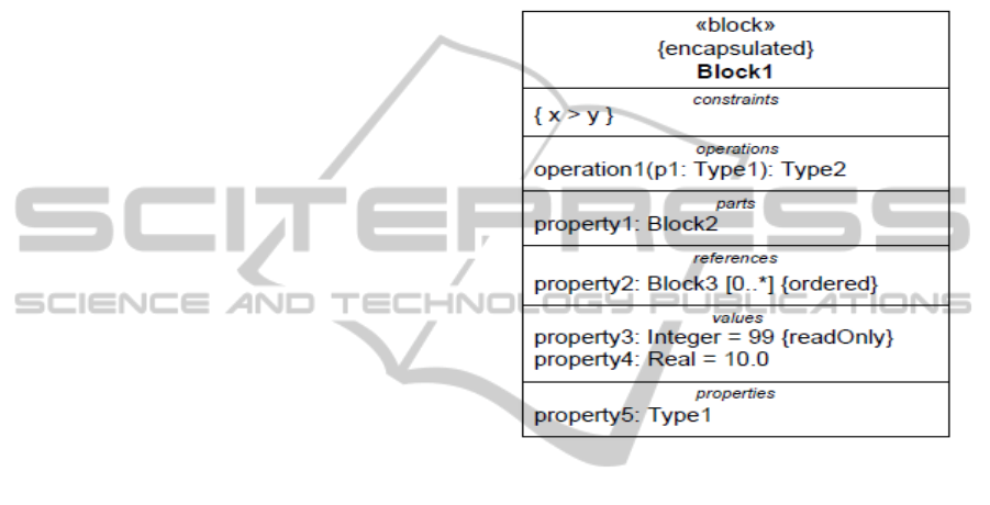
Figure 1: A SysML Block.
The SysML Block (Figure 1) extends the UML
Class by including additional elements and con-
straints. A SysML Block can be divided into named
compartments, which can be defined specifically for
each type of system. For instance, a compartment
can represent properties, operations, or parts. A prop-
erty can represent a role in the context of its enclosing
block. A part belonging to a block defines a local us-
age of its defining block within the specific context to
which the part belongs. Operations describe the be-
havior of a system.
SysML Blocks provide a general-purposecapabil-
ity to describe the architecture of a system (OMG-
SysML, 2010). The SysML Block diagram provides
the ability to represent a system hierarchy. It can also
represent parts of software-intensive systems at many
levels of abstraction. Elements of a software-intensive
system such as hardware, procedures, data, and per-
sons are modeled with the SysML Block diagram.
The design of the system architecture is described
by means of blocks, with focus not only on the soft-
ware structure of each system element, but also on the
general structure, including parts of each block, con-
straints and properties not necessarily related to soft-
ware. With the SysML Block diagram, system’s ele-
ICEIS2014-16thInternationalConferenceonEnterpriseInformationSystems
194
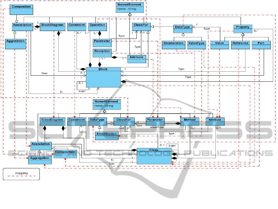
Figure 2: Metamodel to map SysML Blocks to UML Classes.
ments are identified, together with their relationships,
properties, and operations.
3 RELATING SysML BLOCKS
WITH UML CLASS DIAGRAM
Once the structural view of the system has been de-
fined from the systems engineering point of view, then
software engineers have to map the system elements
modeled as SysML Blocks to software classes and
objects. The choice here is to use the UML Class
diagram to represent the model of software classes.
This choice is natural given that SysML and UML
are modeling languages with roots on the same meta-
metamodel, the MOF (OMG, 2006). Therefore, phys-
ical elements of a system, modeled as SysML Blocks,
are later implemented in a software system as a corre-
sponding software object, once the physical element
is included into the software architecture.
SysML Blocks are candidates to be refined into
one or more UML Classes during the software design
and implementation phases. However, the refinement
is not automatic. This is a modeling activity that, by
its own nature, has no strict rules. Some useful guide-
lines and a metamodel (Fig. 2) for the relationship are
proposed in this section.
Properties, operations and constraints are com-
partments proposed in the SysML specification. Prop-
erties are mapped as attributes of a class, if they are
related to states, or to methods, if they are related to
operations. Within SysML, all properties are public.
For the mapping, good design practices of the object-
oriented paradigm shall be applied (e.g., information
hiding). Therefore, properties are most often mapped
as private or protected attributes of a class.
Operations are mapped into at least one software
method, normally as a public element of the class in-
terface. The reason is that the system operation can
actually be implemented using a group of software
methods instead of only one. Systems and software
engineers have to work together in order to decide the
best solution for this mapping.
SysML Blocks are related to each other through
associations. These can be normal associations,
meaning that there is a relationship between the as-
sociated blocks, or stronger relationships, in this case
composition or aggregation. The semantic choice of
the former two types of association depends on strong
ownership and coincident lifetime of the part and the
whole.
Model-drivenStructuralDesignofSoftware-intensiveSystemsUsingSysMLBlocksandUMLClasses
195
Within the SysML Block diagram, properties, op-
erations, receptions, parts, references and values are
compartments of a block. In the proposed transforma-
tion, properties and values are mapped as attributes of
a UML class. Operations and receptions are mapped
as at least one method of a class, almost always as
a public member, but may be mapped as a group of
methods. Systems engineers and software engineers
must work together with the purpose of deciding the
solution to this mapping.
Parts and references are represented in the model
as associations between blocks. In the SysML Block
diagram, parts represent that the block to be imple-
mented is composed of other blocks. This character-
istic is represented in the UML Class diagram using
the composition kind of association. References indi-
cate that the block to be mapped uses other blocks, but
is not composed of other blocks. This characteristic is
mapped in the UML Class diagram using the aggre-
gation kind of association. For all mapping, the asso-
ciations and their cardinalities are kept unchanged.
All properties are public in SysML, but this is not
wise in UML. According to the concept of informa-
tion hiding of the object-oriented paradigm, a differ-
entiation between private and public elements is es-
sential.
4 RULES SPECIFIED WITH ATL
ATL (Atlas Transformation Language) (Jouault and
Kurtev, 2005) was chosen as the language for imple-
menting the transformation from SysML Block di-
agrams to UML Class diagrams. ATL is a model-
to-model transformation language. The choice was
taken considering many aspects. ATL is part of the
M2M Eclipse project with an active discussion group
and many examples and case studies applied even in
industry (Selim et al., 2012). As an Eclipse project,
ATL proposes to the community a complete Eclipse
IDE (Integrated Development Environment) coming
along with the ATL language and core components.
The language is one of the most mature technologies
in the model-drivenfieldof research (Bruneli`ere et al.,
2010). The Eclipse editor provides standard resources
for the implementation, including syntax highlighting
and debugger.
In order to create and execute the ATL trans-
formation, two metamodels were used: the SysML
Block diagram and the UML Class diagram meta-
models. These metamodels are exactly the same as
proposed in OMG specifications. Using these meta-
models, ATL rules were defined with the purpose of
transforming blocks into classes. Overall, ten ATL
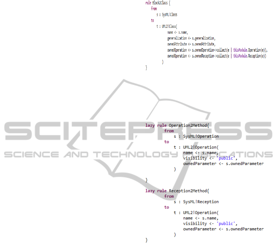
Figure 3: ATL Rule’ Block2Class.
rules were implemented to create the transformation
(see Table 1). Due to lack of space in this article, only
four of these rules implemented in ATL are presented
in the article as follows.
Figure 4: ATL Rules’ operation2operation and recep-
tion2operation.
The purpose of the Block2Class rule (Fig. 3) is
to transform each SysML Block into a correspond-
ing UML Class. The elements of a Block are trans-
formed as well. Properties and values in a Block are
transformed into class attributes, and operations and
receptions are transformed into class methods. Spe-
cific rules for transforming operations and receptions
are presented in Fig. 4.
Rules Operation2Method and Reception2Method
(Fig. 4) have the objective of transforming operations
and receptions into class methods. Operations and
receptions are simple elements of a SysML Block,
containing for their specifications only name, visibil-
ity, and parameters. Therefore, the transformations
were quite simple, with only an additional transfor-
mation named ParameterAttribute2Parameter in or-
der to transform parameters of operations into param-
ICEIS2014-16thInternationalConferenceonEnterpriseInformationSystems
196
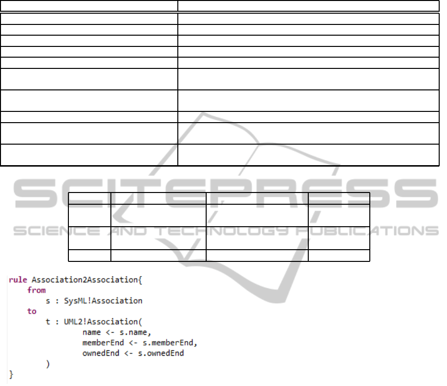
Table 1: Rules in ATL.
Rules Description
Model2Model Transforms a SysML Block diagram into a UML Class diagram
Block2Class Transforms each SysML Block into a UML Class
Property2Attribute Transforms Block properties into Class attributes
Operation2Method Transforms Block operations into Class methods
Reception2Method Transforms Block receptions into Class methods
ParameterAttribute2Parameter Transforms parameters of operations and attributes of receptions
into parameters of methods of a Class
AssociationPartReference2Association Transforms parts, references and associations into Class associa-
tions
DataType2DataType Transforms a DataType of a Block into a DataType of a Class
Enumeration2Enumeration Transforms an Enumeration of a Block into an Enumeration of a
Class
EnumerationLiteral2EnumerationLiteral Transforms an EnumerationLiteral of a Block into an Enumera-
tionLiteral of a Class
Table 2: Elements of the Software Architecture.
Layer Geographic element Monitoring Control
Network Network OD-matrix ODMGR.
Route Route travel time Route Mgr.
Link Link Capacity Link Mgr.
merge/choice point Avg. speed, turn fractions Junction Mgr.
Point sensor/actuator position Speed, flow, occupancy Actuator Mgr.
Figure 5: ATL Rule Association2Association.
eters of methods.
Parts and references of a SysML Block are repre-
sented in the model as associations of type, respec-
tively, composition and aggregation. Thus, the rule
applied to transform associations between blocks into
associations between classes will also be applied to
transform parts and references.
5 STRUTURAL ARCHITECTURE
OF THE CASE STUDY
The SysML Block diagram is applied in this article to
represent the structural view architecture of systems.
The case study shown in this section is of an archi-
tecture for a road traffic management system (RTMS)
(Almejalli et al., 2008) (Almejalli et al., 2009), which
are software-intensive systems used in activities such
as controlling, predicting, visualizing, and monitor-
ing road traffic. The structural view architecture de-
scribes which elements (see Table 2) cooperate with
each other in a high level manner, without concerns
about how this interaction is done. These network el-
ements are:
• Origin-destination Managers. (ODMGR) rep-
resent the relation between an origin and a desti-
nation and comprise one or more routes.
• Route Managers. control the set of routes from
one origin to one destination.
• Links. come in two types, Main links and Acces-
sor links. The Main link is the link from the merge
point to the choice point and the Accessor link is
the link from the choice point to the merge point.
• Junctions. comprise the outgoing Main link and
the incoming Accessor links of a crossing or mo-
torway junction. A junction is a location where
traffic can change its routes, directions and some-
times even the mode of travel.
• Control Schemes. are coherent set of measures
triggered by recurring patterns in the traffic state,
such as the morning rush hours or the weekend
exodus.
Model-drivenStructuralDesignofSoftware-intensiveSystemsUsingSysMLBlocksandUMLClasses
197
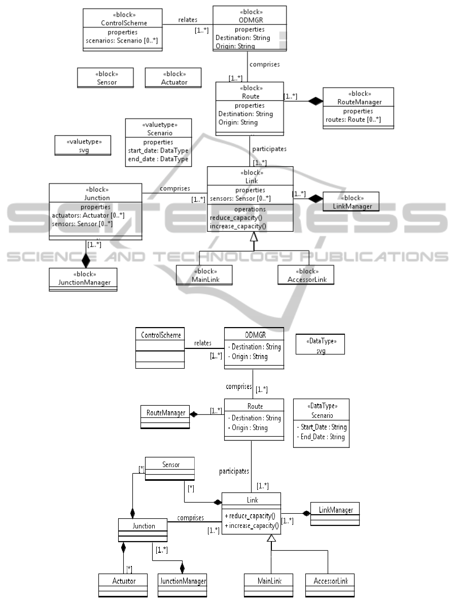
Figure 6: Logical view using SysML Block diagram.
Figure 7: Logical view using UML Class diagram.
ICEIS2014-16thInternationalConferenceonEnterpriseInformationSystems
198

The representation of the structural architecture
view is shown in Fig. 6 using a SysML Block dia-
gram. The distributed components have to commu-
nicate with each other, as they work in cooperation.
They continuously measure the traffic state and com-
municate about it to other links in real-time. For in-
stance, links have to communicate with other links in
order to achieve a traffic state. Routes participate in at
least one link, but they can participate in more links.
The initial SysML Block model was designed us-
ing the Papyrus tool, which is integrated into the
TopCased tool. Papyrus offers all support to create
SysML models, including the automatic generation
of a xmi file, which is the entry model to create ATL
transformations. After execution of the transforma-
tion, a xmi file is generated with the UML Class. This
file is then read to be presented in a graphical manner.
The final result is presented in Fig. 7. With this UML
Class diagram, a Model-to-Code transformation can
be performed. In this research, the TopCased tool al-
lowed the generation of Java source code automati-
cally.
In terms of the system example presented in this
section, sensors and actuators objects only exist be-
cause they belong to a junction object. The same
holds to sensor objects related to link objects. As a
result, they are all represented with the composition
relationship. Other compartments of a SysML Block
do not have a straightforward mapping, in particular
the ones specific to the domain. Thus, each case is
taken into account carefully. For instance, the Con-
trol Scheme is actually refined to a control class, re-
sponsible to implement the proposed scenarios. Each
scenario presented in the “scenario compartment” is
designed as a Use Case, and implemented in software
through the UML Classes.
The proposed meta-model which is the basis for
the mapping and further implementation using ATL
is depicted in Fig. 2, and the final result of the map-
ping from SysML Blocks to UML Classes using the
proposed meta-model is presented in Fig. 7.
6 CONCLUSIONS
After more than a decade of use in a variety of do-
mains, both in academia and industry, the number
of legacy systems modeled using UML is consider-
able. Therefore, even with its well-known problems,
the language has been considerably applied to new
projects. As a matter of fact, the introduction of a
completely different language would be a challenge
for many reasons. New modeling tools would have to
be integrated into the development methodology. The
learning process by the development team has to be
considered, and training has to be taken into account.
For this reason, the added value of a new modeling
language must be clear.
It is difficult to find a single modeling language
that is capable of modeling both software and sys-
tem elements. The objective of this article is to de-
scribe a research and its further practical applica-
tion in which the SysML Block diagram is intro-
duced to create models of software-intensive systems
in combination with the UML Class diagram. As
the SysML Block diagram is useful to model com-
ponents of a system, such as hardware and its parts, it
can be applied to model other elements besides soft-
ware. A meta-model describing the relationship be-
tween SysML Blocks and UML Classes is presented.
A model-driven approach using the ATL language is
used to implement the metamodel in order to trans-
form a SysML Block diagram into a UML Class di-
agram. This approach brings improved separation
of concerns during system design, and provides a
straightforward way to trace systems elements to soft-
ware elements. In addition, knowing the mapping
from system elements to software elements may bring
together the work of systems and software engineers.
The evaluation was based on the practical application
to develop software-intensive systems in the field of
road traffic management.
Future research will focus on evaluating the dy-
namic behavior of software-intensive systems mod-
eled using the SysML Activity diagram, which is
an extension to the UML Activity diagram and of-
fers additional modeling possibilities when compared
with the UML version, as for instance, the support to
model continuous flow as well as discrete flow. In ad-
dition, other transformation languages are being ap-
plied to this same case study with the purpose of com-
paring different approaches to create the transforma-
tion.
ACKNOWLEDGEMENTS
The authors would like to thank CAPES
(www.capes.gov.br), FAPEMIG (www.fapemig.br
- FAPEMIG 01/2011, Grant APQ-01589-11), and
Federal University of Sergipe for the financial
support.
REFERENCES
Almejalli, K., Dahal, K., and Hossain, A. (2009). An Intelli-
gent Multi-Agent approach for Road Traffic Manage-
Model-drivenStructuralDesignofSoftware-intensiveSystemsUsingSysMLBlocksandUMLClasses
199

ment Systems. In IEEE Control Applications, (CCA)
& Intelligent Control, (ISIC), pages 825–830.
Almejalli, K., Dahal, K., and Hossain, M. (2008). Real
Time Identification of Road Traffic Control Mea-
sures. In Fink, A. and Rothlauf, F., editors, Advances
in Computational Intelligence in Transport, Logis-
tics, and Supply Chain Management, volume 144 of
Studies in Computational Intelligence, pages 63–80.
Springer Berlin / Heidelberg.
Andr´e, C., Mallet, F., and de Simone, R. (2007). Mod-
eling Time(s). In ACM-IEEE, editor, 10th Interna-
tional Conference on Model Driven Engineering Lan-
guages and Systems (MODELS ’07), pages 559–573,
Nashville, TN, USA. Springer Verlag.
Balmelli, L., Brown, D., Cantor, M., and Mott, M. (2006).
Model-driven Systems Development. IBM Systems
Journal,, 45(3):569–586.
Bell, A. E. (2004). Death by UML Fever. Queue, 2:72–80.
B´ezivin, J. (2006). Model Driven Engineering: An Emerg-
ing Technical Space, volume 4143 of Lecture Notes in
Computer Science. Springer-Verlag, Berlin, Germany.
Bruneli`ere, H., Cabot, J., Jouault, F., Tisi, M., and B´ezivin,
J. (2010). Industrialization of Research Tools: the
ATL Case. In Third International Workshop on Aca-
demic Software Development Tools and Techniques -
WASDeTT-3 (co-located with the 25th IEEE/ACM In-
ternational Conference on Automated Software Engi-
neering - ASE’2010).
Colombo, P., Khendek, F., and Lavazza, L. (2012). Bridging
the Gap between Requirements and Design: An Ap-
proach based on Problem Frames and SysML. Journal
of Systems and Software, 85(3):717–745.
Edwards, S. A. and Lee, E. A. (2003). The Semantics
and Execution of a Synchronous Block-Diagram Lan-
guage. Science of Computer Programming, 48(1):21–
42.
France, R. B., Ghosh, S., Dinh-Trong, T., and Solberg, A.
(2006). Model-Driven Development Using UML 2.0:
Promises and Pitfalls. Computer, 39:59–66.
Goknil, A., Kurtev, I., and Berg, K. V. D. (2014). Gener-
ation and Validation of Traces between Requirements
and Architecture based on Formal Trace Semantics.
Journal of Systems and Software, 88(0):112–137.
Hastbacka, D., Vepsalainen, T., and Kuikka, S. (2011).
Model-Driven Development of Industrial Process
Control Applications. Journal of Systems and Soft-
ware, 84(7):1100–1113.
Hinchey, M., Jackson, M., Cousot, P., Cook, B., Bowen,
J. P., and Margaria, T. (2008). Software Engineering
and Formal Methods. Communications of the ACM,,
51(9):54–59.
ISO-IEC (2007). Systems and Software engineering - Rec-
ommended Practice for Architectural Description of
Software-Intensive Systems. Technical report.
Jiang, L., Eberlein, A., Far, B. H., and Mousavi, M. (2008).
A Methodology for the Selection of Requirements En-
gineering Techniques. Software and System Modeling,
7(3):303–328.
Jouault, F., Allilaire, F., B´ezivin, J., and Kurtev, I. (2008).
ATL: A Model Transformation Tool. Science of Com-
puter Programming, 72(1-2):31–39.
Jouault, F. and Kurtev, I. (2005). Transforming Models with
ATL. In MoDELS Satellite Events, pages 128–138.
Karban, R., Zamparelli, M., Bauvir, B., Koehler, B.,
Noethe, L., and Balestra, A. (2008). Exploring Model
Based Engineering for Large Telescopes: Getting
Started with Descriptive Models. In Angeli, G. Z. and
Cullum, M. J., editors, Modeling, Systems Engineer-
ing, and Project Management for Astronomy III, vol-
ume 7017, pages 1–13.
Kim, S.-K., Myers, T., Wendland, M.-F., and Lindsay,
P. A. (2012). Execution of Natural Language Re-
quirements using State Machines Synthesised from
Behavior Trees. Journal of Systems and Software,
85(11):2652–2664.
Laleau, R., Semmak, F., Matoussi, A., Petit, D., Hammad,
A., and Tatibouet, B. (2010). A First Attempt to Com-
bine SysML Requirements Diagrams and B . Innova-
tions in Systems and Software Engineering, 6(1):47–
54.
Ludewig, J. (2003). Models in Software Engineering. Soft-
ware and System Modeling,, 2(1):5–14.
OMG (2006). Meta-Object Facility (MOF) Core Specifica-
tion - Version 2.0.
OMG-SysML (2010). Systems Modeling Language
(SysML) - Version 1.2.
OMG-UML (2010). Unified Modeling Language (UML):
Superstructure - version 2.3.
Selim, G. M. K., Wang, S., Cordy, J. R., and Dingel, J.
(2012). Model Transformations for Migrating Legacy
Models: an Industrial Case Study. In Proceedings of
the 8th European conference on Modelling Founda-
tions and Applications, ECMFA’12, pages 90–101.
Soares, M. S. and Vrancken, J. (2009). Evaluation of
UML in Practice - Experiences in a Traffic Manage-
ment Systems Company. In Cordeiro, J. and Fil-
ipe, J., editors, Proceedings of the 11th International
Conference on Enterprise Information Systems (ICEIS
2009), pages 313–319.
Soares, M. S., Vrancken, J., and Verbraeck, A. (2011). User
Requirements Modeling and Analysis of Software-
intensive Systems. Journal of Systems and Software,
84(2):328–339.
Tiako, P. F. (2008). Designing Software-Intensive Systems:
Methods and Principles. IGI Global, Hershey, New
York, USA, 1 edition.
Viehl, A., Sch¨onwald, T., Bringmann, O., and Rosenstiel,
W. (2006). Formal Performance Analysis and Sim-
ulation of UML/SysML Models for ESL Design. In
DATE ’06: Proceedings of the conference on Design,
automation and test in Europe, pages 242–247, 3001
Leuven, Belgium, Belgium. European Design and Au-
tomation Association.
ICEIS2014-16thInternationalConferenceonEnterpriseInformationSystems
200
