
Assisted Tasks to Generate Pre-prototypes for
Web Information Systems
Fábio P. Basso
1
, Raquel M. Pillat
1
, Rafael Z. Frantz
2
and Fabricia Roos-Frantz
2
1
Federal University of Rio de Janeiro, COPPE - PESC, Rio de Janeiro Brazil
2
UNIJUÍ University, Department of Exact Sciences and Engineering, Ijuí, Brazil
Keywords:
Model-driven Engineering, Pre-prototyping, Validation, Mockup.
Abstract:
Pre-prototypes are models represented in different abstraction levels that can be validated in preliminary soft-
ware process phases. So far, these pre-prototypes have been designed by experienced modellers, requiring
weeks of work to specify all the details required before generating source code and, finally, get a feedback
from clients in acceptance tests. This paper presents a new methodology to develop web information systems
through pre-prototypes. Such methodology aims at helping designers with low experience in modelling by
allowing them quickly produce detailed pre-prototypes, which are used as input for model transformations
that generate working application pieces. Thus, as means of validation, we report on a case study conducted
in industry and discuss shortcomings and benefits about our methodology.
1 INTRODUCTION
Davis and Venkatesh (2004) claim that it is still com-
mon start the development of software taking as input
vague ideas about what clients are requesting, since in
early software development phases clients do not have
clear understanding about their needs. Due to time-
to-market and pressure to innovate, this may lead to
a try and error process towards software construction,
since functionalities can change while the software is
being produced. Recently, Ricca et al. (2010) exe-
cuted an experiment asserting that drawing sketches
demands the same amount of time as to write a textual
use case specification, recommending that software
engineers use both specifications to find and commu-
nicate requirements to technical stakeholder. Thus, in
order to achieve the requirements validity, more than
sketches and use case specifications, authors propose
executable pre-prototypes as means of clients to ex-
periment and explore functionalities in earlier soft-
ware development phases.
Pre-prototypes are models validated by the clients
before the development of a working piece of appli-
cation. In order to facilitate the generation of pre-
prototypes, Rivero et al. (2012) propose the design
of annotated mockups: a User Interface (UI) used
as input for model transformations that generate ap-
plication business logic, whose UI components are
tagged with semantics for actions, known as Action
Semantics (OMG, 2013). Such term is discussed
in Georgiades and Andreou (2012) as a natural lan-
guage to classify use case model elements as standard
types of functionalities and, more related with pre-
prototypes, in Planas et al. (2009) as means to gener-
ate/execute pieces of applications through widely de-
tailed models designed with Unified Modelling Lan-
guage (UML) (Booch et al., 2005). In addition, to
quickly produce mockups, Risti
´
c et al. (2012) pro-
pose to generate UIs with templates. Although be-
ing important to design pre-prototypes, none of afore-
mentioned contributions discussed about their impli-
cations in real world software projects that requires
the use of some agile method (Dyba and Dingsoyr,
2009).
The key contribution of this paper is a method-
ology that best suited for a company that pro-
duces started from scratch web information systems.
Thus, we address pre-prototype techniques assisted
by Model-Driven Engineering (MDE) tasks (Bézivin
et al., 2004) in a combined use with Scrum meth-
ods (Moe et al., 2010). The result is a complete web
information systems developed by an agile team with
low experience in the presented MDE techniques. Fi-
nally, we summarised findings from this industrial
case study, reporting the observed benefits and draw-
backs.
The rest of this paper is organised as follows: Sec-
tion 2 introduces the related work; Section 3, de-
14
P. Basso F., M. Pillat R., Z. Frantz R. and Roos-Frantz F..
Assisted Tasks to Generate Pre-prototypes for Web Information Systems.
DOI: 10.5220/0004872000140025
In Proceedings of the 16th International Conference on Enterprise Information Systems (ICEIS-2014), pages 14-25
ISBN: 978-989-758-028-4
Copyright
c
2014 SCITEPRESS (Science and Technology Publications, Lda.)

scribes our methodology in detail; Section 4, reports
on the real-world case study to which we have applied
our proposal in order to validate it; Section 5 reports
on the lessons learned during the developmentof real-
world projects; Section 6 presents the future work;
and, our conclusions are presented in Section 7.
2 RELATED WORK
Some related tools support the generation of UI pro-
totypes modelled with UML (Vanderdonckt, 2005;
Kavaldjian, 2007). These tools require a very de-
tailed UML model as input, composed of use case
diagrams, class diagrams and activity diagrams, all
they assigning valid annotations. On the other hand,
our methodology and tool start from a simple input
(e.g. a domain class diagram) that does not require
annotations. Thus, a preliminary mockup is generated
based on class relationships. The mockup represents
the view layer as a model designed with a DSM tool.
Besides, the mockup is changed inside the tool, which
reflects the modification in UML models and keeps it
synchronised with the mockup elements (UI compo-
nents). Further, the mockup elements are decorated
with UML profile details by using wizards in or tool.
Thus, only in regard to annotated UML models, this
work is similar to UML Profiles proposals to design
annotated models for web information systems.
A negative aspect of UML-based proposals, is that
functional prototypes are generated after an exhaus-
tive modelling phase that demands a long time. When
the input model is highly detailed with annotations,
one can transform it to source code. This implies in
a try and error process, given that the client only val-
idates the requirement after the generation of a func-
tional prototype. In this sense, Rivero et al. (2012);
Stary (2000) claim that it is not possible to ensure
that the generated prototypes fit to client needs. They
suggest that transformations started from mockup (UI
drawings) are the keypoint to improveclient feedback
in preliminary phases of a software process, since
they verify acceptance of a given requirement using
sketches.
Rivero et al. (2012) present a similar proposal
to ours, since that annotated mockups are used as
input to generate other application layers. How-
ever, we propose the generation of a mockup using
model transformation templates, while authors report
to manually design mockups. Similarly, Aquino et al.
(2010) proposed to generate UIs with templates and
Risti
´
c et al. (2012) go one step further by including
a tool to design UI templates used in source code
construction. However, while we generate mockups
as models composed of annotated UI components,
which specify semantics about actions (e.g. to re-
trieve some information from a database using queries
specified as tagged values in a UI layout structure for
CRUD: Create, Retrieve, Update and Delete), Aquino
et al. (2010) and Risti
´
c et al. (2012) generate only
simple UI components that cannot be used to gen-
erate other layers than the view and controller. Be-
sides, such proposal do not integrate UI components
with UML artifacts, an improvement that authors sug-
gested as future works. Differently, our models are
both based in DSM (to specify UI layout structures
and components, flows and actions) and UML (to
specify models in a PIM model view representing
MVC architectural structures).
Nunes and Schwabe (2006) propose the HyperDE,
an environment to produce web information sys-
tems by specifying DSM models and transforming
them into functional prototypes, starting by a domain
model. Similarly, Vara and Marcos (2012) propose
a framework composed of a set of model transfor-
mations that allows to develop information systems
through DSMs. Other similar proposals allow for
feedback from client only after source code is gen-
erated and changed by programmers (Vanderdonckt,
2005; Ceri et al., 2000; Kavaldjian, 2007). In order to
visualise and modify intermediate prototypes of the
UI, Molina et al. (2012) propose an interesting tool
namely CIAT-GUI that allows to test information sys-
tem models in different abstraction layers of applica-
tion (pre-prototypes).
Our methodology and tool support are similar
to aforementioned approaches, since client interacts
with pre-prototype models in intermediate levels of
design. On the other hand, our work is unique since
it starts by annotated mockups to quick generate in-
termediate pre-prototypes between analysis and de-
velopment phases. This is attested in an industrial
case study, a differentiation in comparison to other
approaches, that have been validated through proof of
concepts.
In a novel methodology to produce web informa-
tion system, we propose that clients interact with UI
prototypes in three steps: 1) Along a Pre-prototype
Design. A mockup is composed of alternative tem-
plates, e.g. use different UI structures that represents
a possible implementation for a functionality of type
CRUD. This way a tool offers options to design a
solution with different layouts and components. Ac-
cordingly, clients choose a mockup structure that best
fit to a functionality he/she is requesting; 2) After
Pre-prototypeDesign. Due to action semantics spec-
ified as tags and stereotypes, pre-prototypes can be
simulated, allowing visualising UI layouts and flows;
AssistedTaskstoGeneratePre-prototypesforWebInformationSystems
15

3) After Source Code Generation. Using as input
pre-prototype models, M2C transformations are exe-
cuted to generate multi-layered web information sys-
tems, with source code based on a MVC architectural
pattern.
In summary, the UML-based proposals for web
information system prototyping, by Vanderdonckt
(2005) and Kavaldjian (2007), target only third step
for clients to interact with a working piece of an ex-
ecutable functionality. Similarly, the proposals for
DSM by Ceri et al. (2000); Aquino et al. (2010);
Nunes and Schwabe (2006) and Molina et al. (2012),
allow for testing after source code generation. Thus,
no mater if UI layouts and components are specified
with appropriate modelling tools, in related proposals
clients test something in third step. Thus, next sec-
tion present a methodology whose tasks are assisted
by model transformations, allowing client to interact
with many pre-prototypes before follow to the next
MDE tasks.
Since our supporting tool is intended (but not
limited) to use transformation templates to generate
mockup models, some other software tools can be
referred, such as WebML (Ceri et al., 2000), We-
bRatio (WebRatio, 2013), WYSIWYG (Yang et al.,
2008), FrameWeb (Souza et al., 2007) and (Deufemia
et al., 2013) with a set of languages. Besides allow-
ing drawings of mockups (in Deufemia et al. (2013)
a language UIDL allows using a textual description
about a GUI), these works allows to specify business
logic in textual domain specific languages (DSLs),
such as database queries. Differently, MockupToME
not use textual DSLs to specify business logic, but an-
notations about semantics for actions. This allows to
quickly design mockups that can be used to generate
other web information system layers.
Finally, other type of proposal aims at starting pro-
totyping with the specification of many web informa-
tion systems details with textual DSLs. It is the case
for (Forward et al., 2012), whose approach is similar
to modern frameworks to develop web applications
such as Ruby on Rails. These frameworks are used on
development phase, not in requirements engineering
phase. Therefore, to the best of our knowledge, there
is no experimental evidences that suggests that the use
of textual DSLs in preliminary software phases is a
better solution to perform a requirement analysis than
using architectural designs (i.e. mockup drawings).
Thus, our methodology is different since it starts by
designing mockups in preliminary software phases.
3 METHODOLOGY
In a model-driven scenario a pre-prototype can be un-
derstood as models represented in different abstrac-
tion levels that allow clients to explore designed func-
tionalities. Our methodology, illustrated in Figure 1,
allows client evaluation with four abstraction levels of
artifacts associated to user interfaces: sketch, mockup
model, concrete UI models, and functional prototype.
These artifacts are designed as follows:
A) An analyst draws user interfaces in paper,
based on textual use cases, during the requirements
analysis with clients (first client interaction). These
hand drawings are called sketches. From sketches,
the designer identifies if a mockup model can be gen-
erated automatically as a CRUD type. For instance,
the generation may occur by means of templates exe-
cuted over UML class diagram elements. The trans-
formation result in a preliminary mockup model.
B) The designer refines a generated mockup
model choosing mutually exclusive mockup struc-
tures. Different structures of UI components can sup-
port alternative implementation strategies, for exam-
ple, different components, layouts and templates for
the same functionality. Then, in a demonstration,
clients decide between options and suggest changes
(second client interaction). Finally, mockup models
are refined to support new suggestions.
C) Concrete UI models are simulated by clients
(third client interaction) to ensure that UI flows
and forms are in conformance with the expected
behaviour to a given functionality. Thus, a con-
figured mockup model is transformed into a con-
crete UI model that is composed of Domain-Specific
Modelling (DSM) components supported by specific
web technologies and APIs, for example, an image
chooser component. Thus, a model simulator is used
in a web server, taking as input a concrete UI model.
The simulator uses a variant set of model-to-code
(M2C) transformers in comparison to those used to
generate the functional prototype. To allow the sim-
ulation of pre-prototypes, it is necessary to generate
only the View and the Controller layers, whereas the
generation of functional prototypes is directed for all
web information system layers.
D) Finally, the functional prototype is generated
using the UML model and also the concrete UI model.
The source code is changed to adjust details and us-
ability tests are executed by the clients (forth client
interaction).
ICEIS2014-16thInternationalConferenceonEnterpriseInformationSystems
16
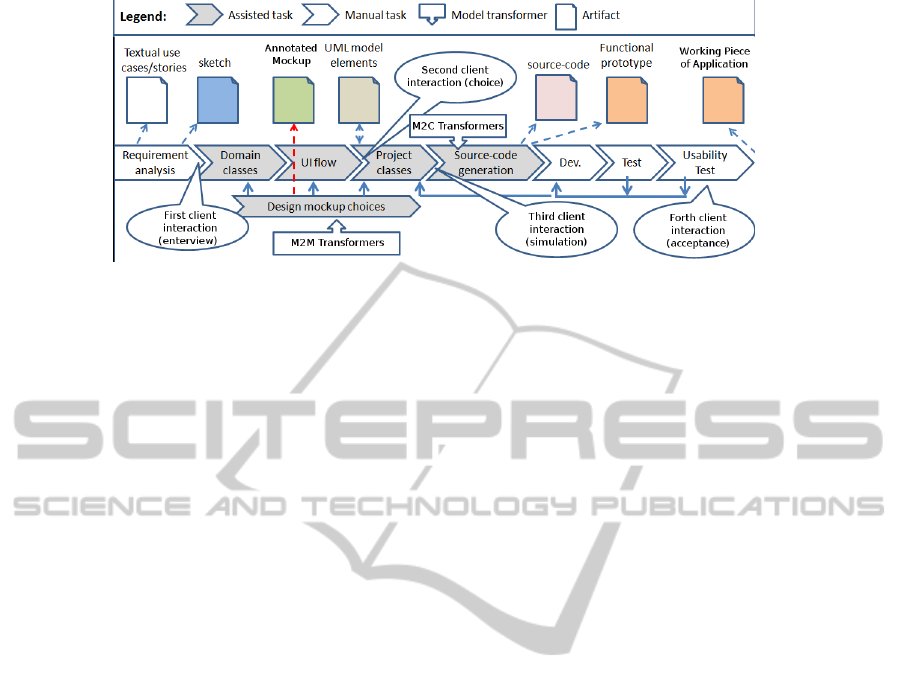
Figure 1: Methodology with Tasks Assisted by Tool, Allowing the Generation of Pre-prototype Models. Notice that it is Used
in Each Iteration to Perform Many Cycles of Validation, Allowing Iterative and Incremental Steps Towards the Development
of Working Pieces of Application.
3.1 Design and Refinement of Mockups
Through simple input model we allow for the gener-
ation of pre-prototypes with model transformations.
UML models and UI components are designed and
changed with support for transformations. In order
to help designers in the transition from sketches to
mockup models, our tool named MockupToME, sup-
ports automatic and guided transformations (Basso
et al., 2012). A sketch is not used as input to the tool,
but an entity defined as Master, that allows generat-
ing preliminary mockup versions, refined until their
appearance to be similar to the sketch. The design is
performed in synchrony with class diagrams, mean-
ing that a modification in a mockup model may imply
in modifications in a set of classes, managed by the
tool.
An example of generated mockup is illustrated in
Figure 2. Using transformation T1, that takes the
class Client as input, it generates a form to create/save
clients. Mockup models are composed of components
decorated with tags and stereotypes and associated
with properties of the class Client. These transfor-
mations are called startup templates. Similarly, as in
some web frameworks, many templates are available
to generate a mockup model: some are used to gen-
erate a mockup based on CRUD forms, other ones to
generate a mockup based on list and filters, others to
generate a report kind mockup, between other vari-
ants (Aquino et al., 2010). It is important to highlight
that startup templates generate a mockup model that
must be refined and detailed. Besides, a mockup must
offer options that allow clients to explore other possi-
bilities. Thus, a default screen is generated by these
transformations.
In such direction, for the acceptance of the
mockup, the client can perform a validation, choos-
ing mockup structures that best fit to his/her needs.
Designing different options for the same mockup
would be a waste of time if designer was not helped
by a tool support. Thus, other transformation tem-
plates can be used to detail a single mockup with
many options. Such characteristic is illustrated in
Figure 2: using T2 and T3 model transformations,
designer can quickly generate UI screens that com-
plement the functionality “create/save client”. Note
that, two different mockup structures for the associ-
ation CreditCard were generated from the transfor-
mations, meaning that clients must decide which of
them to use. Thus, as a mockup can be designed us-
ing different possible UI structures, clients feel more
comfortable to decide for a solution that fulfils a re-
quirement. The usage of model transformers to refine
mockups is a practice that can also be used by other
MDE proposals.
3.2 Pre-prototype Transformation
Templates
Figure 3 expands the tasks between Requirement
Analysis and Source code generation, shown in Fig-
ure 1, and this section systematises such tasks.
3.2.1 Task A: Finding ‘Master’ Entities
Input: Textual use case, Use Case diagram, Class di-
agram, Sketch.
Output: Master entities are included in the textual
use case and related with a Use Case diagram us-
ing a tag. This is required to keep traces between
artifacts.
Description: After a textual use case is elabo-
rated, the model designer analyses the domain
classes looking for those that are characterised
as master entities by the domain-driven design
method (Evans, 2004) and the object oriented
AssistedTaskstoGeneratePre-prototypesforWebInformationSystems
17
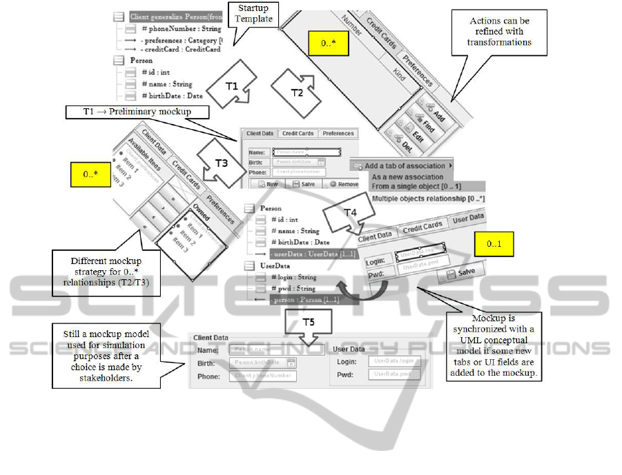
Figure 2: A Mockup Design Started from a Transformation Template T1 that Use as Input a UML Model.
method (Molina et al., 2002). He/she accesses in-
puts from Task A to identify which of the tem-
plates (transformer T1 illustrated in Figure 2) is
more adequate to start a design of UI form.
3.2.2 Task B: Using UI Startup Template
Input: Master entity.
Output: Preliminary mockup model.
Description: Master entities are used as input for
model-to-model (M2M) transformations that gen-
erate a preliminary mockup. Model transforma-
tions allow designer to quickly generate a mockup
model and are classified as startup templates.
Transformation templates owns rules to generate
or modify model elements through annotations, as
shown in Figure 4.
Exemplification: The “Add” button shown on top
right of Figure 2 owns following annotations: 1)
«AddDetail» is an stereotype representing an ac-
tion type to insert Detail instances into a Master
instance; 2) {EntityId=“xyz”} is a tag represent-
ing the master entity; 3) {DetailEntityId=“xyz”}
is a tag representing the detail entity related to the
action. Stereotypes and tags are also used to de-
scribe a UI structure, cf. Credit Card element in
Figure 4.
3.2.3 Task C: Refine UI Options
Input: Preliminary mockup model, Master and De-
tails.
Output: Mockup model with alternative UI struc-
tures.
Description: Detail classes must be identified. The
goal is to find domain classes that drive the de-
velopment of a given functionality; then M2M
transformations are used to generate variants for a
given CRUD. In other words, the screens shown in
Figure 2 can became an independent form, mean-
ing that users can save preferences for persons
without editing person data using a CRUD form,
or they can be part of the same transaction that
saves the data of the entity Person.
Exemplification: The element Credit Card shown in
Figure 4 is totally replaced by another structure
that also allows one to “add or remove” instances
of credit cards to/from a person. Note that, this
element owns the tag {LayoutStrategy = Table-
BarDetailCollection}. This means is specified se-
mantics about mockup implementation. Besides,
one can use transformation templates that changes
these values, modifying structure and semantics.
For example, Figure 2 illustrates a transforma-
tion T3 that is applied in the preferences associ-
ICEIS2014-16thInternationalConferenceonEnterpriseInformationSystems
18
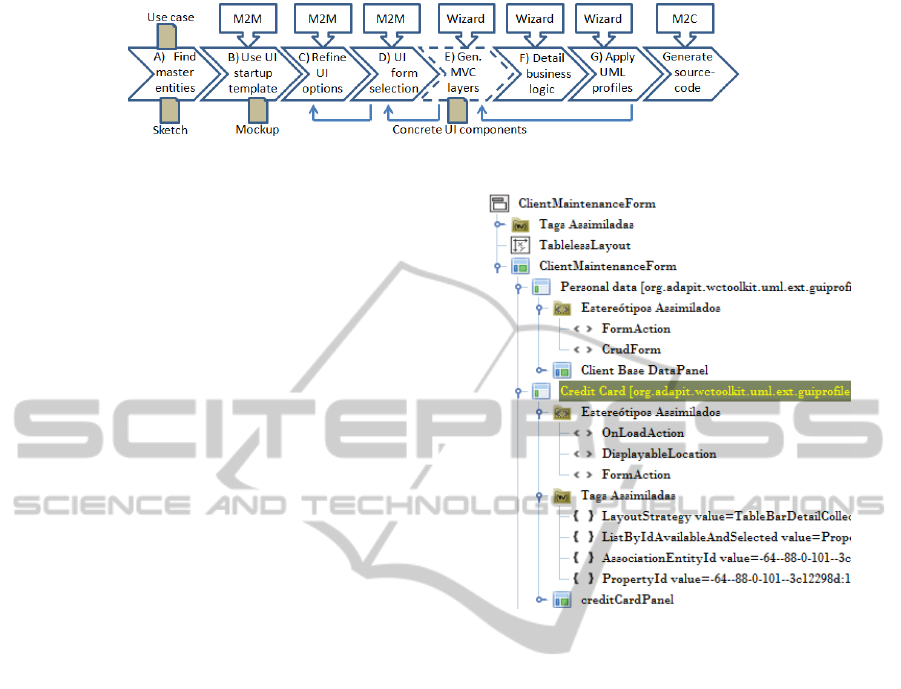
Figure 3: Pre-prototype Design Tasks to the Generated Functional Prototypes Through Transformations.
ation between an entity Preference and an entity
Client, a many to one relationship. This allows
generating a different structure then that gener-
ated by T2, also considering a many to one rela-
tionship whose mockup structural annotations are
presented in Figure 4.
3.2.4 Task D: UI Form Selection
Input: Mockup model with different UI structures.
Output: Menu items, links between user interactions
and mockup model parts.
Description: In this task, the client decides between
options available for the designed mockups.
We developed MockupToME to allow design and
simulation of mockup models considering differ-
ent structures for CRUDs, Form reports, database
filters, amongst others. Using many model trans-
formations, an annotated mockup can be easily
changed. This change can replace mockup ele-
ments by new ones os simply modify the value
of tags and stereotypes to support a different be-
haviour, such as changing a stereotype «Save»
that persist one object by «Merge» that links two
associated objects. This allows to quickly present
a different structure of a mockup while require-
ments are being discovered.
Client Evaluation: Clients can simulate UI flow be-
fore source code is generated, deciding the best
structure for a mockup. In the case of non-
acceptance or corrections in the mockup models,
previous tasks are executed again until the client
decide for a specific mockup structure. In the case
of acceptance, the designer refines the mockup.
Exemplification: Considering alternative structures
that are designed, the mockup model shown in
Figure 4 can have more than one element that rep-
resent the association between Credit Card and
Client. Both representations are modelled and
clients decide which is the best by visualising
mockups inside MockupToME, in a Desktop sim-
ulation.
Final Steps: After client acceptance, mockup is re-
fined. This implies in constraining each form field
Figure 4: Mockup with Annotations.
with validations. Such validations are represented
by annotations and supported by a wizard. Be-
sides, it is required to specify menu items and
other starting points that call the execution of a
given mockup.
3.2.5 Task E: Generating MVC Layers
Input: Mockup model with different UI structures.
Output: Concrete UI models, other Model-View-
Controller (MVC) model layers than not the view.
Description: Once the mockup model is validated
and a structure for a mockup is decided, the pro-
cess towards generating a functional prototype
can be executed. This implies in generating all
web information systems layers considering the
selected domain features. Figure 4 presents a
mockup elements that are used to generate other
layers of the MVC architectural pattern. Some of
these layers are represented with UML (Entity and
Data Access Object) and others with DSM (Con-
troller and View).
Exemplification: The stereotype «AddDetail» as-
signed to the “Add” button implies in the gen-
eration of a specific Event instance. These two
AssistedTaskstoGeneratePre-prototypesforWebInformationSystems
19
model elements, the concrete UI model and the
controller layer, are used in a web server that sim-
ulates the flow of actions on UI screens. In the
case of few adjustments are required, only these
elements are changed by designer. Otherwise,
the generated MVC models are discarded and the
tasks C and D are executed again.
Client Evaluation: Two model elements generated
in this task are important for client evaluations.
A) The first one is the concrete UI model, which
contains abstract elements that are not mapped to
a specific implementation and also contains alter-
native structures. Thus, they are used to repre-
sent general UI components in a computational-
independent model view, given that they contain
annotations. On the other hand, the concrete UI
model is a domain-specific model in a platform-
independent model (PIM) view, since it owns a
single structure and its components are able to
store specific properties that the mockup does not
support, such as events, and layout and appear-
ance properties. B) The second generated im-
portant model element represents the controller
layer, in which component actions/events are de-
fined also as a domain-specific models. These ac-
tions are generated according to the annotations
defined in the mockup model components. Thus,
with these two generated elements, a browser sim-
ulation can be made by clients.
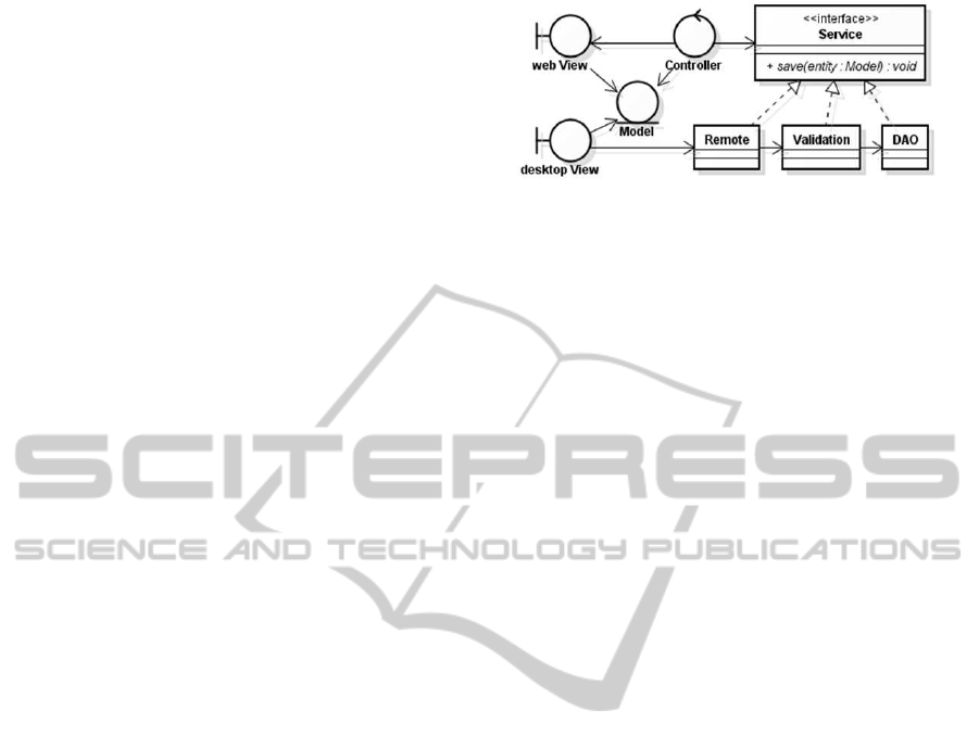
Annotated mockups provide semantic that allow
for connecting generated user interfaces and ap-
plication logic through M2M and model-to-text
(M2T) transformations. For example, mockup
UI components are transformed to other model
application layers as illustrated in Figure 5: a
MVC-based structure owing platform-dependent
UI components (one for web and other for desk-
top), controllers and elements owning application
logic namely Data Access Object. All these layers
are still represented in model, not yet in code, and
require a lot of tags and stereotypes to allow for
the generation of executable source code. These
layers are refined by a software engineer or a de-
veloper and then a new usability test is required in
another iteration cycle.
The MVC-based model layers shown in Figure 5
are used as input for M2C transformations that
generate functional prototype source code. This
was reported in a multi-year industry effort in pro-
ducing model transformations to generate differ-
ent MVC-based structures for different software
projects (Basso et al., 2012). For example, in
some projects it was used only a web platform,
using a common MVC structure, without the Ser-
Figure 5: MVC Multi-Layered Structure.
vice interface and derived classes, while other
projects also included a desktop platform, requir-
ing other structure to implement also remote ac-
cess for an application that run in a web server.
3.3 Generating Functional Prototypes
In this stage the client has already accepted the pre-
prototype models. We consider the correct moment
to detail pre-prototypes to support M2C transforma-
tions. Thus, throughtasks F and G, the focus is in gen-
erating the functional prototype source code that can
be tested in a real world scenario considering database
transactions.
3.3.1 Task F: Detailing Business Logic
Input: Concrete UI components, Controller, Master
and Detail entities.
Output: Data Access Object (DAO) UML Interface.
Description: This task intends to generate other spe-
cific model layers that are mostly mapped to the
data access layer, to constraint controller layer ac-
cess, and to constraint UI fields with security de-
tails.
Exemplification: After Task E, one can con-
straint each concrete UI field to be visi-
ble/editable/enabled only by specific UML Ac-
tors, linking such elements. This activity is sup-
ported by a wizard that allows security constraints
definition. Considering the actions semantics
owned by UI elements, the business logic model
layer is generated as a DAO UML Interface shown
in Figure 6. It is an interface from the UML Class
Diagram in which operations are decorated with
annotations for persistency, database constraint
checking, queries, and so on. Such operations
contain the semantics to save objects and to apply
queries into databases. Thus, they are mapped,
for example, to SQL queries or HQL if the target
technology is Hibernate, during a M2C transfor-
mation that generates source code for operation.
Next step after validating and refining anno-
tated mockups is to generate MVC-based lay-
ICEIS2014-16thInternationalConferenceonEnterpriseInformationSystems
20
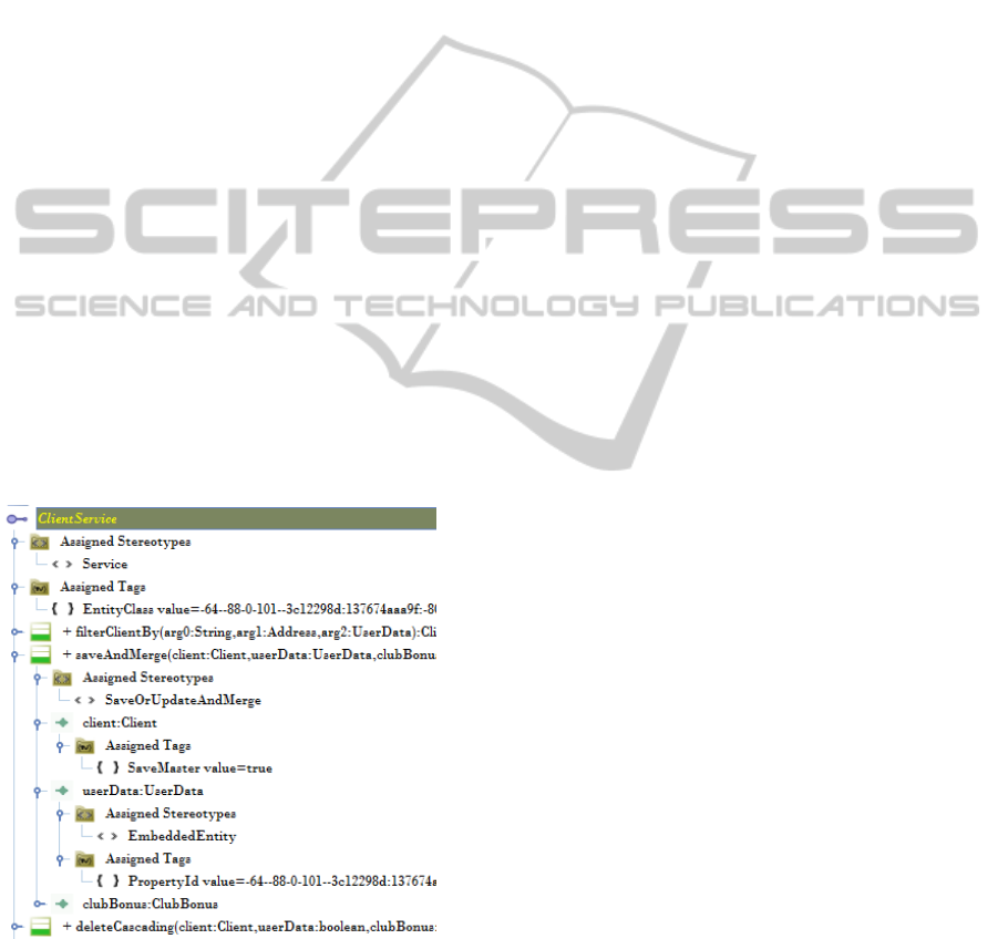
ers as UML models. For example, both one-to-
one strategies imply in two additional parameters
into an operation to persist clients in the service
layer shown in Figure 5. This is exemplified in
the “ClientService” interface shown in Figure 2,
that handles business logic to persist a client.
Thus, this button is stereotyped with «SaveOrUp-
dateAction» and implies in a transformation that
generates an operation named “saveAndMerge”,
shown in Figure 6. The use of different values for
tags and stereotypes on UI components implies in
different signature for this operation. Operation
signatures embedded with application logic that
links to UI components is very hard to find when
specifying these details by hand.
After startup and guided strategies are used and
assuming that the requirement engineer receives a
client approval, the generated MVC-based mod-
els are refined by a developer. It is also required
to transform an annotated mockup to concrete
platform-dependent components. These UI com-
ponents typically do not have annotations because
their meta-classes own properties such as: posi-
tion, layout managers, events, dialog messages,
general form field validations converted to some
regular expression, and so on. This means that
only concrete components may receive informa-
tion about layout managers that satisfy a specific
UI technology, for example, for a web platform.
Figure 6: Screen shot of a Generated Service Layer as a
UML Interface.
3.3.2 Task G: Applying UML Profiles
Input: Domain-Specific Models (Concrete UI com-
ponents and Controller layer), UML (Model layer
and DAO Interface).
Output: Input elements receives more annotations
to allow the execution of platform-independent
model (PIM) to platform-specific model (PSM)
transformations.
Description: This task is optional, since one can
be interested in transform domain-specific input
models into UML models. Besides, aiming at
generating a more complete source code, designer
can specify some details (e.g., annotations) not
generated by previous transformations. For exam-
ple, we use the object relational mapping wizard
to annotate entities, used to generate Java classes
with JPA.
Source code Generation: M2C transformations are
applied over the input elements to map them to the
Java architecture used by the development team.
This transformation enables the generation of a
functional prototype, since all layers are gener-
ated as source code. Afterwards, source code is
refined by programmers and then tested.
Client Evaluation: Finally, the client performs
his/her forth interaction for acceptance test.
Then, improvements and corrections are made
in the generated functional prototype, delivering
a working piece of software, the last software
artifact as shown in Figure 1.
3.4 Generating Source Code
Input: All aforementioned models.
Output: Source code for MVC-based layers.
Description: The result of aforementioned M2M
transformations is a fully testable PIM model
prototype. This is achieved after the use
of PIM model to PSM model transformations.
This means that all strategies used in anno-
tated mockups imply in the use of different PIM
model to PSM model transformations. Cur-
rently, our tool allows for the generation of
source code for following layers: 1) Model-
Entity layer with support of object relational
mapping details; 2) Controller-Business layer
with support for transactions involving the Ser-
vice/Business layer and calls for a remote access
layer; 3) Controller-Persistency layer with DAO;
4) Controller-Actions layer to handle UI events;
5) View layer that is handled entirely by our tool.
4 VALIDATION
The validation of our work is the complete devel-
opment of a web information system with focus
AssistedTaskstoGeneratePre-prototypesforWebInformationSystems
21

on management of financial support for innovation
projects. The development team managed by Com-
pany A (Team 1) used the MockupToMEtool and pro-
posed methodology, whereas the team of Company B
(Team 2) did not use it. Both teams have members
with similar curriculum and developed similar func-
tionalities as subsystems of the same software. Team
1 is composed of: a Scrum Master; a Java developer,
who has been trained for a month; a Tester, and an An-
alyst who designed GUIs and UML models contain-
ing only a clean conceptual model (a class diagram),
also modified by developers along the execution of a
Sprint.
This study allowed us to observe requirements
validation in regard to the proposed methodology.
The overall project initiated in 2010 and finished
in 2011, resulting in the generation of 47 domain
classes, 26 classified as Masters and 22 Master mock-
ups were generated with startup templates (in the task
“Use UI startup template”), designed as CRUD/List
forms. All developed CRUD functionalities required
associations with Detail classes, meaning that each
one should contain at least one refinement (using a
mockup strategy) for master-detail entities. There-
fore, each mockup required the execution of the task
“Refine UI options” during the prototyping phase.
The designed mockups leaded to the generation
of 82% of overall functionalities, divided in: a) 22
classes for controller layer; b) 35 classes to support
the data access object layer with fully embedded busi-
ness logic; c) 35 classes mapped to apply the form
field validation; d) 47 domain classes with ORM an-
notations; e) 56 JSPs generated to support the view
layer, since some of the designed UI screens were
generated in more than one file.
Since some transformations did not generated full
code, some changes were required in the view layer to
modify layout details and to separate cascading style
sheets from JSP code. However, no change was moti-
vated by misunderstanding requirements.
5 LESSONS LEARNED
Our goal in this study was to observe how our
methodology contributes in the development of a sin-
gle system that is developed from scratch considering
a combined use of Scrum and MDE. This experience
allowed us to observe some benefits promoted by this
methodology as follows.
1) To reduce the time between iterations it is nec-
essary to acquire feedback about what is being pro-
duced. Thus, iterations of one week are preferred
to quickly get feedback from pre-prototypes. Short
sprints requires reducing the time available to an-
notate pre-prototype models, meaning that annotated
mockups must be produced quick;
2) A rich set of CRUD templates to generate di-
verse UI structures, besides allowing non-experienced
modelers to be included in MDE-based processes,
also allow the design of annotated mockups with ac-
tion semantics that, for some functionalities, allowed
producing working pieces of software that did not re-
quired changes in code. However, many other trans-
formations must be incremented to allow generating
full code;
3) Pre-prototypes are helpful to ensure the valid-
ity of requirements in pre-development phases, but in
agile-based processes they must be produced quickly,
otherwise too much time is spent in modelling, ham-
pering the combined use of MDE with agile methods.
In this sense, feedback from client must be captured
as soon as requirements are discovered;
4) We noticed that clients feel more comfortable
to opine about requirement validity when experiment-
ing mockup pre-prototypes than visualising UML di-
agrams.
Because our proposal requires the use of trans-
formation templates to generate and refine mockups,
there are some drawbacks as follows.
5) Transformations can fail, meaning that the pro-
posed methodology is only effective if transformation
templates are perfectly working;
6) Client request CRUD structures, or other func-
tionalities, not yet developed as transformation tem-
plates. This requires a manual design of anno-
tated mockups or, due to short iterations, implies
in the development of the requirement without pre-
prototypes. Therefore, this methodology is only ef-
fective if enough transformation templates are avail-
able to design structures used by clients.
7) In MDE, there is the necessity for new incre-
ments in existing transformations. However, litera-
ture lacks in methodologiesto apply evolutivemainte-
nance in these assets, that must be frequently changed
to comport new requirements; even in a running soft-
ware project as was experienced in this case study.
Therefore, it is necessary a methodology to apply test
driven development in model transformation assets.
8) The learning curve required by developers (the
designers of mockups in this experience) to start pro-
ducing working pieces of applications after source
code generation was a problem. In this case study we
compared equivalent functionalities being produced
by agile teams, one using our methodology and tool
support (Team 1) and the other one producing code
manually (Team 2). Team 1 required more time to
finish a sprint (an iteration) in first two months, but
ICEIS2014-16thInternationalConferenceonEnterpriseInformationSystems
22

the rate in delivering working pieces of application
was similar in next three months. Thus, the learning
curve for the suggested tasks can delay the execution
of sprints in first two months.
5.1 Threats to Validity
In the following we depict each thread to validity
that constraint the findings and the lessons we have
learned.
Internal Validity. This study was conducted in
an industrial environment, with developers that have
few knowledge about model transformation and mod-
elling. It is not possible to infer that a higher knowl-
edge of developers would affect the results of this
study.
External Validity.The results reported in this study
cannot be generalised for all MDE approaches, since
the study used a specific Scrum based methodology
assisted by a specific tool. Therefore, we cannot sus-
tain that all model-drivendevelopmentapproaches for
web applications are compatible with Scrum or could
face the same benefits and drawbacks.
Reliability. This work is trustable guarded the
boundary conditions as follows: four participants
with few know-how about our proposal and tools; the
Scrum process adapted to embed the proposed MDE
methodology; the Java related technologies used to
develop web information systems; the MDE support-
ing tool.
6 FUTURE WORK
Due to the necessity to adapt a software development
process based in MDA-techniques to a new process
that included annotated mockups before the genera-
tion of MVC-based layers, this study point to follow-
ing open questions that deserve in-depth researches:
1) A pertinent question that can promote the adop-
tion of MDE-based processes is how to reduce the
learning curve required to execute model transforma-
tions?
It is known that the learning curve can be re-
duced with good instructions. However, we are mov-
ing further by actively assisting transformation tasks
discussed in Section 3, integrating MDE-based tasks
with development tasks using Eclipse Mylyn plugin.
With active support for tasks it is possible to facilitate
and improve the interaction of developer with MDE-
based techniques.
2) Would the existing Process-Centered Software
Engineer Environment (PSEEs) contribute to the ex-
ecution of the discussed set of MDE-based tasks in
another case study?
PSEEs have been proposedin literature as a means
to automate software processes tasks. More recently,
some proposals suggest that PSEEs could be helpful
in executing MDE tasks (Polgár et al., 2009). How-
ever, Matinnejad and Ramsin (2012) surveyed works
related to PSEEs and reported that industry is not us-
ing such solutions due to the inflexibility in execu-
tion. Motivated by the need to change an existing
software process to a new one, our future works will
also explore this question through techniques to tailor
of software process specifications.
These two researches consider mutually exclu-
sive approaches: 1) the first research consider exe-
cution environments preferred by agile practitioners,
since they can use non predictive processes; 2) the
second research consider predictive processes, pre-
ferred by process engineers. Our goal is to identify
which approach is more interesting to be used with
our methodology and tool support.
Finally, we have not presented UML profiles and
meta-models that allow representing artifacts pro-
duced and consumed among model transformation
tasks. Thus, next work will depict transformations
and annotations used to specify and generate MVC
elements taking as input annotated mockups.
7 CONCLUSIONS
This paper presented a new MDE methodology to
generate pre-prototypes through model transforma-
tions. Along the development of some web infor-
mation systems, we noticed that sketches themselves
do not ensure the validity about requirements along
software process iterations, requiring models that al-
low client to evaluate designed functionalities in lev-
els (pre-prototypes) between sketches and functional
prototypes. Such experiences allowed us observe that
the design of pre-prototypeshelps to identify needs of
the clients during requirements elicitation, reinforcing
same conclusions reported by Davis and Venkatesh
(2004); Elkoutbiet al. (2006) and Nunes and Schwabe
(2006).
In order to be used by non experienced designers
and to quickly generate annotated models that can be
executed and validated still in the modelling phase,
our methodology presents following features: 1) It
begins by one specifying annotated mockups, a kind
of pre-prototype whose UI components owns action
semantics; 2) This is supported by model transforma-
tions and a drawing tool, offering different UI struc-
tures to construct diverse pre-prototype models; 3)
AssistedTaskstoGeneratePre-prototypesforWebInformationSystems
23

Clients are allowed to visualise different structures for
a mockup in order to decide which of them fits best
to his/her needs; 4) Client discovers more necessi-
ties when visualising and simulating pre-prototypes,
allowing designers to quickly change requirements
specifications before produce a functional prototype;
5) The methodology allow the combined use of MDE
and Scrum in iterations lasting one week.
Finally, we summarised a recent industrial expe-
rience in the development of web information system
using our proposal. In such experience, the require-
ments validity was ensured through pre-prototype
models, pointing to no change in the source code
motivated by misunderstanding requirements. This
positive result is in conformance with the experi-
ment conducted Davis and Venkatesh (2004) that pre-
sented a number considerably lower of modifications
when applying pre-prototype validations. However,
while such authors suggest to manually design pre-
prototypes, our proposal builds them with consecu-
tive model transformations. Thus, pre-prototypes are
generated with lower effort.
ACKNOWLEDGEMENTS
The research work on which we report in this paper is
supported by FINEP, CNPq, CAPES, FAPERGS, and
the internal Research Programme at UNIJUI Univer-
sity.
REFERENCES
Aquino, N., Vanderdonckt, J., and Pastor, O. (2010). Trans-
formation templates: adding flexibility to model-driven
engineering of user interfaces. In Proceedings of ACM
Symposium on Applied Computing, pages 1195–1202.
Basso, F. P., Pillat, R. M., and Oliveira, T. C. (2012). To-
wards a web modeling environment for a model driven
engineering approach. In In Third Brazilian Workshop
on Model Driven Development, III BW-MDD.
Bézivin, J., Hammoudi, S., Lopes, D., and Jouault, F.
(2004). Applying MDA approach for web service plat-
form. In Enterprise Distributed Object Computing Con-
ference, pages 58–70.
Booch, G., Rumbaugh, J., and Jacobson, I. (2005). The
Unified Modeling Language User Guide (2nd Edition).
Addison-Wesley.
Ceri, S., Fraternali, P., and Bongio, A. (2000). Web model-
ing language (WebML): a modeling language for design-
ing web sites. Computer Networks, 33(1-6):137–157.
Davis, F. and Venkatesh, V. (2004). Toward preprototype
user acceptance testing of new information systems: im-
plications for software project management. IEEE Trans-
actions on Engineering Management, 51(1):31–46.
Deufemia, V., D’Souza, C., and Ginige, A. (2013). Visu-
ally modelling data intensive web applications to assist
end-user development. In Proceedings of the 6th Interna-
tional Symposium on Visual Information Communication
and Interaction, VINCI’13, pages 17–26.
Dyba, T. and Dingsoyr, T. (2009). What do we know about
agile software development? Software, IEEE, 26(5):6–9.
Elkoutbi, M., Khriss, I., and Keller, R. K. (2006). Auto-
mated prototyping of user interfaces based on UML sce-
narios. Automated Software Engineering, 13(1):5–40.
Evans, E. (2004). Domain-driven design: tackling complex-
ity in the heart of software. Addison Wesley.
Forward, A., Badreddin, O., Lethbridge, T., and Solano,
J. (2012). Model-driven rapid prototyping with umple.
Software: Practice and Experience, 42(7):781–797.
Georgiades, M. and Andreou, A. (2012). A semantic for-
malization for use case modeling. In ICEIS 2012 - Pro-
ceedings of the 14th International Conference on Enter-
prise Information Systems, pages 172–175.
Kavaldjian, S. (2007). A model-driven approach to generat-
ing user interfaces. In The 6th Joint Meeting on European
software engineering conference and the ACM SIGSOFT
symposium on the foundations of software engineering:
companion papers, pages 603–606.
Matinnejad, R. and Ramsin, R. (2012). An analytical
review of process-centered software engineering envi-
ronments. In Engineering of Computer Based Systems
(ECBS), 2012 IEEE 19th International Conference and
Workshops on, pages 64–73.
Moe, N. B., Dingsoyr, T., and Dyba, T. (2010). A teamwork
model for understanding an agile team: A case study of
a scrum project. Information and Software Technology,
52(5):480 – 491.
Molina, A. I., Giraldo, W. J., Gallardo, J., Redondo, M. A.,
Ortega, M., and García, G. (2012). Ciat-gui: A mde-
compliant environment for developing graphical user in-
terfaces of information systems. Advances in Engineer-
ing Software, 52:10 – 29.
Molina, P. J., Meliá, S., and Pastor, O. (2002). Just-ui: A
user interface specification model. In Computer-Aided
Design of User Interfaces III, pages 63–74.
Nunes, D. A. and Schwabe, D. (2006). Rapid prototyp-
ing of web applications combining domain specific lan-
guages and model driven design. In Proceedings of the
6th international conference on Web engineering, pages
153–160.
OMG (2013). MDA object management group MDA spec-
ifications.
Planas, E., Cabot, J., and Gómez, C. (2009). Verifying ac-
tion semantics specifications in uml behavioral models.
Lecture Notes in Computer Science (including subseries
Lecture Notes in Artificial Intelligence and Lecture Notes
in Bioinformatics), 5565 LNCS:125–140.
Polgár, B., Ráth, I., Szatmari, Z., Horvath, A., and Majzik,
I. (2009). Model-based integration, execution and cer-
tification of development tool-chains. In 2th Workshop
on Model-Driven Tool & Process Integration (MDTPI),
pages 35–46.
ICEIS2014-16thInternationalConferenceonEnterpriseInformationSystems
24

Ricca, F., Scanniello, G., Torchiano, M., Reggio, G., and
Astesiano, E. (2010). On the effort of augmenting use
cases with screen mockups: results from a preliminary
empirical study. In Proceedings of the 2010 ACM-IEEE
International Symposium on Empirical Software Engi-
neering and Measurement, pages 40:1–40:4.
Risti
´
c, S., Lukovi
´
c, I., Aleksi
´
c, S., Banovi
´
c, J., and Al-
Dahoud, A. (2012). An approach to the specification of
user interface templates for business applications. In Pro-
ceedings of the Fifth Balkan Conference in Informatics,
pages 124–129.
Rivero, J. M., Grigera, J., Rossi, G., Luna, E. R., and Koch,
N. (2012). Towards agile model-driven web engineering.
In IS Olympics: Information Systems in a Diverse World,
volume 107, pages 142–155.
Souza, V. E. S., Falbo, R. D. A., and Guizzardi, G. (2007).
A UML profile for modeling framework-based web in-
formation systems. In 12th International Workshop on
Exploring Modelling Methods in Systems Analysis and
Design EMMSAD ’2007, pages 153–162.
Stary, C. (2000). Contextual prototyping of user interfaces.
In Proceedings of the 3rd conference on Designing inter-
active systems: processes, practices, methods, and tech-
niques, pages 388–395.
Vanderdonckt, J. (2005). A MDA-compliant environment
for developing user interfaces of information systems. In
Proceedings of the 17th international conference on Ad-
vanced Information Systems Engineering, pages 16–31.
Vara, J. M. and Marcos, E. (2012). A framework for model-
driven development of information systems: Technical
decisions and lessons learned. Journal of Systems and
Software, 85(10):2368 – 2384.
WebRatio (2013). Web ratio web page.
Yang, F., Gupta, N., Botev, C., Churchill, E., Levchenko,
G., and Shanmugasundaram, J. (2008). Wysiwyg devel-
opment of data driven web applications. Proc. VLDB
Endowment., 1(1):163–175.
AssistedTaskstoGeneratePre-prototypesforWebInformationSystems
25
