
Towards a Method for Combined Model-based Testing and Analysis
Brian Nielsen
Department of Computer Science, Aalborg University, Selma Lagerl
¨
ofsvej 300, DK-9220 Aalborg, Denmark
Keywords:
Verification, Validation, Combined Formal Methods, Applied Formal Methods, Model-based Testing, Static
Analysis, Abstract Interpretation, Model-checking, Simulation.
Abstract:
Efficient and effective verification and validation of complex embedded systems is challenging, and requires
the use of various tools and techniques, such as model-based testing and analysis. The aim of this paper is to
devise an overall method for how analysis and testing may be used in combination to increase the quality of
embedded systems, and reduce development cost. The method is centered on a common verification planning
and iteratively exploiting the established results to strengthen the verification activities. We conclude that the
proposed method is general enough to capture most interesting combinations and workflows, but also that
formulation of more specific combination patterns will be useful to encourage future tool collaborations.
1 INTRODUCTION
The verification and validation (V&V) of complex
embedded systems is a challenging and costly task.
Manufacturers are under a high pressure for deliv-
ering increasingly intelligent and feature rich prod-
ucts with short time-to-market, a high quality, and a
low defect rate. Embedded systems such as those in
the European transport domain (automotive, rail, and
aerospace) must be convincingly demonstrated to sat-
isfy numerous safety, functional, and extra-functional
requirements (Henzinger and Sifakis, 2007). The
costs and efforts needed to accomplish this with cur-
rent industrial V&V-techniques are too high.
Current practices emphasize the use of testing
based V&V. These have well-known limitations such
as cost and effort in developing test suites and main-
taining test benches, low coverage (few sample be-
haviors explored, corner cases difficult to hit), and
is not always systematically applied. On the posi-
tive side they work on larger systems with rich extra-
functional properties, and demonstrate the actual sys-
tem behavior. Generally speaking, testing tends to be
applied late.
In contrast, analysis techniques have great
potentials in being applied early and produce
safe/guaranteed results through an underlying me-
chanical proof thus giving higher confidence and cov-
erage. But these methods are challenged by scalabilty
and learnability. Moreover, they work on (often man-
ually created) models or code abstractions, which im-
plies that the results are valid only on these.
It is a main thesis of the MBAT-project
1
that
significant progress can be reached by the compli-
mentary use and optimized combination of advanced
existing model-based analysis and test (A&T) tech-
niques and tools. However, a simple collection of
individual tools is insufficient, even if they individ-
ually are mature and applicable in an industrial con-
text. Their application must be guided by a support-
ing method. This paper presents our work in progress
towards this challenge.
2 PRELIMINARIES
This section presents the background for the method
work. This includes important terminology and pre-
senting a classification of the main automated V&V-
techniques, and an explanation of V&V-verdicts.
2.1 Verification and Validation
By verification we mean producing objective ev-
idence for deciding whether the system, compo-
nents, or work-products under investigation satisfy
the specified requirements and standards. Validation
1
MBAT (Combined Model-based Analysis and Test-
ing of Embedded Systems) is a European industry led
applied research project under Artemis Grant #269335,
http://www.mbat-artemis.eu/home/
609
Nielsen B..
Towards a Method for Combined Model-based Testing and Analysis.
DOI: 10.5220/0004873106090618
In Proceedings of the 2nd International Conference on Model-Driven Engineering and Software Development (MBAT-2014), pages 609-618
ISBN: 978-989-758-007-9
Copyright
c
2014 SCITEPRESS (Science and Technology Publications, Lda.)

(IEEE, 2004; Jean-Louis Boulanger, 2012a; Jean-
Louis Boulanger, 2012b) is about providing evidence
about whether the system solves the right problem and
satisfies the users actual needs, which may or may
not be accurately reflected in the actual set of require-
ments. Since verification and validation often go hand
in hand, and has many common techniques to evaluate
the system, it is sensible to treat them as an integrated
V&V-activity (Wallace and Fujii, 1989).
Moreover, since the method is also using formal
verification techniques we prefer the term analysis to
denote these, see Section 2.4.
2.2 Model-based V&V
It is believed that the use of models will help de-
fects to be prevented and found earlier, more effi-
ciently, cheaper, and resulting in a higher quality end-
product. A model is an abstract simplified view of re-
ality, in which essential properties are recorded, and
other properties and details irrelevant for the prob-
lem at hand are removed. During design, models
are used for e.g., better communication among en-
gineers, documentation, architecture and behavioral
design and decomposition, design space exploration,
and code/controller synthesis. During V&V, mod-
els support consistency and completeness of require-
ments, verification of system/sub-system/component
behavior and protcols, and test case generation. See
also (Mellor et al., 2003; Estefan et al., 2007; France
et al., 2006; Jean-Louis Boulanger, 2012b).
2.3 Context and Requirements for
Method
The method must work under some basic pre-
conditions. These are:
• It is developed primarily from the perspec-
tive of validation and verification as carried out by
(sometimes independent) verification and validation
teams/experts.
• It must support different abstraction levels rang-
ing from system level, sub-system/control-level, and
component/code level. It must support functional as
well as extra-functional properties like timing, relia-
bility, and performance.
• It must work with a heterogeneous collection of
models and tools. First, there is not a single model-
ing notation that is readily able to capture the above
rich set of properties at all abstraction levels. Sec-
ond, the preferences of modeling notation are not the
same across all domains and industries (e.g., Simulink
in the automotive domain and Scade in the rail and
avionic domains). Even agreeing on a common no-
tation for requirements formalization is problematic.
Thirdly, tools with different verification strengths are
supplied by different tool vendors, and are not in-
teroperable a priory and with semantic variations.
Therefore the presentation here is deliberately agnos-
tic about a specific notations. Thus the required V&V-
evidence is likely to be pieced together from differ-
ent verification steps produced by different tools and
techniques. MBAT will enable interoperation and ex-
change of artifacts and results via a “Reference Tool
Platform” (RTP) also being developed in the project.
• It must be applicable in an industrial context.
This implies that it must be understandable and usable
by industrial V&V-engineers, and advanced mathe-
matical theories must be well hidden. It must fur-
ther be compatible with industrial development pro-
cesses: Although agile and highly-iterative processes
are becoming more used, the V-model is still the main
workhorse and the main reference model.
2.4 Main Automated V&V-Techniques
Overall, V&V can be performed using static tech-
niques or dynamic techniques. Static techniques an-
alyzes the system (or artifacts describing it) without
actually executing it. Dynamic techniques are based
on observing sample executions of the system (or arti-
facts describing it). Figure 1 provides a classification
of the most important techniques investigated in the
MBAT-project, and also points out some well-known
hybrid techniques. See additionally (D’Silva et al.,
2008).
Model-checking is a static technique that algo-
rithmically checks logical properties of a formal be-
havioral model. Given a finite state model (or one
that can be reduced to finite state via abstraction or
symbolic repressentation) of a system and a formal
property, a model-checking tool exhaustively checks
whether this property holds for that model (Baier and
Katoen, 2008). The property may be generic (like
(un-)reachability of states and transitions, or dead-
lock), or user defined safety and liveness require-
ments. Software model-checking is the application of
model-checking directly to programs and source code
(Jhala and Majumdar, 2009). To cope with undecid-
ability and the very large state-space of general and
non-trivial programs, software model-checking often
applies abstraction techniques to the program.
Abstract Interpretation based static analysis is a
method and theory for creating mathematically sound
abstractions of (the semantics of) a program, and us-
ing this abstraction to infer properties about the dy-
namic behavior of the input artifact (normally pro-
MODELSWARD2014-InternationalConferenceonModel-DrivenEngineeringandSoftwareDevelopment
610
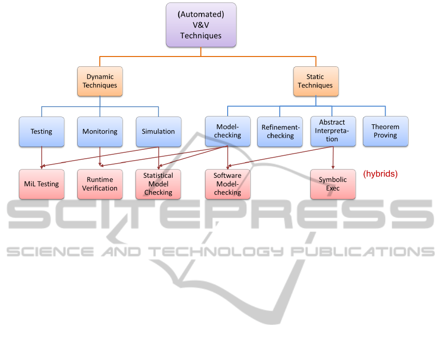
Figure 1: A Classification of Main Verification Techniquess.
gram code). The static code-analyzer algorithmically
computes a sound (over-approximation) abstraction
of the program and checks (typically) generic or in-
variant properties of that abstraction. Static code an-
alyzers are successfully used to prove absence of so-
called runtime errors (e.g., arithmetic overflows, ar-
ray bound violations, division by zero, invalid pointer
accesses), and to infer quantitative information about
the program like worst case stack usage and execu-
tion time. It may also be used to prove user defined
program invariants. However, since abstract interpre-
tation based tools computes an abstraction they some-
times outputs warnings that after further inspection
tourns out to be false-positives.
In symbolic execution a program is executed with
symbolic input variables or constraints rather than
with concrete input data in order to compute the path
condition needed to reach a specific program point.
Constraint solving is then used to check if the com-
puted path condition is satisfiable or not. The pro-
gram point may be undesired (e.g., represents a fault)
or desired (e.g., a statement to be executed by a test
case). That is, symbolic execution has applications
to both software verification and white-box test input
generation.
Testing is a dynamic technique consisting of the
execution of a (software) system under well-defined
conditions (predefined environment/input sequences)
and checking whether the observed behavior deviates
from the specified behavior. In model-based testing,
the aim is to check by execution that the behavior
of implementation conforms to that prescribed by the
specification model. Test case generation tools can
auto-generate valid test cases given a set of test pur-
poses or a structural coverage criteria for the model,
see e.g., (Utting et al., 2012).
Testing without actively stimulating the system
is refered to as passive testing, or monitoring. In
run-time verification formal properties are checked
against concrete runs of the system under test
(Leucker and Schallhart, 2009). Typically the prop-
erties are given as logical formulae or as automata ac-
cepting or rejecting the runs.
Simulation dynamic technique like testing that
consists of the execution of models of (software)
systems under pre-defined inputs with the intent of
checking its dynamic behavior. Based on sample
executions of a model, simulation is used to check
selected properties or inspect parameter dependen-
cies. Simulation is included as a separate main tech-
nique because of its importance for executing models.
When a model-execution is supervised by a test case it
is referred to as model-in-the-loop (MiL) testing. Sim-
ulation may also be used as an under-approximation
mode for model-checkers. Statistical model-checking
(Legay et al., 2010; Bulychev et al., 2012) takes this
further and uses hypothesis testing to make proba-
bilistic guarantees about satisfaction of formal proper-
ties of runs of models with a stochastic interpretation.
There are several additional techniques that shall
not be elaborated here. These include theorem prov-
ing, and well-established manual scrutiny techniques
like Review, Inspection, Walkthrough, or Audits, see
e.g., (Eagan, 1986; IEEE, 1998).
2.5 Verdicts
In our terminology, a V&V-objective is a description
of the capability to be analyzed or tested by a specific
TowardsaMethodforCombinedModel-basedTestingandAnalysis
611
procedure defined in detail as a V&V-case, which
in our case is either an analysis case or a test case
(A&T-case). The objective is typically derived from
a requirement or related to an obligation for verifi-
cation or validation. A requirement may induce sev-
eral V&V-objectives. Dually, a particular V&V-case
may check for more V&V-objectives, but a require-
ment should map to at least one V&V-objective and
one V&V-case.
The outcome of executing a particular V&V-case
is generally one of the four following:
Pass: The analysis or test result adheres to the
V&V-objective. That is, the observation requirement
defined by the objective and A&T-case was success-
fully obtained without any evidence to the contrary.
Fail: The analysis or test result does not adhere
to the V&V-objective. The observed behavior contra-
dicts the required and allowed behavior. Hence, evi-
dence of non-compliance has been identified.
Inconclusive: The evaluation cannot be evaluated
to be pass or fail.
Suspect: Suspicious behavior has been identified
during execution of test or analysis that makes the re-
sult untrustworthy. It may also be caused by a prop-
erty that has been particularly hard to verify. In any
case, a need for additional V&V has been identified
by new A&T-cases.
A reason for an inconclusive verdict is that the de-
sired observation from a test-case cannot be made due
to non-determinism in the system, a failure in the test
harness, or unacceptable execution time. Further, a
formal analysis may have a “Possibly-satisfied” (or
a “Possibly-not satisfied”) outcome, caused by the
over- or under-approximations of system behavior
sometimes made by analysis tools to make analysis
decidable or more efficient.
3 THE OVERALL METHOD
3.1 Combining Analysis and Testing
Consider a given level of abstraction (system, sub-
system or component-level), the V&V will be con-
ducted using a combination of analysis of models and
of code, and testing of models, code and integrated
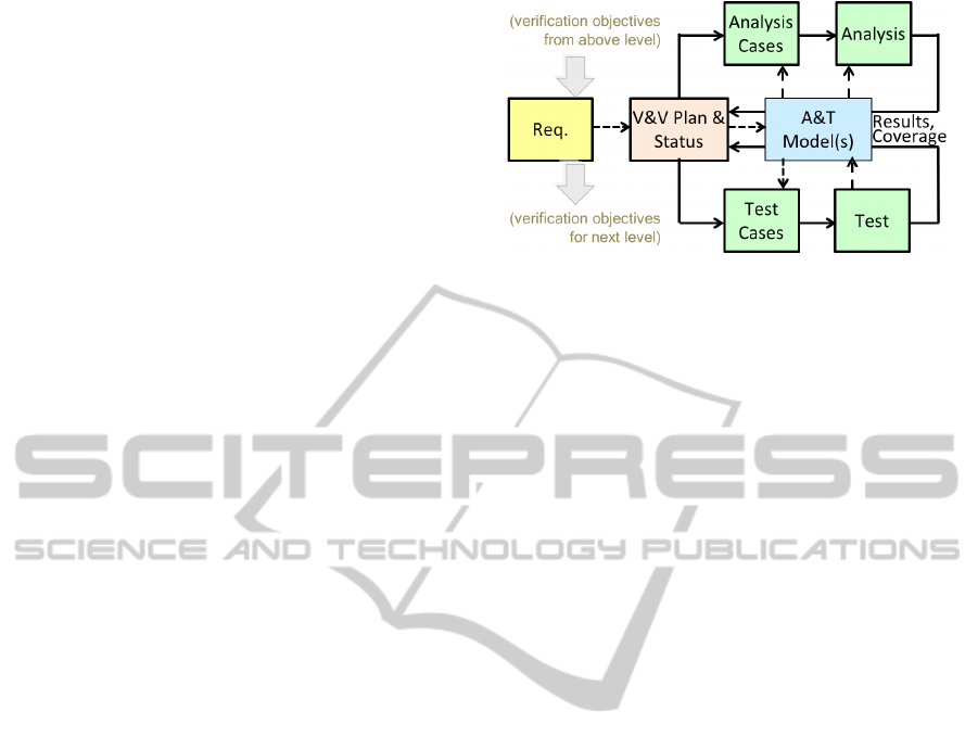
systems. The overall method is depicted in Figure 2.
It operates with two main principles.
The first principle is the establishment of a com-
mon verification plan. This is inspiried by hardware
verification (Foster et al., 2006) that seems to be more
advanced in combination of analysis and testing that
the current practice in embedded software develop-
ment. A verification plan includes a framework for
Figure 2: Overall Method.
specifying requirements and derived verification ob-
jectives independent of the actual verification tech-
niques used to verify them, and of common assump-
tions about the evironment of the considered sub-
system. It also includes a mechanism for tracking the
verification status for each objective (i.e, verdicts and
confidence in the results). It is a thesis that when all
objectives have been successfully verified with the re-
quired confidence, that sufficient “evidence” has been
produced to conclude that the system is correct. A re-
quirements verification matrix (RVM) (Engel, 2010)
developed during initial V&V-planning may serve as
a starting point for more refined planning. An RVM
specifies how (by what verification method and by
what procedure) and when (at what point in the life-
cycle) each requirement will be verified.
The second principle is to exploit the results ob-
tained from one verification step to initiate or improve
a planned subsequent step. This is captured in the
feedback loop in Figure 2 from a verification step (via
the A&T-model) to the verification plan.
Figure 2 also shows that verification objectives
may be propagated from one abstraction level to the
next. Results established by verification at a lower
level, can be used as an assumption when consid-
ering models at a higher level. Similarly, simplifi-
cations, abstractions made at a higher level must be
justified through modeling, testing, and verification
at lower levels. For example, worst-case execution
time (WCET) analysis of the code at the implementa-
tion level is needed to perform schedulability analy-
sis and task allocation optimization at the sub system
level, which again is necessary to establish system
level end-to-end timing properties. Also a simplifi-
cation of the functionality of a component in a model,
may need to be complemented by proving an invariant
of the component refinement.
We have tried to capture an assume-guarantee
style thinking behind the method, but we have also
found no formal framework that is directly applicable
in industry because it is extremely difficult to come up
with usable proof-rules and assumptions (Namjoshi
MODELSWARD2014-InternationalConferenceonModel-DrivenEngineeringandSoftwareDevelopment
612

and Trefler, 2010; Kharmeh et al., 2011).
Thus the main steps of the overall method are:
1. The requirements, assumed to be refined to fit the
given level of abstraction, are inspected and used
to formulate verification objectives. These are
partitioned into sub-sets that should be checked
by model-analysis, testing, and static code analy-
sis using the most suitable technique for that ob-
jective.
In general our recommendation is to perform anal-
ysis first, and use testing for what cannot be ana-
lyzed. The main argument is that analysis is typ-
ically applicable earlier, and gives higher confi-
dence in the results. However, this must be bal-
anced against the criticality and complexity of the
underlying requirement and system, and the effort
that may be needed to perform formal analysis us-
ing a particular technique and tool versus applying
testing (more critical and complex requirements
suggest analysis). Making the right decision re-
lies of insights by the V&V engineer. In addition,
there are often functional and extra-functional re-
quirements that cannot be checked on the model
level, because the model is not rich or detailed
enough - e.g., one cannot verify timing on a model
that is purely functional.
2. From the requirements and other engineering ar-
tifacts available, a model is constructed for the
V&V task at hand. It is not trivial to make a
good model that is understandable, accurately and
truthfully captures the behavior needed to deter-
mine the selected V&V-objectives, and contains
no irrelevant details (Mader et al., 2007). Further,
it should also be traceable such that each struc-
tural element of a model can be explained and ei-
ther maps to an aspect of the component under
modelling, encodes some implicit domain knowl-
edge, or represents an explicit assumption.
3. After identification of the V&V-objectives and
model-construction, the specific analysis or test
cases are formulated (or generated), and the re-
specive analysis or test step is executed to obtain
results.
4. The results include a verdict for each analysis or
test case together with log-files, computed met-
rics, traces etc. Inspection of the results may
cause different actions depending of the outcome.
If the verdict is pass, it is assumed that the V&V-
objective is verified and sufficient evidence is at
hand to reasonably conclude that it is satisfied
and no further V&V for that is necessary. If
the outcome is fail, corrective actions are needed:
identify cause for discrepancy, and correct all im-
pacted artifacts. Possibly further V&V-objectives
need to be formulated to rule out further similar
defects. If the result is inconc the V&V-objective
(or underlying requirement) needs further checks,
e.g., by alternative techniques or alternative tools
(e.g., simulation, testing, or manual test), or by re-
fining the objective (or requirement) into simpler
sub-requirements. If suspect behavior has been
identified, additional V&V-objectives have to be
formulated to identify whether the behavior is cor-
rect or problematic.
5. The V&V plan must be updated with the new ver-
ification status, and a revised plan for the changed
items must be made. The procedure is iterate until
the V&V-engineer has reached the required confi-
dence level.
There are a number of ways where one (test or
analysis) verification step may benefit from results es-
tablished by another (the exploitation feedback loop).
Some (non-exhaustive) examples are:
Under-approximation: Use (under) approxi-
mate techniques like simulation or statistical model-
checking for the objectives where it turned out that
full analysis is infeasible.
Coverage Completion: Initially test suites are
constructed to cover the requirements (e.g., at least
one test per requirement). Test cases may also be
generated based on (potentially stochastic) simulation
executions of a model. In either case, the resulting
coverage of the model (as measured by a structural
coverage criterion like branch or state-coverage) may
be too low. In this case a model-checker may be
used to synthesize the test cases for the missing cov-
erage items (Blackmore et al., 2012) by interpreting
the counter example as a test case
2
. Similarly, at the
code level, a path synthesis tool based on symbolic
execution may be used to synthesize the missing test
input vector for a given white-box criterion (Gunter
and Peled, 2005; King, 1976).
Targeted A&T: If a test reveals a defect, it may be
worth the effort to target the problematic component
with analysis due to the bug-clustering assumption.
Similarly, if a defect is identified by (model) analysis,
it may be worthwhile to create additional test cases
for that objective to increase confidence of the imple-
mentation. Also historical defect data and inspection
results may be used (Elberzhager et al., 2012).
Model-warmup: A test run/simulation run re-
vealing an interesting situation (like a failing test run)
should be further analyzed by importing this scenario
to the model-checker.
2
Some MBT-tools use model-checkers internally to
reach a criterion a-priori.
TowardsaMethodforCombinedModel-basedTestingandAnalysis
613

Analyze Test Model: In model-based testing, the
test model is the specification of the test cases, and
the test model must therefore be shown to be valid
according to the requirements. Otherwise invalid test
cases may be generated.
It is not our goal here to enumerate all options,
but to provide a common framework that is able to
capture the most important ones.
3.2 V&V-flow from Requirements to
System
The main V&V-flow across the different levels of sys-
tem abstractions is depicted in Figure 3 along with
the logical relation between models, and typical tech-
niques used to determine these relations.
1) From the requirements, a (formal) specification
model is constructed that reflects the main aspects of
specified behavior. As hinted in Figure 3 the require-
ments model reflects a logical conjunction of the in-
formal requirements. Such a high-level model both
greatly helps in understanding the implications of the
requirements, and in obtaining a complete and consis-
tent set of requirements very early. The consistency
of the model can be checked by animation and visual-
ization, logical satisfiability checks, and other sanity
checks (deadlock, basic reachability, etc.)
2) From this requirement model, the design and
V&V-flow can start; various analysis, test, and de-
sign models can be derived. Ideally, the dedicated
A&T-models are derived through automatic seman-
tic preserving transformations. However, this is not
always possible, but still the manual construction use
information from design models and documents. Also
V&V is sometimes required to be conducted indepen-
dently of the developers. This may then require a de-
gree of independently constructed models dedicated
to V&V; otherwise there is a risk that the same mis-
conceptions that are reflected in the common model
will be used by both teams, and hence will go undis-
covered.
The A&T-models must satisfy (or refine) the re-
quirements: If both requirement and A&T-models are
formalized, this can be done by refinement- or model-
checking (provided language compatibility). Alter-
natively, if the A&T-model is too large or complex,
or if analysis tool support is inadequate, MiL testing
of the A&T-model can be used as a weaker (under-
approximation) technique. The two techniques can be
used in conjunction such that requirements that could
not be decided by analysis can be tested or simulated.
3) The low level design models are typically
richer models and elaborate in detail how (as op-
posed to what is required) each component is going
to function. Logically the relation between the high
level and low level design is a refinement. In princi-
ple it is a relation between two models, so it can be
checked by analysis. However due to richness and
size, it may be necessary to do MiL simulation and
testing, (or combined as indicated above). Due to size
it is often necessary to perform the refinement check
component-wise. From a formal perspective compo-
sitional techniques are highly desirable. Similarly, for
legacy components where no model is available
3
test-
ing may be necessary.
4) The relation between the produced code (man-
ually crafted or synthesized) for a component and
its design model is in principle a refinement, that
can be checked by a combination of techniques. i)
Static code analysis can verify satisfaction of com-
ponent properties like absence of certain runtime er-
rors, and satisfaction of invariants and assertions typi-
cally derived from design or component level require-
ments. Similarly, with additional platform assump-
tions, worst-case execution time and stack consump-
tion can be computed. ii) Functionality is checked
by SiL-testing (Software-in-the-Loop), iii) Directly
model-checking source code (using software model
checking) is an alternative (still mostly research-level)
technique that may be applicable when developed to
an industrial level.
We remark that even when code is automatically
generated from a model that has been thoroughly
analysed there are situations where it should also be
tested, for instance when the code generator is not
sufficiently trusted, or when safety-standards demand
tests to be executed on code-level. The analysis effort
is not wasted, because it still provides much higher
coverage, and thus higher confidence to the manufac-
turer.
5) The integrated system is validated by means of
HiL/Pil (Hardware/Processor-in-the-Loop) testing.
The overall method depicted in Figure 2 may re-
peated at differnet levels of abstraction to support the
V&V-flow outlined here.
4 EXAMPLE APPLICATIONS
The method presented in Section 3 is being adapted
and evaluated by industrial partners through applica-
tion in their respective use-cases. Industry lead use-
case teams with academic partners and tool vendors
3
Model-learning is a technique for extracting models of
observed behavior and thus an approximate automated ab-
straction technique. Currently it is not ready for industrial
use.
MODELSWARD2014-InternationalConferenceonModel-DrivenEngineeringandSoftwareDevelopment
614
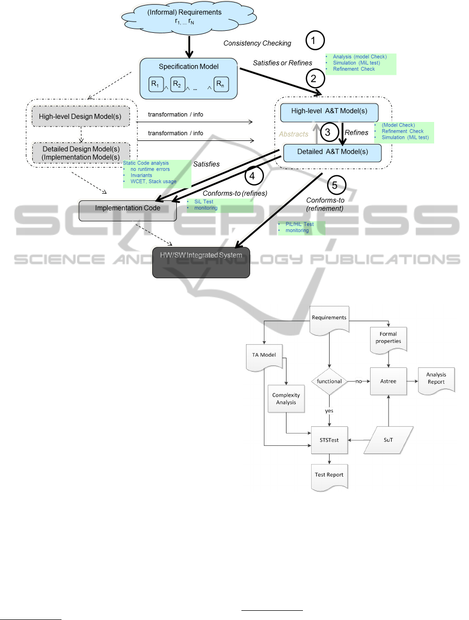
Figure 3: Main V&V-flow.
collaborate to address the challenges defined by the
use case.
4.1 A Hybrid Powertrain Control Unit
Figure 4 illustrates an approach being investigated by
the automotive partner “AVL”
4
in their use case con-
cerning a hybrid powertrain control unit (HCU) that is
responsible for coordinating the energy flows between
engine, electrical motor, and the battery.
In this proposed workflow, the set of requirements
are partitioned into requirements to be verified by test-
ing, and requirements to be verified using static code
analysis.
For the “functional requirements” (in Figure 4
meaning what the HCU should and must to under
given stimuli) a behavioral model in UML Statecharts
is made for the main purpose of using it for test case
generation. The STSTest tool from the technology
provider “Virtual Vehicle”
5
takes the model, a test
purpose (derived from the requirements) and gener-
ates one or more corresponding test cases. Moreover,
test case generation is guided by a complexity analy-
sis of the model with the aim of focusing testing e.g.,
generating more test cases that traverse highly com-
plex model fragments, and to help test data selection.
4
http://www.avl.com/
5
http://www.v2c2.at/
Figure 4: AVL Combination.
The “non-functional requirements” (in Figure 4
understood as absence of runtime errors and guar-
antee of certain safety invariants) are formalized as
assertions for the abstract interpretation based stati-
cally code analyzer Astr
´
ee
6
, which will prove with
certainty that the assertion holds, disprove it, or out-
6
small Astr
´
ee is based on techniques developed by
CNRS/ENS and developed/distributed by the tool vendor
Absint http://www.absint.com/astree/index.htm
TowardsaMethodforCombinedModel-basedTestingandAnalysis
615
put warnings that it may not hold. If a warning is
output, further analysis (typical manual inspection) is
needed to determine the actual status.
Preliminary experiences are promising, and indi-
cate that both V&V-coverage and quality of the SUT
has improved significantly. However, it was also
found that it was difficult to use the static code ana-
lyzer to get positive proofs of all the safety invariants.
If the method were followed further, this would
suggest to extend the the proposed workflow to in-
clude another iteration where additional test objec-
tives are added to further check (by testing) the un-
proven requirements.
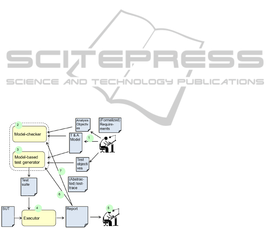
4.2 Exploitation of A&T-results
The method suggests a feed-back loop where a V&V-
result obtained using one A&T-step may be used in
a subsequent one to improve its effectiveness or tar-
get it towards an identified problem. Figure 5 shows
another example pattern for how model-based analy-
sis and testing may be combined. The main aim is to
perform model-based testing to check that an actual
hardware/software system under test (SUT) conforms
to the behavior specified in the test model. The work
pattern proposes to:
Figure 5: A Combined Test and Analysis Pattern.
1. The V&V-engineer creates the A&T-model cap-
turing the designated set of (potentially formal-
ized) requirements. Also he derives a set of test
objectives (a.k.a test purposes) that are mandated
to be checked by one or more test cases. Similarly,
analysis objectives reflect important properties of
the test model.
2. He uses a Model-checking tool to analyze the
test Model. Without a thorough analysis of the
test-model, the test engineer will have low confi-
dence in the behavior of the model (whether it cor-
rectly reflects the requirements) and consequently
whether the generated tests are valid according
to the requirements; test cases generated from a
model are only as good as the model which they
are generated from.
Moreover, if a test case fails, the reason for the
discrepancy is just as likely to be a modeling error
as it is to be a defect in the SUT (or test harness).
If full model-checking is not possible, most
model-checkers support over- or under-
approximations that may be tried, or simu-
lation based verification such as statistical
model-checking could be used.
3. A MBT Tool Generates Test Cases. Ideally,
the MBT tool first generates test cases for the
test objectives (because these reflect requirements
that must be tested), and secondly complements
these with test cases needed to satisfy coverage of
model (specified behavior), and third obtain code
coverage (actual implemented behavior), and fi-
nally complement with long test cases for deep
behavior testing.
4. Once the test cases have been executed, a test re-
port consisting of verdicts and log-files is gener-
ated.
5. The V&V-engineer inspects the test report, and
checks if verdicts, coverage, and logs are as ex-
pected.
6. If a test failed and a defect is identified, or if
the engineer finds behavior in the log that is sus-
picious, it would be valuable to have additional
“similar” test cases generated to increase confi-
dence in that no further defects lie along the trou-
blesome test path. A similar idea is pursued in
(Sharygina and Peled, 2001) but at the level of
code in which a neighbor test case is defined to
be a different branching point in the model cho-
sen along the test case.
7. Another use of a test run (especially a failing or a
suspiciuos one) is to import it into the original test
model, and model-check the analysis objectives
(thus requirements) against the behavior of the
model along this particular trace; this will create
a smaller set of behaviors for the model-checker
to examine, thus reducing state-space explosion,
increasing its success rate, and ultimately confi-
dence in the results. We remark that test models
tend to be larger than the abstract design models
typically used for model-checking, because of the
number of components and data space needed to
MODELSWARD2014-InternationalConferenceonModel-DrivenEngineeringandSoftwareDevelopment
616

reflect the structure and interfaces of the SUT and
its interfaces.
5 DISCUSSION
Systems engineering is “an interdisciplinary approach
and means to enable the realization of successful sys-
tems. It focuses on defining customer needs and re-
quired functionality early in the development cycle,
documenting requirements, then proceeding with de-
sign synthesis and system validation while consider-
ing the complete problem. . . ” (INCOSE, 2013). It
thus concerns all major development steps from prob-
lem definition to systems operation, including V&V.
Our approach shares some aspects like the holistic
view, breaking down, and (initial) V&V-planning, but
focuses on V&V, and specifically the combinations of
analysis and test technique.
In contrast, the B-method (Jean-Louis Boulanger,
2012b; Abrial, 1996; Abrial, 2010) is a specific
“correctness-by-design” formal development method
where specifications are gradually refined towards the
implementation. Specifications at different abstrac-
tion levels are specified using the Abstract Machine
Notation. The B-method is based on set-theory, first
order logic, and substitution rules, and mainly uses
theorem proving techniques to prove properties about
specifications and to prove refinement.
Our work shares idea of using early formal analy-
sis to reduce late testing, but we do not rely on a sin-
gle closed (refinement-based) formal framework, do
not insist on being fully formal, but focus on an op-
timized V&V-flow using complementary strengths of
different verification techniques.
At the research level much effort is spent on push-
ing the boundaries for the size and expressiveness of
the models underlying analysis or testing. Similarly
new automated test generation and execution tech-
niques are being proposed. There is also been an in-
creasing number of research proposals that combines
static and dynamic techniques but in specific settings,
e.g., (Peleska, 2010).
However, what seems to be still missing is an
over-arching method that enables the different tech-
niques to be systematically applied in a combined op-
timizing configuration in an industrial context, which
is the ambition of the research reported here.
6 CONCLUSIONS
Modern embedded systems are so large and complex
that they cannot be cost-effectively verified by a sin-
gle technique, notation, and tool. It is not a question
of whether one should do model-level analysis, code-
level analysis, or model-based testing/simulation, but
how best to use them systematically in an optimized
combination.
It is very challenging to define a common method
that are applicable in industrial practice, but we have
here presented a promising proposal that is cen-
tered around common verification planning and sta-
tus tracking, and iteratively exploiting results of one
procedure to improve the effectiveness of other sub-
sequent ones. The proposed method is currently be-
ing evaluated in context of real industrial use cases
that are gradually applying more and more sophisti-
cated combinations of analysis and testing. The pro-
posed method seems general enough to capture most
interesting combinations and workflows, but we are
working on identifying and formalizing further spe-
cific combination approaches and representing these
as A&T-patterns in the style of Figure 5 that can be
instantiated by particular tools.
ACKNOWLEDGEMENTS
We would like to thank the many MBAT partners
and individuals have contributed to the method work.
In particular, we would like to thank Jens Hermann,
Michael Siegel, Wolfgang Herzner, and Udo Brock-
meyer for their inputs, inspiring discussions and col-
laboration.
REFERENCES
Abrial, J.-R. (1996). The B-book: Assigning Programs to
Meanings. Cambridge University Press, New York,
NY, USA.
Abrial, J.-R. (2010). Modeling in Event-B: System and Soft-
ware Engineering. Cambridge University Press, New
York, NY, USA, 1st edition.
Baier, C. and Katoen, J.-P. (2008). Principles of Model
Checking (Representation and Mind Series). The MIT
Press.
Blackmore, T., Halliwell, D., Barker, P., Eder, K., and Ra-
maram, N. (2012). Analysing and closing simulation
coverage by automatic generation and verification of
formal properties from coverage reports. In Integrated
Formal Methods, pages 84–98. Springer.
Bulychev, P., David, A., Guldstrand Larsen, K., Legay,
A., Mikuionis, M., and Bgsted Poulsen, D. (2012).
Checking and distributing statistical model checking.
In Goodloe, A. and Person, S., editors, NASA Formal
Methods, volume 7226 of Lecture Notes in Computer
Science, pages 449–463. Springer Berlin Heidelberg.
TowardsaMethodforCombinedModel-basedTestingandAnalysis
617

D’Silva, V., Kroening, D., and Weissenbacher, G. (2008).
A survey of automated techniques for formal soft-
ware verification. Computer-Aided Design of Inte-
grated Circuits and Systems, IEEE Transactions on,
27(7):1165–1178.
Eagan, M. E. (1986). Advances in software inspections.
IEEE Trans. Softw. Eng., 12(7):744–751.
Elberzhager, F., M
¨
unch, J., and Nha, V. T. N. (2012). A
systematic mapping study on the combination of static
and dynamic quality assurance techniques. Informa-
tion and Software Technology, 54(1):1–15.
Engel, A. (2010). Verification, Validation, and Testing of
Engineered Systems, volume 84. Wiley. com.
Estefan, J. A. et al. (2007). Survey of model-based systems
engineering (mbse) methodologies. Incose MBSE Fo-
cus Group, 25.
Foster, H., Loh, L., Rabii, B., and Singhal, V. (2006).
Guidelines for creating a formal verification testplan.
Proc. Design & Verification Conference.
France, R., Ghosh, S., Dinh-Trong, T., and Solberg, A.
(2006). Model-driven development using uml 2.0:
promises and pitfalls. Computer, 39(2):59 – 66.
Gunter, E. and Peled, D. (2005). Model checking, testing
and verification working together. Formal Aspects of
Computing, 17(2):201–221.
Henzinger, T. A. and Sifakis, J. (2007). The discipline of
embedded systems design. Computer, 40(10):32–40.
IEEE (1998). IEEE 1028-1997; IEEE Standard for Soft-
ware Reviews. IEEE Standards.
IEEE (2004). IEEE 1012-2004; IEEE Standard for Soft-
ware Verification and Validation, 2004. IEEE Stan-
dards.
INCOSE (2013). What is systems engineering. In-
ternational Council on Systems Engineering
www.incose.org/practice/whatissystemseng.aspx.
Jean-Louis Boulanger, editor (2012a). Industrial Use of
Formal Methods Formal Verification. Wiley.
Jean-Louis Boulanger, editor (2012b). Industrial Use of
Formal Methods From Model to Code. Wiley.
Jhala, R. and Majumdar, R. (2009). Software model check-
ing. ACM Comput. Surv., 41(4):21:1–21:54.
Kharmeh, S. A., Eder, K., and May, D. (2011). A
design-for-verification framework for a configurable
performance-critical communication interface. In For-
mal Modeling and Analysis of Timed Systems, pages
335–351. Springer.
King, J. C. (1976). Symbolic execution and program test-
ing. Commun. ACM, 19(7):385–394.
Legay, A., Delahaye, B., and Bensalem, S. (2010). Statis-
tical model checking: An overview. In Proceedings
of the First International Conference on Runtime Ver-
ification, RV’10, pages 122–135, Berlin, Heidelberg.
Springer-Verlag.
Leucker, M. and Schallhart, C. (2009). A brief account of
runtime verification. Journal of Logic and Algebraic
Programming, 78(5):293–303.
Mader, A. H., Wupper, H., and Boon, M. (2007). The
construction of verification models for embedded sys-
tems. Technical Report TR-CTIT-07-02, Centre for
Telematics and Information Technology University of
Twente, Enschede.
Mellor, S. J., Clark, A. N., and Futagami, T. (2003).
Guest editors’ introduction: Model-driven develop-
ment. IEEE Software, 20:14–18.
Namjoshi, K. S. and Trefler, R. J. (2010). On the com-
pleteness of compositional reasoning methods. ACM
Trans. Comput. Logic, 11(3):16:1–16:22.
Peleska, J. (2010). Integrated and automated abstract in-
terpretation, verification and testing of c/c++ mod-
ules. In Dams, D., Hannemann, U., and Steffen, M.,
editors, Concurrency, Compositionality, and Correct-
ness, volume 5930 of Lecture Notes in Computer Sci-
ence, pages 277–299. Springer Berlin Heidelberg.
Sharygina, N. and Peled, D. (2001). A combined testing
and verification approach for software reliability. In
FME 2001: Formal Methods for Increasing Software
Productivity, pages 611–628. Springer.
Utting, M., Pretschner, A., and Legeard, B. (2012). A
taxonomy of model-based testing approaches. Softw.
Test. Verif. Reliab., 22(5):297–312.
Wallace, D. R. and Fujii, R. U. (1989). Software verification
and validation: An overview. IEEE Softw., 6(3):10–
17.
MODELSWARD2014-InternationalConferenceonModel-DrivenEngineeringandSoftwareDevelopment
618
