
Bio-inspired Active Vision for Obstacle Avoidance
Manuela Chessa, Saverio Murgia, Luca Nardelli, Silvio P. Sabatini and Fabio Solari
Department of Informatics, Bioengineering, Robotics and Systems Engineering, University of Genoa,
Via all’Opera Pia 13, 16145 Genova, Italy
Keywords:
Bio-inspired Framework, Active Vision, Non-rectified Disparity Estimation, 3D Reconstruction, Robot
Navigation.
Abstract:
Reliable distance estimation of objects in a visual scene is essential for any artificial vision system designed
to serve as the main sensing unit on robotic platforms. This paper describes a vision-centric framework for
a mobile robot which makes use of bio-inspired techniques to solve visual tasks, in particular to estimate
disparity. Such framework features robustness to noise, high speed in data processing, good performance in
3D reconstruction, the possibility to orientate the cameras independently and it requires no explicit estimation
of the extrinsic parameters of the cameras. These features permit navigation with obstacle avoidance allowing
active exploration of the scene. Furthermore, the modular design allows the integration of new modules with
more advanced functionalities.
1 INTRODUCTION
Depth estimation from stereoscopic image pairs is a
fundamental problem widely discussed in the litera-
ture. It is necessary to perform complex tasks such
as navigation, scene analysis and interaction with the
environment. However, depth estimation is often af-
fected by restrictions such as stereo calibration and
rectification, noise, high computational demand and
occlusions. Usually, fixed and rectified stereoscopic
or RGB-D systems are adopted because of the re-
duced computational load of the algorithms involved
in disparity estimation (e.g. block matching) and 3D
reconstruction. For example, RBG-D devices like Mi-
crosoft Kinect or ASUS Xtion project a known pat-
tern (Scharstein and Szeliski, 2003) of points on the
scene using infrared light. While this allows for faster
computation, this strategy is heavily dependent on the
scene dimensions and the sensing range is fixed. In
(Grigorescu et al., 2011), a robust closed-loop cam-
era pose and scene structure estimation is performed,
which, though providing good results, relies on recti-
fication and parallelism of the cameras. All of these
solutions are far from being similar to how humans
and animals sense of sight works: moreover, they of-
ten reduce the degrees of freedom offered by the sys-
tem.
In (Klarquist and Bovik, 1998), a foveated vision
system is proposed, which relies on consecutive fix-
ations of scene features in order to estimate a global
reconstruction of the 3D scene: their work, despite
having a variable baseline, explains how vergence can
greatly help in scene analysis and highlights the lim-
itations imposed by rectified systems (e.g. minimum
distance for objects, according to the overlapping re-
gion of the view volumes of the cameras).
Thus, despite its complexity, a vergent system can
often be a desirable choice: it allows for the adjust-
ment of the sensing range and many common tasks
(e.g. object tracking or fixation) can benefit from
the use of such a system. Thanks to the growth of
the computational power of PCs and the advantages
in code parallelisation brought by GPGPU, this ap-
proach has been made feasible on current, consumer-
grade platforms.
Due to these reasons and since the human vision
system copes with the aforementioned limitations,
we have based our work on a bio-inspired approach,
where:
• The orientation of each camera can be adjusted
independently.
• The system structure resembles the modularity of
the human vision system, where different areas
have different purposes and information is com-
bined at upper levels.
• Disparity is estimated using a cortical model of
the primary visual cortex (V1) neurons and their
interactions.
• The 3D reconstruction of the scene is computed
505
Chessa M., Murgia S., Nardelli L., P. Sabatini S. and Solari F..
Bio-inspired Active Vision for Obstacle Avoidance.
DOI: 10.5220/0004873705050512
In Proceedings of the 9th International Conference on Computer Graphics Theory and Applications (WARV-2014), pages 505-512
ISBN: 978-989-758-002-4
Copyright
c
2014 SCITEPRESS (Science and Technology Publications, Lda.)

in parallel with a Single Instruction Multiple
Threads (SIMT) approach.
Following the Early Vision model proposed by
Adelson & Bergen (Adelson and Bergen, 1991),
many steps are necessary in order to gain a deep un-
derstanding of the scene structure, ranging from dis-
parity estimation and 3D reconstruction to image seg-
mentation and blob detection: many solutions have
been devised over the years (Chen et al., 2011), each
of them based on different assumptions and/or with
different strengths, weaknesses and execution times.
In any case, their main goal lies in measuring a spe-
cific feature of the scene.
When approaching the problem of robot naviga-
tion, computer vision is not the only discipline in-
volved: the robot needs to be modelled, all of its sen-
sors have to be analysed in order to characterise its
proprioception (position and orientation estimation)
and interaction with the external world (e.g. cameras
for object detection, tracking and/or avoidance). Fi-
nally, every module has to be integrated with the oth-
ers.
The main contributions this paper provides are:
• Integration of features belonging to the Early Vi-
sion model (e.g. disparity and edges) in a modular
framework which combines them in order to solve
complex visual tasks (e.g. 3D reconstruction in a
vergent system, blob extraction, navigation).
• Development of a SIMT approach towards depth
estimation, starting from disparity computed
through a bio-inspired algorithm.
• Evaluation of the performances (execution times
and depth estimation errors) of such platform
when equipped with the aforementioned bio-
inspired algorithm.
The remainder of this paper describes the proposed
system, the flow of data, the experiments and the ob-
tained results.
2 PROPOSED SYSTEM
The proposed system is represented in the block di-
agram in Fig. 1. It comprises many modules: im-
age acquisition, used to obtain the images from the
cameras and to apply undistorting operations, dis-
parity estimation and 3D reconstruction, segmenta-
tion and blobs extraction, Navigator module, which
combines depth and blob information with the robot
state (RobotModel module) to detect near objects and
avoid them during navigation. Finally, a GUI mod-
ule is present which shows a 3D reconstruction of the
scene in real-world coordinates, allows orders to be
issued to the robot and to set the various parameters
which characterise the system.
Great attention has been paid whilst designing this
framework in order to keep it as modular as possible,
having many pieces of software running at the same
time sharing data, and still being easy to update with
new modules and features.
Image Acquisition and Segmentation. According
to the pinhole camera model (Forsyth and Ponce,
2002), the acquisition module encapsulates all the in-
trinsic parameters of the cameras and the functions
to obtain undistorted stereo images. The system does
not rectify the images, and thus it does not need the
extrinsic parameters of the stereo rig.
In order to implement an efficient colour segmen-
tation module, colour edge detection was applied as a
preliminary step to detect the boundaries between the
observed surfaces. Similarly to other approaches (see
(Chen and Chen, 2010; Dutta and Chaudhuri, 2009))
our implementation performed the following opera-
tions:
• Median filtering, to lessen the effect of noise pre-
serving edges.
• Image gradient computation for every channel,
through a derivative kernel (e.g. [−1,0,1]) or
other operators (e.g Sobel).
• Sum of the norm of the gradients (6 components,
X and Y for every channel) for every pixel. To
provide a faster execution, we chose || · ||
1
, sum-
ming the absolute values of the components.
• Binary thresholding (see Fig. 2, second row) in
order to set the strong edges to 0 and the inner re-
gions to 1. The obtained binary map can be then
easily labelled with blob detection algorithms.
Blob Extraction. Based on the algorithm proposed
by F. Chang in (Chang et al., 2004), component la-
belling was applied through contour tracing: we de-
veloped our own implementation of the algorithm
and a library which has been released under the
LGPL license (OpenCVBlobsLib
1
, originally based
on cvblobslib). The original project was enhanced
both in terms of performance (implementing a multi-
thread algorithm) and functionalities: for example,
blob joining capability was added, allowing to link
many separate regions to one entity. Regarding the
multi thread implementation, the approach can be de-
scribed as follows:
• Horizontal splitting of the image into number of
Threads regions.
1
v1.0 https://code.google.com/p/opencvblobslib/
GRAPP2014-InternationalConferenceonComputerGraphicsTheoryandApplications
506
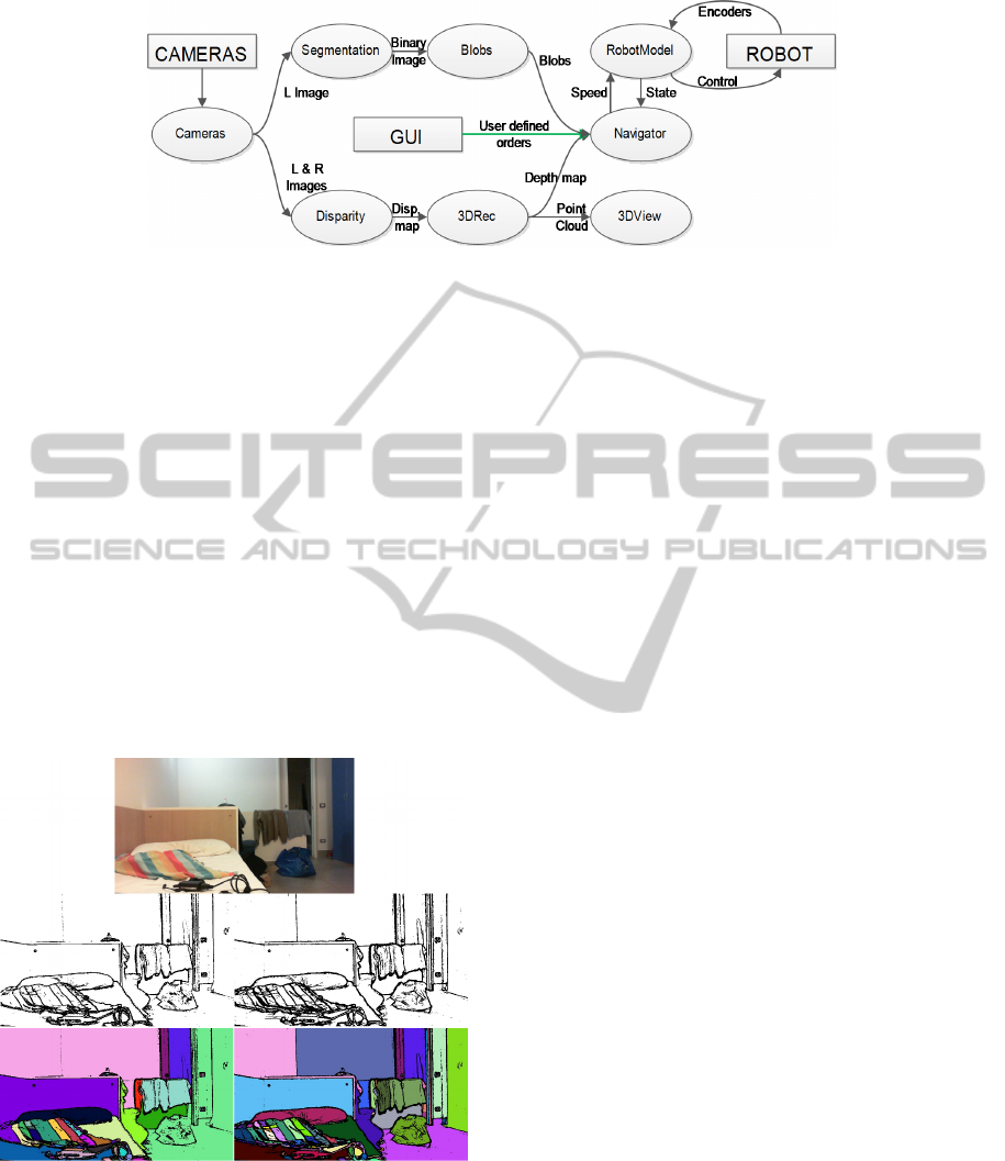
Figure 1: Modules and data flow. Different paths mean parallel tasks.
• Blobs crossing the regions are detected by a single
thread detection algorithm, which runs along the
separating row.
• Having already labelled the crossing blobs, the
other threads can be created and can run in their
image regions without worrying about conflicts
with other threads (that could happen if two or
more would trace the same contour).
• Detected blobs are concatenated in a single array.
Moreover, the library allows to compute geomet-
ric properties of the blobs (joined or not): this is
fundamental after depth estimation, since it allows to
analyse the depth map on a region basis and not per
pixel, enabling the robot to perform coarse scene anal-
ysis for navigation.
Figure 2: Image segmentation and component labelling.
The right pair of images shows our approach (using a 11x11
median filter and threshold value of 21), while the left one
shows the result using Sobel operator. Our implementation
manages to separate more regions.
Disparity Estimation. Disparity, in a vergent
stereo system which purposely loses the horizon-
tal epipolar constraint, is represented by a two-
dimensional vector: this further complicates the
heavy task of its estimation, yet adds a very important
degree of freedom to the vision system, which could
perform better in many tasks (e.g. tracking and at-
tentional mechanisms). Bio-inspired algorithms can
cope well with such two-dimensional disparity vec-
tors: in particular, we have chosen an algorithm based
on the energy model of V1 cortical neurons (Fleet
et al., 1996) (its efficient GPU implementation is de-
scribed in (Chessa et al., 2012)). This architecture is
built on a population of binocular simple and com-
plex neurons, the former implemented as a bank of
complex-valued Gabor filters, with different orienta-
tions in space and phase shifts, the latter as a squaring
operation (energy computation) on the output of the
simple units. Its fundamental processing steps can be
summarised as:
• Linear filtering stage, in which the RFs (Recep-
tive Fields) of the simple S cells are applied to the
image through convolution.
• Energy model, where quadrature pairs of S cells
are combined, squared and eventually thresh-
olded.
• Divisive normalisation, used to remove noise and
to simulate the mechanism of light adaptation.
• Population decoding, in which pools of neurons
responses are combined in order to extract dispar-
ity information.
Although detected disparities are limited in range de-
pending on the radial peak frequency of the used Ga-
bor filters, and on their spatial support, sub-pixel ac-
curacy in disparity estimation is guaranteed, thus cre-
ating very accurate estimates. Moreover, a coarse to
fine approach through a Gaussian pyramid is intro-
duced to further extend the range of detectable dis-
parities while maintaining a relatively low computa-
tional load for the processing system. Given the in-
trinsically parallel nature of our visual neural path-
ways, a GPU implementation of this model is adopted
Bio-inspiredActiveVisionforObstacleAvoidance
507
(Chessa et al., 2012): this dramatically reduces the
time needed for a complete disparity estimation (35×
gain in performance compared to the CPU implemen-
tation using 1024 × 1024 images), opening the door
for real time systems.
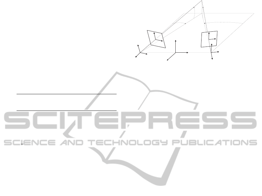
3D Reconstruction. As illustrated in (Chessa et al.,
2009), the cameras and robot reference systems can
be chosen like in Fig. 3, where the 2 cameras are dis-
placed only along the X axis of the robot coordinate
system and their rotations are described with α and β
angles: With this choice, the projective equations for
the left camera can be written as
x
L
= f
0
X
+
cosα
L
+ Z sinα
L
X
+
sinα
L
cosβ
L
−Y sinβ
L
− Z cosα
L
cosβ
L
y
L
= f
0
X
+
sinα
L
sinβ
L
+Y cosβ
L
− Z cosα
L
sinβ
L
X
+
sinα
L
cosβ
L
−Y sinβ
L
− Z cosα
L
cosβ
L
(1)
where f
0
is the focal length of the camera (in cm), α
and β respectively represent the pan and tilt angles,
X
+
= X +
b
2
where b = O
R
− O
L
is the baseline.
With Eq. 1 in mind, assuming that the baseline
and the camera pan and tilt angles are known, the pro-
jection of a point F(X,Y, Z) onto the left image plane
can be computed. Similarly, this process can be ap-
plied to the right camera, by substituting the angles
and changing X
+
to X
−
= X −b/2.
Having obtained a good estimate of the disparity
vector, it is then possible to relate every pixel with its
homologous on the other image. By inverting the pro-
jective equations (considering the world coordinates
as unknowns) a pair of 2 by 3 linear systems is ob-
tained, one for each camera. The left one can be writ-
ten as
(x
L
sin(α
L
)cos(β
L
) − f
0
cos(α
L
))X
−x
L
sin(β
L
)Y
+(−x
L
cos(α
L
)cos(β
L
) − f
0
sin(α
L
))Z
= −1/2x
L
bsin(α
L
)cos(β
L
) + 1/2 f
0
bcos(α
L
)
(y
L
sin(α
L
)cos(β
L
) − f
0
sin(α
L
)sin(β
L
))X
+(− f
0
cos(β
L
) − y
L
sin(β
L
))Y
+( f
0
cos(α
L
)sin(β
L
) − y
L
cos(α
L
)cos(β
L
))Z
= −1/2y
L
sin(α
L
)cos(β
L
)b + 1/2 f
0
sin(α
L
)sin(β
L
)b
(2)
and by itself could not provide a unique solution for
the problem. By combining it with the linear system
relative to the right camera (very similar in structure
to the left one), assuming that F is the solution for
both, a 4 by 3 linear system is obtained.
a
L
a
R
x
L
x
R
y
L
X
L
Y
L
Z
L
X
R
Y
R
Z
R
X
Y
Z
y
R
b
L
b
R
F
O
L
O
R
O
o
L
o
R
Figure 3: Cameras and robot reference systems.
In an ideal case, this system of equations provides
the intersection between the 2 lines starting from the
cameras origins, passing through the points on the im-
age planes and reaching F. However, since dispar-
ity estimation, angle measurements and pixel quanti-
sation introduce errors, these lines may not intersect
at all. Thus, an ordinary least squares solution was
adopted, by minimizing the norm ||A
ˆ
F − b||
2
2
. The
solution is then
ˆ
F = (A
T
A)
−1
A
T
b where
ˆ
F is an esti-
mate of F.
Since each system is independent from the oth-
ers, an SIMT solution was devised and implemented
on the GPU, with different threads handling sepa-
rate linear systems. In this way, VGA-resolution (i.e.
640x480 pixels) images, which involve around 10
5
independent systems, can be easily processed in real
time (10ms in GPU vs 60ms in CPU), transforming
disparity information in depth (see Fig. 4).
Robot Modelling and Control. In order to provide
effective and easy to use controls, the robot was mod-
elled following the unicycle model (Matveev et al.,
2013): thus, two PID controllers were designed to
control linear and angular speed, using the linear dis-
tance and the heading difference as error functions.
The robot state (position, heading direction and
cameras angles) is constantly updated by a dedicated
thread which reads the encoders and computes the
new state for every iteration. In this way, an update
routine runs in the background, supplying the whole
system with a constantly up-to-date state of the robot.
Navigation. Navigation is implemented through
position goals, whose coordinates are taken with re-
spect to the robot starting position and orientation (i.e.
at the start of the program, the robot sets the origin of
the world reference system to its position). In this
step, a first integration of the two streams of informa-
tion is done: segmentation/object information is com-
bined with the depth map in order to analyse it based
on the different objects in the scene, rather than just
by pixel. By checking the central area of the image
GRAPP2014-InternationalConferenceonComputerGraphicsTheoryandApplications
508
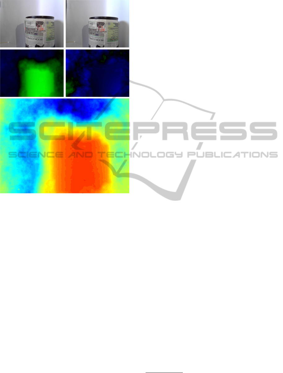
Figure 4: Top row: RGB frames. Middle row: horizontal
and vertical disparities, positive values encoded in blue and
negative in green. Bottom row: Depth map, close pixels
represented by warm colours.
for blobs under a certain depth value, the robot can
detect obstacles, and by evaluating the lateral regions
(see Fig. 5 on the left for the 3 regions) it can effec-
tively set new intermediate waypoints to reach before
its prefixed target. Having detected which of the 2
areas has the furthest objects (i.e. the minimum dis-
tance in that region is greater than in the other one),
the robot proceeds to set an intermediate goal, whose
distance from the robot is proportional to the distance
from the issued target and whose angle (with respect
to the robot heading) has value of ±π/10, with the
sign coherent with which of the 2 lateral regions has
been selected. Moreover, in case the robot finds other
obstacles before reaching its intermediate goal, it will
overwrite it with a new one, thus avoiding the situa-
tion in which a self-generated goal falls over an ob-
stacle.
Thread Execution. A modular system often re-
quires for many operations to be executed simultane-
ously: parallelism is a solution adopted in every bi-
ological system, and has proved itself very effective
in handling multiple tasks. Similarly, our system is
characterised by many threads, some of them created
to follow the data flow pattern and others to provide
constant updates about the state of the robot. We have:
1. RobotModel thread, which communicates with
Navigator, reads the sensors, updates the robot po-
sition and translates orders (i.e. speed) into robot
parameters.
2. Navigator thread, which applies the PID con-
trollers for target-reaching, draws the 2D map,
and generally coordinates the movement process
(e.g obstacle avoidance).
3. GUI thread, which controls I/O with the user and
displays windows.
4. Ogre3D thread, which controls and manages the
3D view window.
5. Main thread, designed to coordinate the whole
data processing.
This last thread, after acquiring the images, imme-
diately creates two child threads, one entrusted with
disparity estimation and 3D reconstruction (compu-
tations that happen almost completely on the GPU),
and the other with colour segmentation and blobs ex-
traction (which takes place only on the CPU). Con-
sequently, every resource the PC can supply is ex-
ploited, thus maximizing the performance. Focusing
on the actual implementation of the system, data is
passed between modules through pointers, when pos-
sible. In this way, unnecessary memory copying oper-
ations are avoided, and the overall performance bene-
fits from this approach.
GUI. With the provided GUI module, the user can
effectively visualise all the intermediate results of
data processing, issue orders, manually set cameras
angles and algorithms parameters and choose one of
the implemented disparity estimation algorithms, if
more than one is present. Moreover, a 2D map shows
the robot position and orientation in real time and al-
lows for order issuing. Finally, a 3D engine renders
the 3D model of the robot, updated in real time, with
the reprojected pixels from the depth map (see Fig. 5).
3 EXPERIMENTAL SETUP
The hardware used in our tests consists of a
consumer-grade PC and a K-Team Koala robot
2
equipped with a pan-tilt module with two off the shelf
webcams and encoders in every motor. All the com-
putations are performed on the aforementioned PC.
2
http://www.k-team.com/mobile-robotics-products/
koala
Bio-inspiredActiveVisionforObstacleAvoidance
509

Figure 5: GUI and 3D reconstruction. From top left: Image with blobs and their mean depth, left and right video streams, 3D
reconstruction. Bottom center: Navigation map and depth map.
Developing a framework for robot control and
navigation requires many sub-systems to be devised,
in order to reach quasi-independence of the soft-
ware from the hardware. To achieve this objec-
tive, we based our work on already established soft-
ware libraries: OpenCV
3
, for image processing, ba-
sic GUI drawing (highgui module) and user I/O,
Pthreads-Win32
4
, for cross-platform (Windows and
Linux) parallel threads management, Ogre
5
, for 3D
self-representation of the robot and reconstruction
of the depth map, CUDA SDK
6
for GPU coding
and OpenCVBlobsLib for labelling and filtering con-
nected regions.
4 TESTING THE SYSTEM ON
REAL GROUND
Firstly, 3D reconstruction was tested to check the ac-
curacy of depth estimation: By placing a planar chess-
board at a known distance we computed the mean
depth over the object area and then compared it with
the real one, obtaining the results seen in Fig. 6.
As for navigation, we performed some experi-
ments in order to assess the actual capabilities of the
robot in navigating in a room:
1. First experiment: Two waypoints were issued
(Fig. 7 shows snapshots taken from a lateral cam-
era). The robot reached the first one avoiding
the frontal obstacle (this was achieved through the
3
version 2.4.6, www.opencv.org
4
ver. 2.9.0, https://sourceware.org/pthreads-win32/
5
ver. 1.8.1, http://www.ogre3d.org/
6
ver. 5.0, http://www.nvidia.com/object/cuda home new
.html
creation of intermediate waypoints by the robot it-
self) and then proceeded towards the second one,
behaving as expected.
2. Second experiment: A single waypoint was is-
sued, the robot found an obstacle immediately in
front of itself and then two others laterally while
reaching its target (Fig. 8).
Videos of these tests and others can be found at
the following link: http://goo.gl/V1hva8. Finally, in
Fig. 9, execution times for a single processing cycle
are shown.
Figure 6: Experimental setup. On the top left, an extract of
the blobs image with their mean depth. On the top right,
a table comparing real (Actual) and computed (Estimated)
distances, along with the standard deviation of depth over
the chessboard area. The error on the estimated depth still
allows for precise navigation.
GRAPP2014-InternationalConferenceonComputerGraphicsTheoryandApplications
510
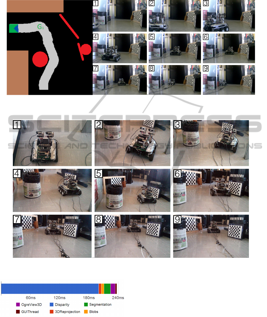
Figure 7: Left figure: Above view of the environment of the first navigation experiment. Three red obstacles and an interme-
diate goal G
1
are present, the brown objects representing other objects. The grey area represents the trajectory followed by
the robot, as drawn by the framework itself. Right figure: Lateral view of the experiment.
Figure 8: Second navigation experiment: back view. The robot found a frontal obstacle and two lateral ones. This time its
goal was set to the position visible in frame 9.
Figure 9: Execution times: note how disparity estimation is
the heaviest computation involved. However, being run on
the GPU, the CPU is free to process other tasks.
5 CONCLUSIONS AND FUTURE
WORK
In this paper a modular stereo-vision based robotic
system has been presented. It has been shown that
even using only consumer-grade hardware, the sys-
tem is able to reach real-time performance with a
good responsiveness of the robot in the avoidance of
obstacles. Also, the biologically inspired approach
has provided good results when dealing with unrec-
tified stereo rigs, providing robustness and reliability.
Moreover, by integrating many features of the image
Bio-inspiredActiveVisionforObstacleAvoidance
511

with the state of the robot, the system is able to pro-
vide an estimate of depth of the pixels and of the 3D
structure of the scene, along with a coarse segmen-
tation of objects based on their colour. By design,
every module of the framework can be enhanced, ex-
panded and more modules can be added: for example,
it could be possible to add information from structure
from motion to enhance the robustness of the vision
module. In the future we plan to add some new fea-
tures such as object recognition and tracking, execu-
tion of tasks when reaching way-points, filtering and
clustering of the 3D reconstruction data. Finally, the
modularity of this work allows it to be used together
with other robotic systems, the only requirement be-
ing the development of a new class modelling the
robot. Thanks to its modularity, we think that other
people could use this framework in their projects and
we plan to release the source code in the near future.
REFERENCES
Adelson, E. H. and Bergen, J. R. (1991). The plenoptic
function and the elements of early vision. Computa-
tional models of visual processing, 91(1):3–20.
Chang, F., Chen, C.-J., and Lu, C.-J. (2004). A linear-time
component-labeling algorithm using contour tracing
technique. Computer Vision and Image Understand-
ing, 93(2):206–220.
Chen, S., Li, Y., and Kwok, N. M. (2011). Active vision
in robotic systems: A survey of recent developments.
INT J ROBOT RES, 30(11):1343–1377.
Chen, X. and Chen, H. (2010). A novel color edge detection
algorithm in rgb color space. In Signal Processing,
2010 IEEE 10th Int’l Conf. on, pages 793–796. IEEE.
Chessa, M., Bianchi, V., Zampetti, M., Sabatini, S. P., and
Solari, F. (2012). Real-time simulation of large-scale
neural architectures for visual features computation
based on gpu. Network: Computation in Neural Sys-
tems, 23(4):272–291.
Chessa, M., Solari, F., and Sabatini, S. P. (2009). A virtual
reality simulator for active stereo vision systems. In
VISAPP (2), pages 444–449.
Dutta, S. and Chaudhuri, B. B. (2009). A color edge de-
tection algorithm in rgb color space. In Advances in
Recent Technologies in Communication and Comput-
ing, 2009. ARTCom’09. Int’l Conf. on, pages 337–
340. IEEE.
Fleet, D. J., Wagner, H., and Heeger, D. J. (1996). Neu-
ral encoding of binocular disparity: energy models,
position shifts and phase shifts. Vision research,
36(12):1839–1857.
Forsyth, D. A. and Ponce, J. (2002). Computer Vision: A
Modern Approach. Prentice Hall.
Grigorescu, S. M., Macesanu, G., Cocias, T. T., Puiu, D.,
and Moldoveanu, F. (2011). Robust camera pose and
scene structure analysis for service robotics. Robotics
and Autonomous Systems, 59(11):899–909.
Klarquist, W. N. and Bovik, A. C. (1998). Fovea: A
foveated vergent active stereo vision system for dy-
namic three-dimensional scene recovery. Robotics
and Automation, IEEE Transactions on, 14(5):755–
770.
Matveev, A. S., Hoy, M. C., and Savkin, A. V. (2013).
The problem of boundary following by a unicycle-like
robot with rigidly mounted sensors. Robotics and Au-
tonomous Systems, 61(3):312–327.
Scharstein, D. and Szeliski, R. (2003). High-accuracy
stereo depth maps using structured light. In Computer
Vision and Pattern Recognition, 2003. Proc. 2003
IEEE CS Conf. on, volume 1, pages I–195. IEEE.
GRAPP2014-InternationalConferenceonComputerGraphicsTheoryandApplications
512
