
A Telerehabilitation System based on Wireless Motion Capture
Sensors
Pedro Macedo
1,2
, José A. Afonso
1
, Luis A. Rocha
1
and Ricardo Simoes
2,3,4
1
Department of Industrial Electronics, University of Minho, Guimarães, Portugal
2
Institute for Polymers and Composites IPC/I3N, University of Minho, Guimarães, Portugal
3
Life and Health Sciences Research Institute (ICVS/3Bs), University of Minho, Braga, Portugal
4
School of Technology, Polytechnic Institute of Cávado and Ave, Barcelos, Portugal
Keywords: Wireless Sensor Networks, Motion Capture, Wearable Sensors, Home-based Rehabilitation.
Abstract: The constant growth of the elderly population in the world creates new challenges and opportunities in
health care systems. New technological solutions have to be found in order to meet the needs and demands
of our aging society. The welfare and quality of life of the elderly population must be a priority. Continuous
physical activity will play an important role, due to the increase of the retirement age. However,
physiotherapy can be expensive, even when the desire movements are autonomous and simple, also requires
people to move to rehabilitation centres. Within this context, this paper describes the development and
preliminary tests of a wireless sensor network, based on wearable inertial and magnetic sensors, applied to
the capture of human motion. This will enable a personalized home-based rehabilitation system for the
elderly or people in remote physical locations.
1 INTRODUCTION
Developed societies nowadays face an emergent and
possibly problematic situation, if not addressed
properly: the growth ratio of elderly population
compared with the total population. This continuous
growth is changing the demographic structure of
societies, with lower birth rates and increasing life
expectancy (Stula, 2012). This demographic change
(Linz and Stula, 2012) imposes new challenges in
order to create services and products for ambient
assisted living (AAL). These products will enable
the creation of better life conditions for the older
generation in their environment by increasing their
self-confidence, autonomy and mobility (Sun et al.,
2009) (Fuchsberger, 2008) (Kleinberger et al.,
2007).
The monitoring of human body movements,
body kinematics, is a growing research field in areas
such as health care, entertainment and sports.
Nevertheless when creating a wireless sensor
network (WSN) to monitor human body motion,
several factors must be taken into account in order to
assure a reliable operation. The authors in (Hadjidj
et al., 2012) describe the technical challenges faced
when creating a WSN for rehabilitation applications
and review existing projects. Several challenges
need to be addressed on these systems, such as the
fixation of the sensor node, energy efficiency
(normally the sensors are energy constrained), the
usually high amount of generated data per sensor
(high sampling rate) and the impact of the human
body on the signal propagation (the wireless signal
propagation suffers from diffraction around the body
and reflection from the body). Human motion
tracking systems are usually classified as either
visual, by the combination of data from several
cameras to achieve a 3D location of the patient’s
body and limbs (Moeslund and Granum, 2001);
(Wang et al., 2003), or non-visual, such as the use of
wearable sensors.
This paper focuses on the non-visual method,
and describes the development of a wireless sensor
network, based on wearable inertial and magnetic
sensors. When compared to a camera strategy, this
method has the advantages of higher flexibility and
mobility, as it can be used in uncontrolled
environments, without lighting and line of sight
concerns (Aminian and Najafi, 2004).
The capabilities and limitations of this kind of
electronic sensors, when applied to the analysis of
the human posture and movements, are highlighted
55
Macedo P., Afonso J., Rocha L. and Simoes R..
A Telerehabilitation System based on Wireless Motion Capture Sensors.
DOI: 10.5220/0004873800550062
In Proceedings of the International Conference on Physiological Computing Systems (PhyCS-2014), pages 55-62
ISBN: 978-989-758-006-2
Copyright
c
2014 SCITEPRESS (Science and Technology Publications, Lda.)
in (Wong et al., 2007). Several authors have also
underlined the high performance of inertial and
magnetic sensors, when applied to body kinematics
measurement. Accelerometers in (Farella et al.,
2008) are used to exploit their capabilities in terms
of body posture recognition in dynamic everyday
life activities. A protocol to measure the upper limb
kinematics using the Xsens MT9B technology was
developed in (Cutti et al., 2007), with the purpose of
measuring its accuracy (through the protocol) during
movements of clinical relevance. The benefits of
physical activity are exposed in (Steffen et al.,
2011), where the authors propose a personalized,
home-based exercise trainer for elderly people. The
captured movements are evaluated and compared to
a prescribed exercise; the purpose is to assist the
user to correctly perform the proposed movements.
The purpose of this paper is to present the
current status of a wireless posture monitoring
system, based on wearable inertial and magnetic
sensors, applied to rehabilitation.
This paper is organized as follows. The next
section presents an overview of all components of
the implemented system. In the third section, the
method of calculation of the orientation angles is
presented. Experimental results concerning a
rehabilitation session are presented in section 4.
Section 5 tackles future work and presents some
preliminary conclusions.
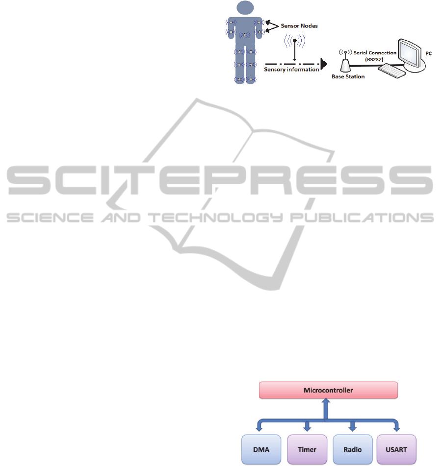
2 SYSTEM OVERVIEW
The electronic system of this posture monitoring
WSN is composed by a base station connected to a
PC and multiple nodes that collect sensory
information from the user. Each sensor module is
firmly attached to one body segment which we want
to monitor. The readings from the inertial and
magnetic sensors are continuously collected and sent
wirelessly to the base station, which forwards them
to the PC through a serial connection. The
information processing in the PC allows the
calculation, in real-time, of the 3D orientation of the
module, expressed by the pitch, roll and yaw angles.
The structure of this system is represented in Figure
1.
Communication between the base station and the
sensor nodes is made using the CC2530, from Texas
Instruments (Texas Instruments, 2009). The CC2530
is a true system-on-chip (SoC) solution for
IEEE 802.15.4 applications (IEEE Std 802.15.4,
2006) which integrates an 8051 based
microcontroller and an 802.15.4 transceiver working
in the licence-free 2.4 GHz frequency band.
Figure 1: System components.
The Enhanced Low Power Real Time (eLPRT)
protocol (Afonso et al., 2011), a MAC protocol that
was designed to optimize the quality of service
(QoS) provisioning and the bandwidth utilization
efficiency, is used to control the communication
through the wireless medium.
2.1 Base Station Architecture
The base station is responsible for coordinating
operation of the wireless sensor network. Its
responsibilities include: associate new sensor nodes
to the network; allocate time slots on the eLPRT
superframe for nodes to transmit; and keep the
synchronization in the network, with the help of the
periodic transmitted beacons.
The base station is powered by the PC, so its
energy consumption is not a concern. The
architecture of the base station is shown in Figure 2.
The USART (Universal Synchronous Asynchronous
Receiver Transmitter) and Radio peripherals are
controlled by the CC2530 with the assistance of the
DMA (Direct Memory Access) subsystem.
Figure 2: Base station architecture.
Figure 3 presents the hardware of the base
station, which is composed by a CC2530EM
(Evaluation Module) attached to a SmartRF05EB
(Evaluation Board), both from Texas Instruments.
PhyCS2014-InternationalConferenceonPhysiologicalComputingSystems
56
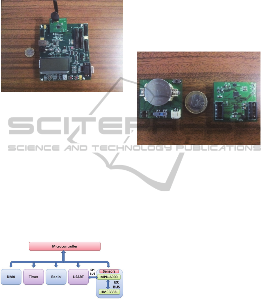
Figure 3: Base station.
2.2 Sensor Node Architecture
The data messages between each sensor node and
the base station are transmitted periodically
according to the superframe period set by the user’s
application. The number of sensor readings in each
period is also set by the user. These multiple
readings are aggregated into a single message and
sent to the base station. Currently a superframe
period of 100 milliseconds and 3 sensor readings is
in use. This gives us a rate of 30 frames per second,
a typical value for motion capture systems (Claypool
et al., 2006).
The sensor board contains 3-axis inertial and
magnetic sensors, which measure variations in the
gravitational and magnetic field forces, respectively.
It is due to these variations that it is possible to
calculate the orientation of the sensor node. The
sensor node architecture is shown in Figure 4.
Figure 4: Sensor node architecture.
The sensory information is collected through the
SPI bus (serial peripheral interface) and sent to the
base station using the eLPRT protocol. Detailed
information about the sensors present in the next
section.
2.2.1 Sensor Node Prototype
The sensor board prototype is illustrated in Figure 5,
with the bottom layer on the left side and the top
layer on the right side. The sensor board is
connected to a CC2530EM module through two
20-pin header connectors.
Figure 5: Sensor board.
There are two sensors present in the sensor
board. The MPU-6000 Motion Processing Unit from
InvenSense, which has an embedded 3-axis MEMS
gyroscope (not used at the moment), a 3-axis MEMS
accelerometer and a digital motion processor (DMP)
hardware accelerator engine with an auxiliary I
2
C
port that interfaces to a third party digital sensor,
such as a magnetometer. The embedded 16-bit
accelerometer has a digital-output triple-axis user-
programmable full-scale range of ±2g, ±4g, ±8g and
16g, a selectable output data rate from 4 Hz to 1 kHz
and a sensitivity of 16.384 LSB/g at ±2g.
The auxiliary I
2
C bus allows the MPU-6000 to
directly access the data registers of an external
digital sensor. In the case of this prototype, the
Honeywell 3-axis Digital Compass IC HMC5883L
is used. Designed for low-field magnetic sensing, it
contains a 12-bit ADC that enables 1 to 2 degrees
compass heading accuracy; with a resolution of
5 milliGauss in ±8 gauss fields.
2.3 PC Software
In the proposed system, the component with the
greatest relevance to the user is the PC application.
This application mediates between the user and the
base station; it can send commands and receive
information sent by the sensor nodes attached to the
body segments. After receiving the data from the
sensors, it calculates the angles of rotation and then
ATelerehabilitationSystembasedonWirelessMotionCaptureSensors
57

presents the movement of the user’s body in
real-time on a 3D model of the human body. The
software provides means to create rehabilitation
session files, where user information and motion
angles are stored. These session files can later be
employed to evaluate the user’s progress. The
referred application, Figure 6, was created in the
object-oriented programming language Java, due to
its portability between operating systems.
Figure 6: Application interface.
One sensor node per monitored segment is
necessary to measure the movement, with three
degrees of freedom (DOF), expressed by the Euler
angles pitch, roll and yaw. The complete model
consists on fifteen rigid body segments: pelvis,
torso, head, upper arms, forearms, hands, upper legs,
lower legs and foots; connected by virtual joints.
The implementation of this model was made
using the Java OpenGL (JOGL), which is a wrapper
library that allows OpenGL to be used within the
Java environment.
The system was designed to be as intuitive and
easy to handle by the user as possible. There are two
main components to take into account, in order to
have the system in full operation mode: the
configuration of the network (configuration of base
station and sensor nodes), started automatically by
the program when the Start button is pressed; and
the calibration of the sensor nodes, that is, the
process of finding orientation and placement of the
multiple sensor nodes attached to body segments.
These components are described in the next section.
2.3.1 Configuration and Calibration
Within the application folder, there are two
configuration files of utmost importance:
Configuration File: Herein lay the configuration
parameters of sensor registers present in the
sensor board. Although there is a default
configuration stored in the CC2530
microcontroller, which is then loaded to the
sensors, the configuration parameters can be
altered, maybe not by the end user, but by a
medical specialist (physiotherapist) at the
beginning of the treatment.
Calibration File: This calibration file
corresponds to maximum and minimum values
of the accelerometer and magnetometer readings.
These values are compared to the actual readings
of the sensors, for normalization, producing
outputs in the range of -1 to 1, as in ‘g-forces (in
the case of the accelerometer, this happens when
no external force besides gravity is present). One
calibration file for each sensor node in the
network is required, since not all the sensors give
the same readings. This file is generated by a
different application. For a better functionality of
the system, this calibration should be done at the
operation location.
2.3.2 Program Execution Steps
In the application’s main window, shown in
Figure 6, there is a Start button that, when pressed,
initiates the configuration of the system. The
configuration is divided in the following steps:
Serial Port Detection: The connection between
the PC and the base station is made through a
serial port interface, so at this point is
fundamental to determine which COM port is
associated to the base station. To achieve this,
the application starts by discovering all the COM
ports available in the PC, and then sends a
command through them. The COM port which
answers according to what is expected is the port
connected to the base station. This process
enables the user to use any available port in the
PC, which is important with equipment such as a
laptop, where USB to serial converters are used.
Open Configuration File: Opening the
configuration file and saving its parameter values
(sensors registers) on the application. This file is
common to all the sensor nodes in the network.
The superframe period and number of samples
per period are also configured here. These two
parameters combined give us the sampling rate
of the sensor readings.
Configure Superframe Period in the Base
Station: A command containing the superframe
period is sent to the base station. Immediately
after receiving this value, it starts sending
beacons at that interval to the network. These
beacons allow the synchronization between the
PhyCS2014-InternationalConferenceonPhysiologicalComputingSystems
58

sensor nodes and the base station.
Turn on the Sensor Nodes: A notification
message appears at the application’s main
window, alerting that the sensor modules can be
turned on by the user. When activated, the sensor
node will become associated to the base station.
After that, the base station allocates a time slot in
the superframe, according to the eLPRT
protocol, for the sensor to transmit the data.
Acquire Associated Nodes Information: A
command message is sent to the base station,
enquiring for the number of associated sensor
nodes and their respective physical address.
Configure Sensor Nodes: After the discovery of
the physical addresses of all the nodes in the
network, the application sends the configuration
of the sensors registers, superframe period and
number of samples to each sensor node (through
the base station).
Data Acquisition: Since the sensor modules are
now configured, the application sends a start
command message to the base station, for the
sensor nodes to begin their readings at the
defined sampling rate. The base station
broadcasts the message to the network.
The Stop button sends a command to stop data
acquisition at the sensor nodes. After that, the link
between base station and application is closed.
After these steps are executed, it is necessary to
discover the orientation of the sensor nodes (Section
2.3.3) and their body placement (Section 2.3.4). This
is achieved by pressing the Calibration button. This
action leads to the appearance of the Calibration
window. Note that after a calibration is performed,
these orientation and body placement values are
stored in a file. The purpose of this setting is to
facilitate the modules configuration by the user, who
can get the stored configuration by pressing the Last
Know Configuration button (Calibration window).
2.3.3 Node Orientation Discovery
The wireless sensor nodes are attached to the body
segments with Velcro straps, always with the
antenna opposed to the body, in order to minimize
the body effects in the wireless propagation signal,
and placed sideways when attached to legs or arms.
Firstly, the user is asked to stand up straight and
be still, as depicted in the 3D model, for a period of
time. During that amount of time, the API of the
application is collecting raw data from the sensor
nodes and through them calculating the Euler angles.
The estimation of the pitch and roll angles is made
using the gravity component obtained from the
measurement of the accelerometer, while the yaw is
determined from the measures from the electronic
compass unit (magnetometer).
The three coordinate rotations in a determined
sequence describe the orientation of the module; the
rotations of the Euler angles are discussed in
Section 3. Once the final rotation matrix is
calculated, it is multiplied by the gravitational vector
(0,0,1) in x, y and z coordinates, respectively. This
multiplication gives the weight of the module
orientation on each axis. With this weight and the
normalized raw values of the sensors, the orientation
of the sensor node in the body segment can be
determined.
Since there is no offset calculation on the axis, it
implies that the module will always be considered to
have the calculated axis with more weight facing the
gravity, when considering its maximum value (+1g).
This can be problematic if the sensor node is not
attached correctly to the chosen body segment; to
tackle this issue, offset calculations will be
introduced in the future.
2.3.4 Body Segment Discovery
The process of finding the location of the sensor
nodes on the body starts immediately after the
application concludes the orientation discovery
process. A set of instructions (info messages) are
given to the user, with the intent of guiding him
through the procedure of determining the placement
of the sensor nodes attached to the body. These
guidance instructions consist of leading the user to
make specific movements that allow the application
to recognize the corresponding movements for each
sensor node installed. Take for instance the case
where only two sensor nodes are installed. When
rehabilitating the arm, with the modules in the upper
or lower member (forearm), the user is asked to
move the forearm. Then the application detects
which has the largest variation of movement. Even
with a small movement, this is valid. The segment
detection for the leg uses the same principle.
3 ANGLE MEASUREMENT
The accuracy of the sensor nodes, after on-site
calibration, is limited by the sensor’s noise, which
adds to the system a measure of 1 degree error.
Adding to this, it is known that accelerometer
readings are influenced, not only by gravity, but also
from acceleration during the motion of the body.
ATelerehabilitationSystembasedonWirelessMotionCaptureSensors
59
This type of acceleration is not desirable, because it
induces errors at the time of converting raw data
from the sensors into angles. To tackle this problem,
a compensation algorithm is applied to the
accelerometer. Each accelerometer reading is
composed by three values (one for each reading
axis). If no linear acceleration is present (only the
gravitational component), the vector magnitude must
always equal to 1g. If this magnitude is not unitary
under a certain tolerance, meaning that the measure
contains linear acceleration besides gravity, a
compensation algorithm is initiated. This algorithm
uses the values from the current and previous
magnetic readings to compensate for the linear
acceleration errors. This method consists on using
two consecutive magnetic readings (previous and
current) to evaluate their angle () and axis of
rotation (axis), as shown in equations 1 and 2. The
calculation of the angle and the axis of rotation,
allows the rotation of the previous gravity vector to
its new orientation (Dunn and Parberry, 2011).
⋅
(1)
(2)
The smallest angle between the two vectors
(normalized previous and current magnetic readings)
is provided by the dot product seen in equation 1.
This equation is valid since the magnitude of the
magnetic vector is unitary. The cross product
between those two vectors, equation 2, results on the
rotation vector, around which the previous
acceleration vector (gravity vector) is rotated.
The three angles that describe the orientation of
the sensor nodes are obtained using the equations 3,
4 and 5 respectively. The calculus of Pitch and Roll
use the variations of the normalized accelerometer
vector on each axis (a
x
,a
y
,a
z
). Yaw angle is obtained
using only the horizontal components (
,
) of
earth’s magnetic field, previously calculated.
(3)
(4)
(5)
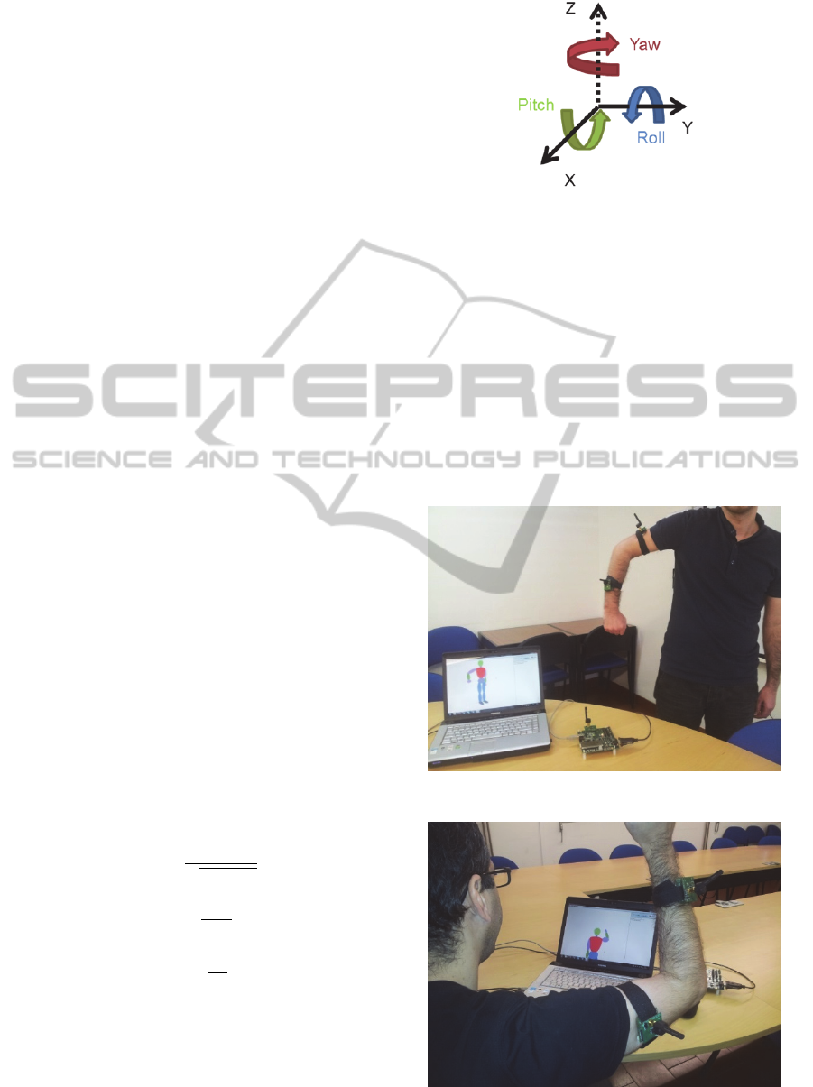
The right-handed coordinate system was used to
calculate the three orientation angles, as shown in
Figure 7. The forward orientation of the module is
set to be along the y axis, with the pitch defining the
rotation on the x axis, the roll on the y axis and the
yaw on the z axis.
Figure 7: Right-handed coordinate system axis
representation.
4 EXPERIMENTAL RESULTS
Experiments were carried out to test the developed
system. One of them had two sensor nodes attached
to the right arm (upper arm and forearm). The goal
was to verify the replication of the body movement
in the 3D model present in the application. Figure 8
and Figure 9 exemplify these experiments by means
of photographs taken while the movement was being
executed.
Figure 8: Right arm movement replication, first position.
Figure 9: Right arm movement replication, second
position.
PhyCS2014-InternationalConferenceonPhysiologicalComputingSystems
60
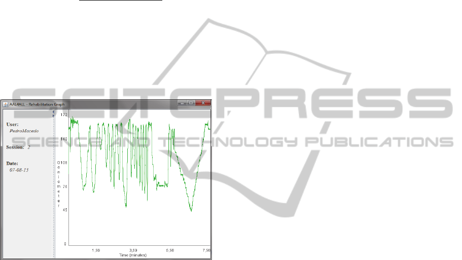
In order to simulate a rehabilitation session, a
second test was performed. The purpose was to
measure the angle between the upper and forearm.
The user was requested to do a simple movement,
flex and extend the arm, multiple times. The angle
() between two joint connected body segments, in
this case upper arm and forearm, is calculated using
equation 6.
⋅
(6)
At this point, the application only deals with
rehabilitation in both arms and legs, with two sensor
nodes in the network. Figure 10 is a draft of what is
desired in a session file. The wave variations seen on
the right side reflect the angle variation (in degrees)
between the body segments over time.
Figure 10: Rehabilitation application draft interface.
5 CONCLUSIONS AND FUTURE
WORK
This paper describes early studies of the design and
development of a wireless sensor network, based on
wearable and easily placed inertial and magnetic
sensors, when applied to physical activities. A Java
application capable of collecting data from the
sensors and present them in a real-time 3D model of
a human body is under development, with the aim of
assisting elderlies in the practice of physical activity.
At this stage, only the motion capture system
capabilities can be evaluated. The displayed Java
application does not transmit any kind of movement
feedback; merely reproduces the executed motion.
The main goal of this project consists in developing
a home-based rehabilitation system that, through
constant monitoring of the movement, is capable of
interacting in real-time with the user. The objective
of this interaction is to assist the user to perform the
prescribed exercise correctly. Poorly executed
exercises can delay the rehabilitation process, or
even cause more damage. Thus, medical specialists
(physiotherapists) should take into consideration
physical limitation of the clinical subject in the
preparation of physiotherapy sessions, and set well-
defined objectives with regard to patient outcomes.
As future work it is intended that the patient,
while doing the prescribed exercises at home,
receives feedback from the application about the
correctness of those movements. Also, future work
includes inserting more sensor nodes in the network,
in order to obtain (simultaneously) the angle
between several joint connected segments, thus
allowing better assessing the user’s performance.
The application graphical interface will be
improved, simplifying it and giving more emphasis
to the 3D model of the human body and
rehabilitation graph.
Studies are being carried out in order to facilitate
the automatic body segment recognition for more
than two sensor nodes. As the number of nodes
increases, the number of required movements also
increases, and recognition will have to occur in
separate steps. In certain physical activities, it is
advisable to have one sensor node attached to the
torso, as it can provide a more accurate perspective
of the entire motion sequence.
Studies are also being conducted to introduce the
3-axis MEMS gyroscope present in the MPU-6000
in the module’s orientation calculation. The use of
the gyroscope allows compensation (not elimination)
of the linear acceleration detected by the
accelerometer and compensates false angular
movements.
The natural evolution of this system includes
also the development of a single, smaller board
containing both the CC2530 and the sensors, as well
as a printed circuit antenna to replace the existing
external antenna.
ACKNOWLEDGEMENTS
Project “AAL4ALL”, co-financed by the European
Community Fund FEDER through COMPETE –
Programa Operacional Factores de Competitividade
(POFC). FCT – Foundation for Science and
Technology – Lisbon, Portugal, through project
PEst-C/CTM/LA0025/2013.
ATelerehabilitationSystembasedonWirelessMotionCaptureSensors
61

REFERENCES
Afonso, J., Silva, H., Macedo, P., Rocha, L., 2011. An
Enhanced Reservation-Based MAC Protocol for IEEE
802.15.4 Networks. Sensors, Vol. 11, Issue 4, April
2011, pp. 3852-3873.
Aminian, K., Najafi, B., 2004. Capturing human motion
using body-fixed sensors: outdoor measurement and
clinical applications. In Computer Animation and
Virtual Worlds, Volume 15, Issue 2, pp. 79-94.
Cutti, A., Giovanardi, A., Rocchi, L., Davalli, A.,
Sacchetti, R., 2007. Ambulatory measurements of
shoulder and elbow kinematics through inertial and
magnetic sensors. In Medical & Biological
Engineering & Computing, Volume 46, Issue 2, pp.
169-178.
Claypool, M., Claypool, K., Damaa, F., 2006. The Effects
of FrameRate and Resolution on Users Playing First
Person Shooter Games. In Proceedings of a
ACM/SPIE Multimedia Computing and Networking
(MMCN).
Dunn, F., Parberry, I., 2011. 3D Math Primer for Graphics
and Game Development. Second Edition pp.141-143,
ISBN-13: 978-1-4398-6981-9.
Farella, E., Pieracci, A., Benini, L., Rocchi, L.,
Acquaviva, A., 2008. Interfacing human and computer
with wireless body area sensor networks: the
WiMoCA solution. In Multimedia Tools and
Applications, Volume 38, Issue 3, pp. 337-363.
Fuchsberger, M., 2008. Ambient Assisted Living: Elderly
People’s Needs and How to face Them. In
Proceedings of the 1
st
ACM international workshop on
Semantic ambient media experiences.
Hadjidj, A., Souil, M., Bouadballah, A., Challal, Y.,
Owen, H., 2012. Wireless sensor networks for
rehabilitation applications: Challenges and
opportunities. In Journal of Network and Computer
Applications.
IEEE Std 802.15.4-2006, Part 15.4: Wireless Medium
Access Control (MAC) and Physical Layer (PHY)
Specifications for Low-Rate Wireless Personal Area
Networks (WPANs), September 2006.
Kleinberger, T., Becker, M., Ras, E., Holzinger, A., 2007.
Ambient Intelligence in Assisted Living: Enable
Elderly People to Handle Future Interfaces. In 4
th
International Conference on Universal Access in
Huma-Computer Interaction, UAHCI.
Linz, K., Stula, S., 2012. Demographic change in Europe –
An Overview. Working Paper No. 4 of the
Observatory for Sociopolitical Developments in
Europe.
Moeslund, T. B., Granum, E., 2001. A survey of computer
vision-based human motion capture. In Computer
Vision and Image Understanding.
Steffen, D., Bleser, G., Weber, M., Stricker, D., Fradet, L.,
Marin, F., 2011. A personalized Exercise Trainer for
Elderly. In 5
th
International Conference on Pervasive
Computing Technologies for Healthcare
(PervasiveHealth) and Workshops.
Stula, S., 2012. Living in Old Age in Europe – Current
Developments and Challenges. Working Paper No. 7
of the Observatory for Sociopolitical Developments in
Europe.
Sun, H., De Florio, V., Gui, N., Blondia, C., 2009.
Promises and Challenges of Ambient Assisted Living
Systems. In Information Technology: New
Generations. ITNG’09.
Texas Instruments, “CC2530 data Sheet” April 2009.
Retrieved from http://www.ti.com
Wang, L., Hu, W., Tan, T., 2003. Recent developments in
human motion analysis. In Pattern Recognition,
Volume 36, Issue 3, pp. 585-601.
Wong, W., Wong, M., Lo, K., 2007. Clinical Applications
of Sensors for Human Posture and Movement
Analysis: A Review. In International Society for
Prosthetics and Orthotics.
PhyCS2014-InternationalConferenceonPhysiologicalComputingSystems
62
