
SPD-driven Smart Transmission Layer based on a Software Defined
Radio Test Bed Architecture
Kresimir Dabcevic, Lucio Marcenaro and Carlo S. Regazzoni
DITEN, University of Genova, Genoa, Italy
Keywords:
Cognitive Radio, Software Defined Radio, Smart Transmission Layer, Security, Privacy, Dependability,
nSHIELD, Test Bed, SDR, CR, Jamming, Energy Detector Spectrum Sensing.
Abstract:
Cognitive Radio as a technological breakthrough and enabler for concepts such as Opportunistic Spectrum
Access and Dynamic Spectrum Access has so far received significant attention from the research community
from a theoretical standpoint. In this work, we build upon the theoretical foundation and present an implemen-
tation of a Software Defined Radio/Cognitive Radio platform, with the feature under particular interest being
the so-called Smart Transmission Layer. Smart Transmission Layer is a feature developed within the currently
ongoing nSHIELD project, whose goal is establishing new paradigms for Security, Privacy and Dependability
(SPD) of the future embedded systems. The role of the SPD-driven Smart Transmission Layer is providing re-
liable and efficient communications in critical channel conditions by using adaptive and flexible algorithms for
dynamically configuring and adapting various transmission-related parameters. The implementation was done
on the test bed consisting of two Secure Wideband Multi-role - Single-Channel Handheld Radios (SWAVE
HH) coupled with the powerful proprietary multi-processor embedded platforms, and the corresponding aux-
iliaries. Several case studies were performed, namely: remote control of the radios, analysis of the installed
waveforms, interference detection, and spectrum sensing using a quasi-real-time energy detector. A roadmap
towards the future implementation aspects using the test bed was set.
1 INTRODUCTION
With the continuous market penetration of many
spectrum-demanding radio-based services, such as
video broadcasting, finding ways to increase the spec-
trum usage efficiency has become a necessity. Cogni-
tive Radio (CR) is a technological breakthrough that
is expected to be an enabler for these improvements
by utilizing concepts such as Opportunistic Spectrum
Access (OSA) and Dynamic Spectrum Access (DSA),
making it a current hot topic within the radio com-
munication research community. Cognitive radio can
be described as an intelligent and dynamically recon-
figurable radio that can adaptively regulate its inter-
nal parameters in response to the changes in the sur-
rounding environment. Namely, its parameters can
be reconfigured in order to accommodate the current
needs of either the network operator, spectrum lessor,
or the end-user.
Cognitive Radio (Mitola and Maguire, 1999) is
commonly defined as an upgraded and enhanced Soft-
ware Defined Radio (SDR). Typically, full Cognitive
Radios will have learning mechanisms based on some
of the existing machine learning techniques, and in
addition may potentially be equipped with smart an-
tennas, geolocation capabilities, biometrical identifi-
cation and so on (Fette, 2006).
However, the newly-introduced cognitive capabil-
ities are precisely what make Cognitive Radios sus-
ceptible to a whole new set of security issues and
possible breaches (Dabcevic et al., 2013). In addi-
tion, SDR-based CRs inherit the vulnerabilities char-
acteristic to Software Defined Radios, as well as the
security issues stemming out from their wireless na-
ture (Fragkiadakis et al., 2013). Addressing all of the
aforementioned is, therefore, paramount for ensuring
the secure, fault-tolerant operation of future Cognitive
Radio Networks.
Addressing security, privacy and dependability is-
sues, and providing safe and robust communication
in Software Defined Radio and Cognitive Radio Net-
works is role of the SPD-driven Smart Transmission
Layer - one of the features of the nSHIELD (new Sys-
tems arcHItecturE for multi-Layer Dependable solu-
tions) framework. This paper gives an overview of the
SDR test bed architecture that will be used for devel-
219
Dabcevic K., Marcenaro L. and Regazzoni C..
SPD-driven Smart Transmission Layer based on a Software Defined Radio Test Bed Architecture.
DOI: 10.5220/0004876302190230
In Proceedings of the 4th International Conference on Pervasive and Embedded Computing and Communication Systems (MeSeCCS-2014), pages
219-230
ISBN: 978-989-758-000-0
Copyright
c
2014 SCITEPRESS (Science and Technology Publications, Lda.)

opment and experimentation of various Smart Trans-
mission Layer features, providing proof-of-concept in
terms of demonstrating several important functionali-
ties that will aid future research.
Wireless communication is fundamentally suscep-
tible to variation and upset due to the nature of the
transmission medium, nodes mobility, noise, and in-
terference. Because of that, it was decided to as-
semble a simulated RF bench, which exhibits several
clear-cut advantages compared to over-the-air trans-
mission, namely:
• possibility of setting accurate and stable RF lev-
els,
• test instruments and generators can be connected
to one or more branches,
• possibility of mimicking complex dynamic be-
haviors of the transmission channel,
• replicability of the tests without the typical uncer-
tainties of over-the-air transmission.
The remainder of this work is structured as fol-
lows: related work on Software Defined Radio and
Cognitive Radio platforms and test beds is given in
section 2. Section 3 presents the ideas and premises
driving the nSHIELD project, as well as the archi-
tectural overview of the nSHIELD-compliant devices
and systems. Implementation details of the proposed
SDR/CR test bed architecture are given in section 4,
whereas exercised functionalities that have reached
demonstrable level are described in section 5, along
with the experiment results. Conclusions and the
roadmap are presented in section 6.
2 EXISTING COGNITIVE RADIO
TEST BEDS AND PLATFORMS
Software Defined Radios and Cognitive Radios were
given significant attention from the research commu-
nity over the last years. However, most of the con-
tributions have focused on theoretical modeling and
analysis. As useful as the simulation environment is
for the algorithm research and development, simula-
tors of wireless systems necessarily introduce many
abstractions, often leading to losing track of important
real-life constraints and obstacles. As such, demon-
strating effectiveness of wireless systems’ cognitive
features on a simulation basis only is not sufficient.
Instead, these features need to be executed and evalu-
ated on real-life test beds.
Researchers at the Berkeley Wireless Research
Center have developed an experimental cognitive ra-
dio platform based on the Berkeley Emulation Engine
(BEE2), and reconfigurable 2.4 GHz RF front ends,
using fiber links for inter-communication. BEE2
engine consisted of five Xilinx Virtex-2 Field Pro-
grammable Gate Arrays (FPGAs), and supported con-
nection of up to 18 individual RF front-ends, mak-
ing the Multiple Input Multiple Output (MIMO) ex-
perimentation possible. The RF front-ends supported
up to 25 MHz bandwidth in a 85 MHz frequency
range. All signal processing was being done directly
on the platform. The software architecture was based
on Matlab Simulink, coupled with the Xilinx System
Generator library enhanced by a set of blocks in order
to support interfaces with Analog-to-Digital Convert-
ers and Double data rate (DDR) memory. The major-
ity of the focus of the research was placed upon the
spectrum sensing implementations, showing the prac-
tical performance and constraints of energy detectors
(Cabric et al., 2006) and cyclostationary feature de-
tectors (Tkachenko et al., 2006) in imperfect channel
conditions.
Kansas University Agile Radio (KUAR) (Minden
et al., 2007) was a low-cost experimental SDR plat-
form based on an embedded 1.4 GHz General Pur-
pose Processor (GPP), Xilinx Virtex-2 FPGA, and
a RF front-end with 30 MHz bandwidth. The RF
front-end was designed to operate in the 5-6 GHz
frequency band. The majority of the signal process-
ing was delegated to the FPGA, which is targeted us-
ing the software libraries running Linux OS. KUAR’s
software architecture consisted of a set of Applica-
tion Programming Interfaces (APIs), comprising the
KUAR Control Library. The research topics up to
date included implementation of agile transmission
techniques; distributed radio spectrum survey, and
channel sounding techniques.
Maynooth Adaptable Radio System (MARS)
(Farrell et al., 2009) was another experimental
SDR/CR platform, consisting of an RF front end in-
terconnected with a personal computer, where all the
signal processing burden was placed on the PC’s GPP.
The platform operated in the 1.75-2.45 GHz range,
with the direct conversion architecture implemented
both at the transmitting and the receiving side. The
proprietary software architecture, called IRiS, was
highly reconfigurable, and was compatible with both
Windows and Linux. A set of use-cases, such as spec-
trum sensing; image and video transmission, and in-
teroperability with other SDR platforms, was studied
and implemented using the platform.
PECCS2014-InternationalConferenceonPervasiveandEmbeddedComputingandCommunicationSystems
220
3 nSHIELD - APPLICATION OF
SECURITY, PRIVACY AND
DEPENDABILITY IN THE
CONTEXT OF EMBEDDED
SYSTEMS
Ever-increasing complexity and scope of capabilities
of modern communication devices and systems inher-
ently bring a set of new security and dependability is-
sues. In the domain of embedded systems, especially
those consisting of constrained low-end devices, im-
plementation of appropriate security measures is of-
ten not adequately addressed.
Providing a complete, unified framework for Se-
curity, Privacy and Dependability (SPD) for a variety
of embedded devices and systems is the goal of the
currently-ongoing nSHIELD project (nSHIELD Con-
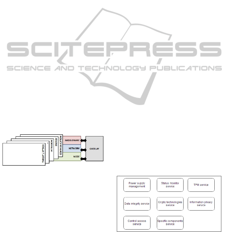
sortium, 2012). nSHIELD framework envisions a sys-
tem architecture (see Figure 1) that consists of four
functional layers: three horizontal ones - Node, Net-
work and Middleware, all comprehended by the sin-
gle vertical layer called Overlay. The SPD function-
alities are exercised at each of the horizontal layers,
with the Overlay layer having a logical operational
control, i.e. being in charge of decision-making with
respect to which of the SPD functionalities are to be
activated/deactivated at a particular time instance in
order to reach a desired SPD level. Desired SPD level
can either be imposed manually by the operator or, in
case of intelligent automated systems, by the corre-
sponding cognitive entity.
Figure 1: nSHIELD system architecture.
The Node layer encompasses physical elements
that constitute the nSHIELD network, and can be di-
vided into three basic types of embedded devices, dis-
tinguishable mainly by their computational capabili-
ties and power restrictions:
• Nano nodes – constrained battery-powered nodes
with low computational capabilities and low re-
configurability potentials. They typically require
a set of lightweight security protocols, and are
capable of running light operating system, i.e.
EasyOS, ContikiOS or Arduino. Nano nodes
can further be subdivided into nSHIELD-enabled
nano nodes and nSHIELD-compliant nano nodes,
where the first ones are capable of deploying one
or more of the SPD functionalities, whereas the
latter ones don’t have the SPD functionalities em-
bodied, but are able to communicate and inter-
operate with the nSHIELD-enabled nodes. Ex-
amples of currently available commercial embed-
ded platforms that correspond to the definition of
Nano nodes are e.g. Zolertia Z1 (Zolertia, 2013),
Arduino Uno (Arduino, 2013) and Memsic IRIS
(Memsic, 2013).
• Micro nodes – mid-class unconstrained nodes
with medium computational capabilities, embod-
ied with a single GPP and able to run Linux ker-
nels. They are typically DC-powered and have
the potential for deployment of a large number of
SPD functionalities. Examples of commercially
currently available embedded platforms that cor-
respond to the definition of Nano nodes are e.g.
Beaglebone (Beagleboard, 2013c), Beagleboard
(Beagleboard, 2013a) and Raspberry PI (Raspber-
ryPiFoundation, 2013).
• Power nodes – high-class unconstrained nodes
with advanced computational capabilities, typi-
cally embodied with multiple processing units and
able to run high-level operating systems such as
WinCE and QNX. Examples of commercially-
available platforms that can be considered as
power nodes are Beagleboard-xM (Beagleboard,
2013b) and ZedBoard (ZEDBoard, 2013). These
nodes may further be embodied with the widely
tunable RF front end, or connected to the full
Software Defined Radio, making them a ”SDR-
capable power node”.
The full set of the SPD functionalities devel-
oped for the Node layer is shown in Figure 2.
Which of the functionalities are being exercised at
a given time instance depends on the node class
(Nano/Micro/Power) and the SPD level imposed by
the Overlay.
Figure 2: SPD functionalities at the Node layer.
The Network layer is a heterogeneous layer in
charge of provisioning an SPD-enabled communica-
SPD-drivenSmartTransmissionLayerbasedonaSoftwareDefinedRadioTestBedArchitecture
221

tion between two or more nSHIELD nodes and/or
the external world. It is composed of a common
set of cooperating protocols, procedures, algorithms
and communication technologies, which are classified
into four innovative features:
• SPD-driven Smart Transmission Layer – feature
built specifically for the SDR-capable power
nodes (unconstrained devices with high reconfig-
urability potentials), whose goal is ensuring reli-
able and robust communication in harsh and criti-
cal conditions by utilizing on-the-fly reconfigura-
bility prospects of Software Defined Radio tech-
nology and - eventually - the learning prospects
that Cognitive Radio technology brings.
• Distributed Self-x Models – a set of distributed
self-management and self-coordination schemes
for unmanaged and hybrid managed/unmanaged
networks, whose goal is reducing the vulnerabil-
ity to attacks depleting communication resources
and node energy. This feature is not dependent
upon the node class, but rather upon the network
model and topology.
• Reputation-based Resource Management Tech-
nologies – when possible, keeping track of the be-
haviour of the network’s nodes can provide sig-
nificant improvements to the overall security, as it
can assist in singling out continuous anomalous,
malicious and unwanted behaviour. Hence, this
feature (Gerrigagoitia et al., 2012) will provide
efficient solutions based on trust level and repu-
tation tracking, allowing for secure routing pro-
tocols and functional intrusion detection systems
at the communication level. In centralized net-
works, Reputation-based RMTs will be deployed
at the central entity, thus being independent of the
classes of nodes that comprise the network. In ad-
dition to that, certain aspects of Reputation-based
RMTs are tailored and deployed to suit each of
the node types, allowing for the feature to ensure
SPD provisioning (to a certain level) in distributed
environments as well.
• Trusted and Dependable Connectivity – refers to
the set of SPD communication protocols deployed
at the network and link layer, whose focus is
put on lightweight adaptations of the well-known
Transport Layer Security (TLS) protocol, Data-
gram Transport Layer Security Protocol (DTLS)
and Internet Protocol SECurity (IPsec) (Rantos
et al., 2013) with its encoded version for IPv6
over Low power Wireless Personal Area Net-
works (6LoWPAN). In addition, this work task
deals with the access control applied specifically
to Smart Grid networks.
SPD functionalities developed for the Network layer
are outlined in Figure 3.
Figure 3: SPD functionalities at the Network layer.
The Middleware is a software layer installed in
the nSHIELD nodes, whose complexity depends on
the node class - lightweight middleware solutions are
deployed for the nano nodes, and high-complex solu-
tions for the power nodes. Middleware acts as ”glue”
for different SPD services offered by the nSHIELD
system, as - by means of dedicated protocols, con-
trol algorithms and interfaces - it allows for the ab-
straction, discovery, composability and control of all
of them. Middleware services and functionalities are
depicted in Figure 4.
Figure 4: SPD functionalities at the Middleware layer.
The Overlay is a logical vertical layer in charge of
deciding, in accordance with the control algorithms
and policies, which SPD functionalities should be ac-
tivated/deactivated at a given time instance, and to tai-
lor them in order to reach the nSHIELD objectives
(i.e. the desired SPD level). This layer is indeed a
software routine running over the nSHIELD Middle-
ware, which uses Middleware core services in order
to collect information and actuate its decision-making
process. nSHIELD Overlay offers five services, par-
tially overlapping with the services offered by Mid-
dleware. They are depicted in Figure 5.
Validation of the concepts developed within the
nSHIELD project will be demonstrated by the means
of four independent scenarios/demonstrators:
PECCS2014-InternationalConferenceonPervasiveandEmbeddedComputingandCommunicationSystems
222
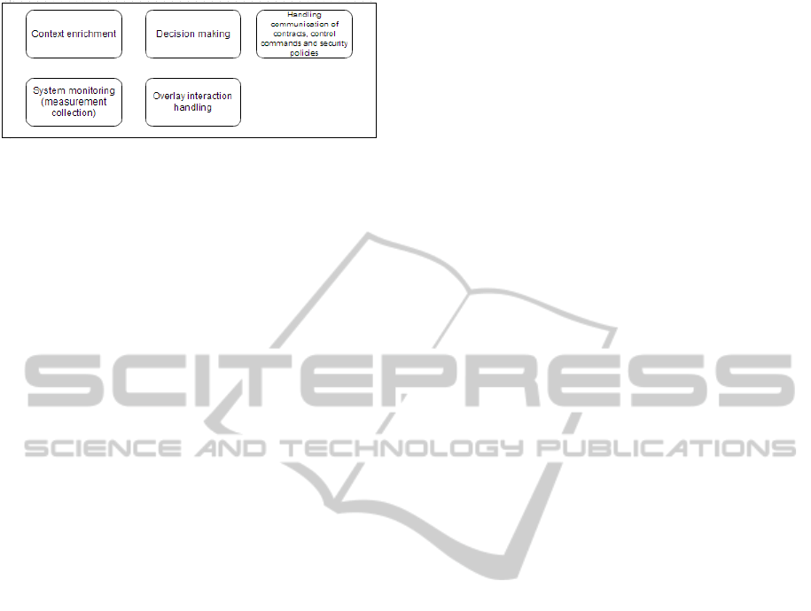
Figure 5: SPD functionalities at the Overlay layer.
• Urban railways protection
• Voice/facial recognition
• Dependable avionic systems
• Social mobility
For page limitation purposes, we are omitting a
more detailed outlook on the demonstrators, and the
project’s ideas and methodologies as a whole. These
may, however, be found at (nSHIELD Consortium,
2012), (Fiaschetti et al., 2012), (Esposito et al., 2013),
(Flammini et al., 2011). The focus is instead placed
on the implementational details of the SPD-driven
Smart Transmission Layer, and the corresponding test
bed architecture, discussed in more detail in the next
section.
4 TEST BED ARCHITECTURE
The proposed Smart Transmission Layer SDR/CR
test bed consists of a number (currently: 2) of Se-
cure Wideband Multi-role - Single-Channel Hand-
held Radios (SWAVE HHs), each interconnected with
the proprietarily developed multi-processor embed-
ded platform (Power node).
4.1 SWAVE HH Architecture Overview
SWAVE HH (SelexES, 2013) (from now on referred
to as HH) is a fully operational SDR radio terminal ca-
pable of hosting a multitude of wideband and narrow-
band waveforms. Maximum transmit power of HH
is 5W, with the harmonics suppression at the trans-
mit side over -50 dBc. Superheterodyne receiver has
specified image rejection better than -58 dBc. The
receiver is fully digital; in VHF, 12-bit 250 MHz ana-
log to digital (AD) converters perform the conversion
directly at RF, while in UHF, AD conversion is per-
formed at intermediate frequency (IF). No selective
filtering is applied before ADC. Broadband digitized
signal is then issued to the FPGA, where it under-
goes digital down conversion, matched filtering and
demodulation.
Being a military technology, several technical
characteristics of SWAVE HH, i.e. processor specifi-
cations and more in-depth operational details are non-
disclosable.
HH has an integrated commercial Global Position-
ing System (GPS) receiver, but also provides the in-
terface for the external GPS receiver. GPS data is
available in National Marine Electronics Association
(NMEA) format and may be outputted to the Ethernet
port.
Radio is powered by Li-ion rechargeable batter-
ies, however may also be externally powered through
a 12.6V direct current (DC) source. Relatively small
physical dimensions (80x220x50 mm), long battery
life (8 hours at the maximum transmission power for
a standard 8:1:1 duty cycle), and acceptable weight
(960g with battery) allow for portability and unteth-
ered mobile operation of the device.
Hypertach expansion at the bottom of HH pro-
vides several interfaces, namely: 10/100 Ethernet;
USB 2.0; RS-485 serial, DC power interface (max
12.7V), and PTT. The radio provides operability in
both Very High Frequency - VHF (30 - 88 MHz),
and Ultra High Frequency - UHF (225 - 512 MHz)
band. The software architecture of the radio is com-
pliant with the Software Communications Architec-
ture (SCA) 2.2.2 standard. Following that, HH pro-
vides support for both legacy and new waveform
types. Currently, two functional waveforms are in-
stalled on the radio: SelfNET Soldier Broadband
Waveform (SBW) and VHF/UHF Line Of Sight (VU-
LOS), as well as the waveform providing support
for the Internet Protocol (IP) communication in ac-
cordance with MIL-STD-188-220C specification (Li
et al., 1995). Currently installed waveforms will be
described and analyzed in more details in section 5.2.
4.2 Power Node Architecture Overview
and Connection to SWAVE HH
nSHIELD Power node is composed of a small form
factor System-on-Module (SOM) with high computa-
tional power - developed by Selex ES - and the corre-
sponding carrier board. It is based on an ARM Cor-
tex A8 processor running at 1Ghz, encompassed with
powerful programmable Xilinx Spartan 6 FPGA and
Texas Instruments TMS320C64+ DSP. It can be em-
bodied with up to 1 GB LPDDR RAM, has support
for microSD card up to 32 GB, and provides inter-
faces for different RF front ends. Support for IEEE
802.11 b/g/n and ANT protocol standards are prof-
fered. Furthermore, several other external interfaces
are provided, i.e. 16 bit VGA interface; Mic-in, line-
in and line-out audio interfaces; USB 2.0; Ethernet;
SPD-drivenSmartTransmissionLayerbasedonaSoftwareDefinedRadioTestBedArchitecture
223
and RS-232 serial. The node is DC-powered, and
has Windows CE and Linux distribution running on
it. System architecture of the Power node is shown in
Figure 6.
Connection to HH is achieved through Ethernet,
as well as serial port. Ethernet is used for the re-
mote control of the HH, using SNMP. For the serial
connection, due to different serial interfaces - RS-
232 and. RS-485, a RS-232-to-RS-485 converter is
needed. Serial connection is used for transferring the
spectrum snapshots from HH to Power node. More
details on remote control and spectrum sensing are
given in sections 5.1 and 5.4, respectively.
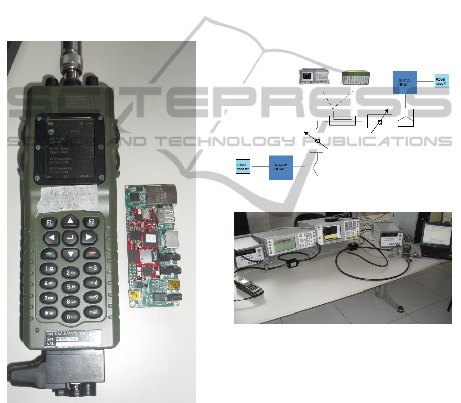
Figure 7: Implementations of SWAVE HH and the SOC
Power node.
4.3 Assembled Test Bed
Current test bed prototype is composed of two
SWAVE HHs, each interconnected with a Power
node. A coaxial RF bench was implemented for the
frequency range of interest. Because of the high out-
put power of the radios, two programmable attenua-
tors had to be included in the coaxial path, and were
programmed to their maximum attenuation value -
30 dB. Agilent 778D 100 MHz - 2GHz dual di-
rectional coupler with 20dB nominal coupling was
placed between the attenuators, allowing for sam-
pling and monitoring the signal of interest. Agilent
E4438C vector signal generator was connected to in-
cident port of the coupler, with the purpose of in-
jecting noise/interference signal to the network. Agi-
lent E4440A spectrum analyzer was connected to the
coupler’s reflected port, facilitating the possibility of
monitoring the RF activity. Simplified block diagram
of the test bed, and implementation are shown in Fig-
ures 8 and 9 respectively.
Figure 8: Test bed simplified diagram.
Figure 9: SPD-driven Smart Transmission Layer test bed
implementation.
5 CASE STUDIES
Smart Transmission Layer based on the described test
bed architecture is currently in its early implemen-
tation phase. However, several basic functionalities
have already reached demonstrable level. These will
be described in more details as follows.
5.1 Remote Control of the Radio
Using Simple Network Management Protocol v3
(SNMP v3), several parameters of the HH radio may
PECCS2014-InternationalConferenceonPervasiveandEmbeddedComputingandCommunicationSystems
224
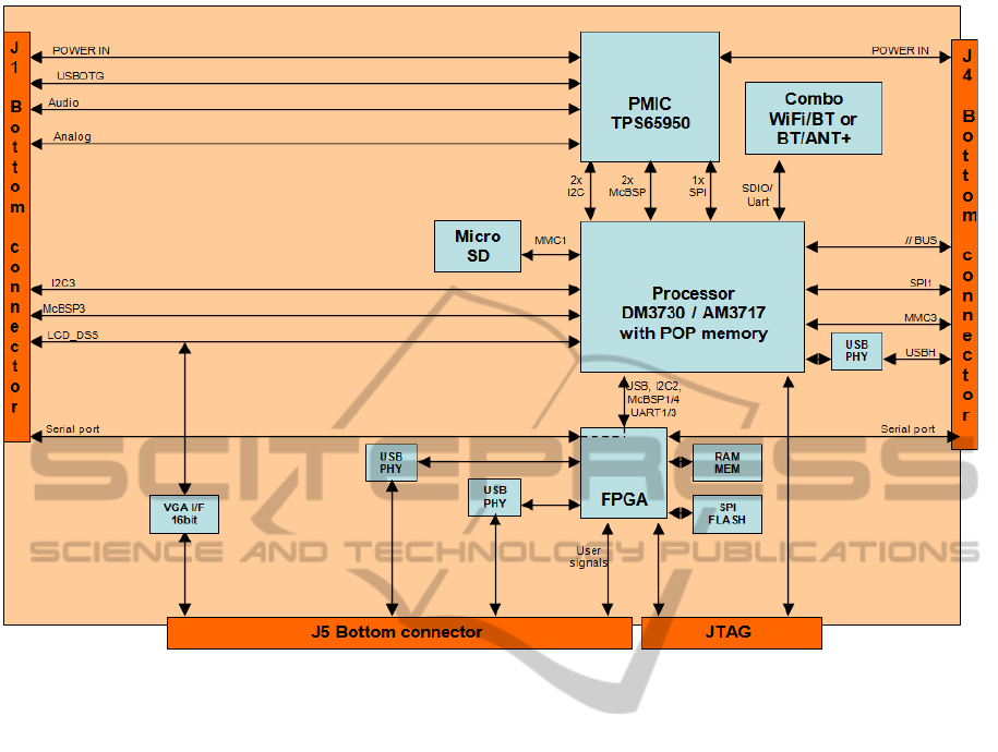
Figure 6: nSHIELD Power node - system architecture.
be externally controlled. For achieving this, SNMP
manager has to be installed and running on the Power
node. The host (Power node) and the agents (HHs in
the network) are connected through an Ethernet hub,
and need to be on the same domain.
By utilizing three basic SNMP commands: GET,
SET and TRAP, it is possible to: read the current
value of the parameter, set a new value, or issue a
message/warning if the current value satisfies a con-
dition, respectively.
The controllable parameters and their correspond-
ing features are stored in a Management Information
Base (MIB), which is loaded into the host’s SNMP
manager. MIB table contains all the definitions that
define properties of the controllable parameters, and
describes each object identifier (OID), which is origi-
nally a sequence of integers, with a string.
The list of the parameters that may be controlled
externally, with the corresponding input data types,
and the SNMP commands that may be invoked is
given in Table 1. Since the parameters are self-
explanatory, we are omitting a detailed description on
them. ManageEngine MibBrowser Free Tool (Man-
ageEngine, 2013) was used as the SNMP manager
running on the power node.
Accordingly, Table 2 provides list of the parame-
ters that may be TRAPped, with the short description
of the conditions under which TRAPping messages
are issued.
5.2 Waveform Analysis
As previously stated, there are currently two func-
tional wavevorms installed on SWAVE HHs: SBW
and VULOS. Having a wideband spectrum analyzer
allows for monitoring the waveforms and analyzing
their parameters.
SBW is a wideband multi-hop Mobile Ad-hoc
NETwork (MANET) waveform, supporting operation
in the 225 - 512 MHz part of the UHF band. The
waveform provides self-(re)configurability and self-
awareness of the network structure and topology, for
up to 50 nodes and up to 5 hops. Furthermore, possi-
bility of simultaneous streaming of voice and data ser-
vices is provided, with prioritization for voice stream-
ing (in case of exceeded bandwidth). Allocated chan-
nel bandwidth is adjustable - up to 5 MHz - with chan-
nel spacing of up to 2 MHz. SBW uses a fixed digital
modulation technique.
Self-awareness is exercised by monitoring the net-
work topology for changes every n seconds (monitor
interval is adjustable). Two Quality of Service (QoS)
SPD-drivenSmartTransmissionLayerbasedonaSoftwareDefinedRadioTestBedArchitecture
225
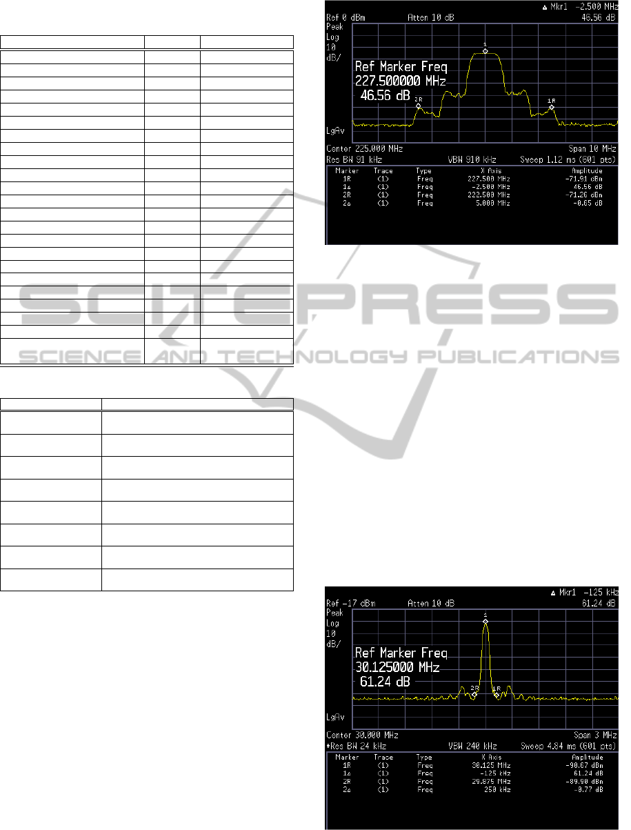
Table 1: HH’s Parameters that may be remotely controlled
via SNMP.
Parameter Type SNMP commands
File Transfer Activation string SET/GET
File Transfer Type string SET/GET
FTP User Name string SET/GET
FTP Password string SET/GET
FTP Address string SET/GET
Login Username string SET/GET
Login Password string SET/GET
Transmit Power integer SET/GET
Transmitter On/Off integer SET/GET
Currently Installed Waveform string seq GET
Waveform’s MIB Root string GET
Waveform Status [ON/OFF] integer SET/GET
Audio Message ID string SET/GET
Create New Waveform string SET/GET
Activate Preset string SET/GET
Activate Mission File string SET/GET
Audio Output Gain float SET/GET
Battery Charge Percentage integer GET
File Download Status integer GET
Trap Receiver’s IP Address string SET/GET
Zeroize All Crypto Keys integer SET/GET
Crypto Key Loaded integer GET
System End Boot [failed/
succeeded/ in progress] integer GET
Table 2: HH’s Parameters that may be TRAPped via SNMP.
Parameter Description
NET Radio OK The notification is triggered when the visibility
of the radio network is acquired
NET Radio FAIL The notification is triggered when the visibility
of the radio network is lost
Critical Alarm The notification is triggered when the HH
has sustained a critical operational error
End Boot The notification is triggered when successful
boot-up of the HH has been verified
End File Download The trap notifies end of the procedure of file
download, indicating whether it was sucessful
Low Power The notification is triggered when the battery
charge falls below a pre-defined limit
Create Waveform OK The notification is triggered when the
waveform is successfully created
Create Waveform FAIL The notification is triggered when the
waveform creation has failed
monitoring mechanisms are provided: Bit Error Rate
(BER) Test, and the statistics data for the transmit-
ting/receiving side. These mechanisms are provid-
ing means for analyzing and comparing the quality of
communication in regular and impaired channel con-
ditions. More in-depth analysis of these features is
presented in section 5.3.
Figure 10 shows envelope shape and properties of
the SBW waveform, for the maximum signal band-
width (5 MHz) and 1/10th of the maximum transmit
power (-3 dBW), in frequency domain.
VULOS is a narrowband single-hop waveform
designed for short-distance voice or data communi-
cation. It supports operation in both VHF (30-88
MHz) and UHF (225-512 MHz) frequency bands.
The waveform allows for choosing between two ana-
Figure 10: SBW waveform in the frequency domain - max
hold.
log modulation techniques: Amplitude Modulation
(AM) and Frequency Modulation (FM), which may
be configured on-the-fly, alongside with the modula-
tion index. Channel bandwidth is adjustable up to 25
kHz, with channel spacing also adjustable up to 25
kHz. Furthermore, the VULOS waveform is able to
utilize both digital and analog voice Coder-Decoders
(CODECs) installed on the radio.
Figure 11 shows envelope shape and properties of
FM-modulated VULOS waveform with the 25 kHz
bandwidth, transmitted at 1 dBW in VHF band (30
MHz).
Waveform analysis will have an important SPD
application - by creating a database of waveform
types that are occurring in the system, it will be pos-
sible to identify potentially malicious or misbehaving
users.
Figure 11: FM-modulated VULOS waveform in the fre-
quency domain - max hold.
PECCS2014-InternationalConferenceonPervasiveandEmbeddedComputingandCommunicationSystems
226
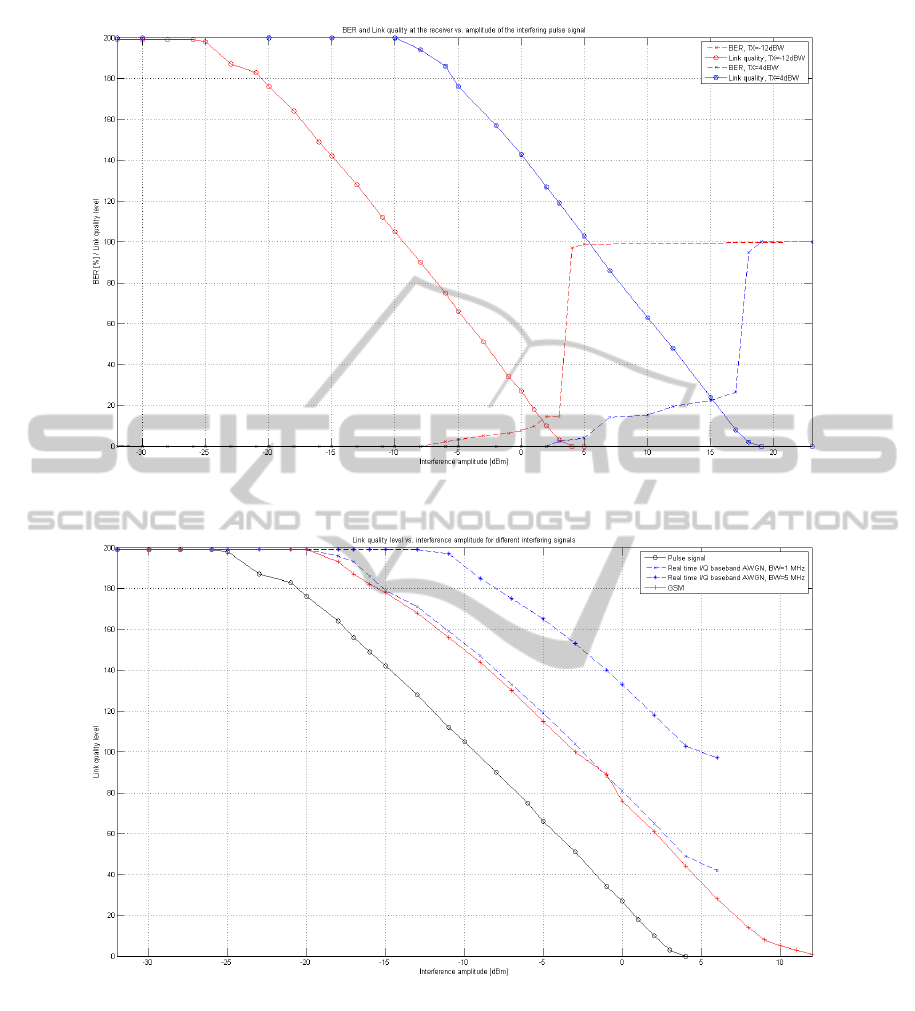
Figure 12: BER and Link quality level vs. interference amplitude of interfering pulse signal.
Figure 13: Link quality level vs. interference amplitude for different interfering signals.
5.3 Interference Detection
Various Denial of Service (DoS) attacks - and in par-
ticular jamming attacks - have for a long time been
posing - and continue to pose - significant security
threats to radio networks. Radiofrequency (RF) jam-
ming attacks refer to the illicit transmissions of RF
signals with the intention of disrupting the normal
communication on the targeted channels. RF jam-
ming is a known problem in modern wireless net-
works, and not an easy one to counter using tradi-
tional hardware-based equipment. Additionally, Soft-
ware Defined Radios and Cognitive Radios bring the
prospect for further improvement of the jamming ca-
pabilities of the malicious users, however also of-
fer the possibility of developing advanced protection-
and counter-mechanisms (Tague, 2010), (Morerio
et al., 2012).
One of the main focuses of the SPD-driven Smart
Transmission Layer is precisely providing safe and
SPD-drivenSmartTransmissionLayerbasedonaSoftwareDefinedRadioTestBedArchitecture
227

reliable communication in jamming-polluted environ-
ments. For that, a detailed study of various jamming
attack strategies and development of appropriate se-
curity solutions will be done.
The vector signal generator is presently used as
means for creating disturbances in the communica-
tion channel, emulating a simple RF jammer. A set of
measurements demonstrating how different types of
created interfering signals influence the performance
of the communication on the channel was done.
In the first set of measurements, the aim is to show
the correlation between Bit Error Rate (BER) and the
radio’s built-in Link Quality metric. Link quality is
HH’s built-in QoS feature, and is represented by an
integer in the range of [0-200]. The measurements
are done with HHs having their signal bandwidths set
to the maximum value (5 MHz), and repeated for two
transmitting powers: -12dBW and 4 dBW. Created in-
terfering signal is a pulse signal, created at the same
frequency as the frequency of the channel used for
communication between radios (225 MHz). Ampli-
tude of the created interfering signal varies. The re-
sults are presented in figure 12.
BER percentage is shown in the first half of the
Y-axis (0-100), whereas Link quality level stretches
throughout the whole Y-axis (0-200). The BER
curves are mutually similarly shaped, with the ex-
pected offset due to differing transmission powers of
the radio. The same goes for the link quality curve
shapes. As can be seen, occurrence of errors at the
receiving side (area where BER>0) corresponds to
Link quality levels in the range of [90-120]. As ex-
pected, 100% BER corresponds to the link quality of
0, meaning the communication has become impossi-
ble.
In the second set of measurements, different types
of interfering signals are created by the signal gener-
ator, namely: pulse signal as in the first measurement
set; Real Time I/Q Baseband Additive White Gaus-
sian Noise (AWGN) with the effective bandwidth of
5 MHz; Real Time I/Q Baseband AWGN with the
effective bandwidth of 1 MHz, and a GSM signal.
Once again, central frequency of all of the interfer-
ing sources is the same as the frequency of the chan-
nel that the radios use for communication (225 MHz).
The results are shown in figure 13.
As expected, pulse signal has the best interfering
capabilities, due to the fact that it has the most con-
centrated power, and - importantly - that it has been
created at the exact frequency as the main carrier fre-
quency of the transmitted signal. Even with small fre-
quency offsets, interfering impact of the pulse signal
would drop significantly. For the same reason, ad-
dition of AWGN results in higher link degradation
in cases of smaller allocated bandwidth, due to the
higher power density. The vector signal generator is
only able to produce an AWGN signal of amplitude
up to 20 dBm, hence the measurements for the higher
values were not done.
It should be noted that the results presented in this
subsection are for reference, instead of absolute pur-
poses - at this stage, the intention was not placed upon
emulating real-life interferers, but rather at perform-
ing the initial study of the interference detection func-
tionalities of the SWAVE HHs.
5.4 Energy Detection Spectrum Sensing
Obtaining information of the current spectrum occu-
pancy is paramount for the Cognitive Radios to be
able to opportunistically access spectrum, but may
also aid them in recognizing anomalous or malicious
activity by comparing the current state to those stored
in their databases. There are three established meth-
ods for CRs to acquire knowledge of the spectrum oc-
cupancy: spectrum sensing (Axell et al., 2012), ge-
olocation/database (Gurney et al., 2008), and beacon
transmission (Lei and Chin, 2008). HH has a capabil-
ity of performing energy detection spectrum sensing.
Every 20 seconds, 8192 samples from the ADC
are transmitted over the RS-485 port - this is a func-
tionality hard-coded in the HH’s FPGA. Each sample
is transmitted in two bytes: first byte containing the 6
most significant bits (MSBs), with 2 bits sign exten-
sion on the left. Second byte contains the 8 LSBs. In
total, 16384 characters are transmitted, making up for
the interpretation of a 16-bit word. Currently, there
is not a synchronization pattern - however the idle in-
terval between the two transmissions may be used to
e.g. perform analysis of the received data. Transmis-
sion of a full window takes approximately 2 minutes.
The signal at the HH’s FPGA input is a sample
of raw spectrum. Raw samples are stored in a RAM
buffer internal to the FPGA, and output through HH’s
fast serial port to the Power node, where they can be
processed.
Due to the high speed of the ADC (250 MHz), se-
rial port speed (38400 bit/s is supported in the asyn-
chronous mode) is not sufficient for the true real-
time transfer; in addition - processing capabilities of
the Power node would be completely devoted to the
processing of received signal, leaving no room for
higher level applications. Power consumption would
be heavily affected as well.
Adopted solution is to perform a quasi-real-time
acquisition, i.e. to collect a large snapshot of incom-
ing spectrum, i.e. tens of kilo-samples, and to transfer
the snapshot to the Power node. When the snapshot
PECCS2014-InternationalConferenceonPervasiveandEmbeddedComputingandCommunicationSystems
228

has been transferred, a new collection may start. This
is sufficient for proper analysis of the majority of RF
scenarios: in practice, only fast pulsed signals might
be completely missed.
Future hardware enhancements might make real-
time spectrum acquisition possible.
6 CONCLUSIONS AND FUTURE
WORK
The paper has introduced concept and basic premises
of the SPD-driven Smart Transmission Layer, and has
described design details of test bed architecture that
will be used for its development, experimentation and
validation. Several case studies were performed us-
ing the test bed, demonstrating its basic capabilities.
Each of these capabilities needs to be studied and de-
veloped in more detail. Following that, future work
using the test bed will cover multiple topics, described
as follows.
From the security perspective, the near-future
work will focus on tackling the problems of advanced
and intelligent DoS jamming attacks in CRNs. Us-
ing software packages such as 33503A BenchLink
Waveform Builder Pro in combination with the vec-
tor signal generator, it will be possible to model var-
ious interfering attack strategies, and the appropri-
ate counter-strategies. Because of a variety of pos-
sible attacks and potential security breaches that Soft-
ware Defined Radio and Cognitive Radio technology
bring, provisioning the ultimate security, privacy and
dependability for SDR and CR systems is a challeng-
ing task. Addressing each of the identifiable security
threats separately, though, makes for a good starting
point towards achieving it.
The test bed itself will be embodied with another
HH + power node, with the corresponding auxiliaries,
allowing for examining more complex scenarios and
creating different network topologies.
Opportunistic spectrum access is inarguably one
of the most exciting features of prospective Cogni-
tive Radio Systems. Building upon the HH’s possibil-
ity of acquiring the spectrum occupancy information
through energy detection, briefly presented in this pa-
per, we aim at developing algorithms for spectrum in-
telligence - as the prerequisite for OSA.
Theoretical foundations for the nSHIELD frame-
work were also described in the paper. How-
ever, common hardware and software interfaces of
SPD-driven Smart Transmission Layer to the upper
nSHIELD layers - Middleware and Overlay - still
need to be decided upon in the future. Also, layers’
interdependability will need to be looked into more
closely. Hence, for the time being, the nSHIELD
Middleware and Overlay layers are being treated as
”black boxes”.
ACKNOWLEDGEMENTS
This work was developed within the nSHIELD
project (http://www.newshield.eu) co-funded by
the ARTEMIS JOINT UNDERTAKING (Sub-
programme SP6) focusing on the research of SPD
(Security, Privacy, Dependability) in the context of
Embedded Systems.
The authors would like to thank Selex ES and Sis-
temi Intelligenti Integrati Tecnologie (SIIT) for pro-
viding the equipment for the test bed, and the labora-
tory premises for the test bed assembly. Particular ac-
knowledgment goes to Virgilio Esposto of Selex ES,
for providing expertise and technical assistance.
REFERENCES
Arduino (2013). Arduino uno datasheet. http://arduino.cc/
en/Main/arduinoBoardUno.
Axell, E., Leus, G., Larsson, E., and Poor, H. (2012). Spec-
trum sensing for cognitive radio : State-of-the-art and
recent advances. Signal Processing Magazine, IEEE,
29(3):101–116.
Beagleboard (2013a). Beagleboard system ref-
erence manual. http://beagleboard.org/static/
BBSRM latest.pdf.
Beagleboard (2013b). Beagleboard xm system ref-
erence manual. http://beagleboard.org/static/
BBxMSRM latest.pdf.
Beagleboard (2013c). Beaglebone system reference man-
ual. http:// beagleboard.org/ static/ beaglebone/ latest/
Docs/ Hardware/ BONE SRM.pdf.
Cabric, D., Tkachenko, A., and Brodersen, R. W. (2006).
Experimental study of spectrum sensing based on en-
ergy detection and network cooperation. In Proceed-
ings of the first international workshop on Technology
and policy for accessing spectrum, TAPAS ’06, New
York, NY, USA. ACM.
Dabcevic, K., Marcenaro, L., and Regazzoni, C. S. (2013).
Security in cognitive radio networks. In T. D. Lagkas,
P. Sarigiannidis, M. L. and Chatzimisios, P., editors,
Evolution of Cognitive Networks and Self-Adaptive
Communication Systems, pages 301–333. IGI Global.
Esposito, M., Fiaschetti, A., and Flammini, F. (2013). The
new shield architectural framework. ERCIM News,
2013(93).
Farrell, R., Sanchez, M., and Corley, G. (2009). Software-
defined radio demonstrators: An example and future
trends. Int. J. Digital Multimedia Broadcasting, 2009.
Fette, B. A. (2006). Cognitive radio technology. Newnes/
Elsevier.
SPD-drivenSmartTransmissionLayerbasedonaSoftwareDefinedRadioTestBedArchitecture
229

Fiaschetti, A., Suraci, V., and Delli Priscoli, F. (2012). The
shield framework: How to control security, privacy
and dependability in complex systems. In Complex-
ity in Engineering (COMPENG), 2012, pages 1–4.
Flammini, F., Bologna, S., and Vittorini, V., editors (2011).
Computer Safety, Reliability, and Security - 30th In-
ternational Conference, SAFECOMP 2011, Naples,
Italy, September 19-22, 2011. Proceedings, volume
6894 of Lecture Notes in Computer Science. Springer.
Fragkiadakis, A., Tragos, E., and Askoxylakis, I. (2013).
A survey on security threats and detection techniques
in cognitive radio networks. Communications Surveys
Tutorials, IEEE, 15(1):428–445.
Gerrigagoitia, K., Uribeetxeberria, R., Zurutuza, U., and
Arenaza, I. (2012). Reputation-based intrusion detec-
tion system for wireless sensor networks. In Complex-
ity in Engineering (COMPENG), 2012, pages 1–5.
Gurney, D., Buchwald, G., Ecklund, L., Kuffner, S., and
Grosspietsch, J. (2008). Geo-location database tech-
niques for incumbent protection in the tv white space.
In New Frontiers in Dynamic Spectrum Access Net-
works, 2008. DySPAN 2008. 3rd IEEE Symposium on,
pages 1–9.
Lei, Z. and Chin, F. (2008). A reliable and power efficient
beacon structure for cognitive radio systems. Broad-
casting, IEEE Transactions on, 54(2):182–187.
Li, H., Amer, P. D., and Chamberlain, S. C. (1995). Es-
telle specification of mil-std 188-220 datalink layer -
interoperability standard for digital message transfer
device subsystems. In Proceedings of MILCOM ’95.
ManageEngine (2013). Mibbrowser free tool faq. http://
www.manageengine.com/products/mibbrowser-free-
tool/faq.html.
Memsic (2013). Memsic iris datasheet. http://
www.memsic.com/ userfiles/ files/ Datasheets/ WSN/
IRIS Datasheet.pdf.
Minden, G., Evans, J., Searl, L., DePardo, D., Petty, V.,
Rajbanshi, R., Newman, T., Chen, Q., Weidling, F.,
Guffey, J., Datla, D., Barker, B., Peck, M., Cordill, B.,
Wyglinski, A., and Agah, A. (2007). Kuar: A flexi-
ble software-defined radio development platform. In
New Frontiers in Dynamic Spectrum Access Networks,
2007. DySPAN 2007. 2nd IEEE International Sympo-
sium on, pages 428–439.
Mitola, J. and Maguire, G. Q. Jr. (1999). Cognitive ra-
dio: making software radios more personal. Personal
Communications, IEEE, 6(4):13–18.
Morerio, P., Dabcevic, K., Marcenaro, L., and Regazzoni,
C. (2012). Distributed cognitive radio architecture
with automatic frequency switching. In Complexity
in Engineering (COMPENG), 2012, pages 1–4.
nSHIELD Consortium (2012). New shield. http://
www.newshield.eu/.
Rantos, K., Papanikolaou, A., and Manifavas, C. (2013).
Ipsec over ieee 802.15.4 for low power and lossy net-
works. In Proceedings of the 11th ACM Interna-
tional Symposium on Mobility Management and Wire-
less Access, MobiWac ’13, pages 59–64, New York,
NY, USA. ACM.
RaspberryPiFoundation (2013). Raspberry pi home page.
http://www.raspberrypi.org/.
SelexES (2013). Swave hh specifications. http://
www.selexelsag.com/internet/localization/IPC/media/
docs/SWave-Handheld-Radio-v1-2012Selex.pdf.
Tague, P. (2010). Improving anti-jamming capability and
increasing jamming impact with mobility control. In
Mobile Adhoc and Sensor Systems (MASS), 2010
IEEE 7th International Conference on, pages 501–
506.
Tkachenko, A., Cabric, D., and Brodersen, R. (2006). Cog-
nitive radio experiments using reconfigurable bee2. In
Signals, Systems and Computers, 2006. ACSSC ’06.
Fortieth Asilomar Conference on, pages 2041–2045.
ZEDBoard (2013). Zedboard quick start. http://
www.zedboard.org/sites/default/files/documentations/
GSC-AES-Z7EV-7Z020-G-v1f-press.pdf.
Zolertia (2013). Zolertia z1 revc datasheet.
http://zolertia.sourceforge.net/wiki/mages/e/e8/
Z1
RevC Datasheet.pdf.
PECCS2014-InternationalConferenceonPervasiveandEmbeddedComputingandCommunicationSystems
230
