
Video Stream Transmodality
Pierre-Olivier Rocher
1,2
, Christophe Gravier
1
, Julien Subercaze
1,2
and Marius Preda
2
1
Laboratoire T
´
el
´
ecom Claude Chappe, T
´
el
´
ecom Saint-Etienne, Universit
´
e Jean Monnet, F-42000 Saint-Etienne, France
2
D
´
epartement ARTEMIS/GRIN, T
´
el
´
ecom SudParis, 91000 Evry, France
Keywords:
Video Encoding, Vectorization, Modality.
Abstract:
Transmodality is the partitioning of an image into regions that are expected to present a better entropy using
different coding schemes, depending on their structural density, at constant bandwidth. In this paper we
present the transmodality of video stream. Our contribution is a transmoder module that includes various
different optimized video codecs and implements the concept of transmodality on a set of video streams. We
evaluate our proposal with different kinds of video (in content term), and our algorithm shows comprehensive
results by saving up to 8% of bandwidth for the same PSNR in comparison with the state-of-the-art video
encoding baselines.
1 INTRODUCTION
Video communication accords for one of the highest
development slope among various internet applica-
tions for the last few years. It is forecasted to be one
of the main bandwidth consumer with respect to fu-
ture applications. Different kinds of applications are
using video compression: live TV, online newspapers,
social networks. . . Over the last few years, new appli-
cations have emerged and one of the most important
one is probably the Cloud Gaming. All cloud gaming
applications like Gaikai
1
or OnLive
2
are based on
remote rendering. Such a system is generally based
on two parts. On the server side, the game is rendered
and the current picture is encoded using a state-of-the-
art video encoder like MPEG-4 AVC (alias H.264),
then streamed to the clients. Currently, for all previ-
ously described applications, the compression engine
handles each image as an atomic element, regardless
if the image contains more or less homogeneous re-
gions. Adaptive encoding schemes bring new fea-
tures, both in size and quality term, but the video is
still processed as a pixel set. Some regions of the pic-
ture will be encoded with different parameters, but us-
ing the same global encoding scheme. The intuition
behind this work is to go one step beyond by defin-
ing an adaptive region-based encoding algorithm us-
ing fundamentally different encoding schemes. The
encoding scheme should be chosen independently for
1
http://www.gaikai.com/
2
http://www.onlive.com/
each region, depending on its structure and hetero-
geneity. In this paper we propose several video cod-
ing systems to encode one video stream.
The remainder of this paper is organized as fol-
lows: Section 2 presents a review of background liter-
ature. Section 3 details the concept of transmodality.
Section 4 presents our video encoding system from a
global perspective to detailed components. Section 5
is dedicated to comparative testing and Section 6 con-
cludes the paper and draws perspectives.
2 RELATED WORK
This section investigates existing work in the broad
field of video encoding. While a complete state-of-
the-art on video coding is out of scope of this paper,
we aim at focusing on relevant results in this part. We
present two major encoding methods relevant to our
approach: matrix-based and the one based on graph-
ics primitives. We also present their applications to
image and video coding. The initiated reader may
skip this section.
2.1 Image
We can consider two ways to store and manipulate a
picture. The first one is a matrix-based representation,
while the second one is based on graphics primitives.
Nowadays, both solutions coexist but each represen-
tation brings specific advantages and disadvantages.
28
Rocher P., Gravier C., Subercaze J. and Preda M..
Video Stream Transmodality.
DOI: 10.5220/0004892000280037
In Proceedings of the 16th International Conference on Enterprise Information Systems (ICEIS-2014), pages 28-37
ISBN: 978-989-758-029-1
Copyright
c
2014 SCITEPRESS (Science and Technology Publications, Lda.)

The following paragraphs present respective benefits
and drawbacks.
The matrix-based method is widely used for stor-
ing and sharing pictures. Such image representa-
tion, also known as raster or bitmap, is based on the
pixel definition. Under this method, images are repre-
sented as 2D-matrices. This is a very convenient way
for storing and even compressing pictures and pixel-
based compression algorithms are proved to be quite
efficient. The most common encoders are BMP, PNG,
JPEG. Although, its major drawback is decrease qual-
ity while zooming into the parts of the picture. Even
if the picture is not compressed, the original pixel el-
ement will eventually outsize the corresponding pixel
in the screen space. At this point, the picture quality
will strongly suffer from this limitation.
The second method does not use pixel as the ba-
sic element but instead makes use of graphic primi-
tives. Each graphic primitive is a mathematical objet,
like a point, a line or a polygon, and is defined by
a formal definition. This representation then uses a
set of graphic primitives to build an image. However,
More complex objects like splines, Bezier curves or
even non uniform rational basis spline (NURBS) can
be used. Each graphic primitive is positioned in a
reference system and bears specific attributes like its
color, shape or thickness. Due to this approach of im-
age representation, picture is first rendered and then
displayed. i.e. every point in the reference system is
computed using graphics primitives. The result of this
computation is what is being displayed on the users
device. The main advantage of this representation in-
cludes, independence from the rendered image size,
its compacity and required data to reconstruct a vec-
torized picture cost the same price in size term.
When a picture or a video is live recorded, the
raster format is used. Meantime, vectorization is the
format of choice mainly for Computer-Aided Design
(CAD) softwares. Due the increase of heterogene-
ity of display devices in our daily lives (IPTV, smart-
phones, tablets. . . ) multimedia content is now often
included in web pages. Whatever the screen’s size,
display picture quality is maximal.
Building a raster representation of a vector picture
is a trivial task, but the reverse process is not obvious
(Sun et al., 2007). References on this topic can be
found (Lai et al., 2009), (Zhang et al., 2009), (Orzan
et al., 2008), but proposed solutions are quite basic
and are most often limited to black and white pictures
processing. Some approaches to handle color exist
but they cannot bear with photo realistic pictures (nat-
ural shots).
In proceeding sections, we distinguish codec types
based on pixel and vector. The first one is related to
a raster representation while the second one denotes
the vector representation.
2.2 Videos
This subsection presents state-of-the-art video en-
coders (based on the MPEG-4 AVC video coding
standard). Our main focus is on literature aiming to
use several encoders to process a single video, but
also on existing adaptive solutions. The first para-
graph is a reminder on how a modern video encoder
is working.
To compress a video, it is first splitted into a so
called Group Of Pictures (GOP), which is basically
made of three different types of pictures called I, P
and B. An I picture is a reference picture also known
as a key frame. P pictures are predicted using a past
referenced picture.
B pictures are bi-predicted, using both past and
future P pictures (depending on the standard defini-
tion). Main steps of such encoders are prediction,
transformation, quantization and entropy coding. In
the encoder scheme the main step responsible of data
compression is quantization. In order to control the
final bitrate, the user can tune the quantization factor,
called Qp in most common implementations. Vari-
ous strategies can be applied to control this parameter
throughout the encoding process, like constant Qp or
constant bitrate (therefore with a non-constant Qp). A
little Qp value will ensure a good video quality. Fur-
thermore usually, when Qp = 0 the compression is
lossless. Resulting entropy coded data, and necessary
decoding information like prediction mode, motion
vectors, quantization factor form the encoded video
stream.
The previous paragraph described the main steps
of a state-of-the-art video encoder. We now focus on
systems using more than one video encoder to com-
press a video.
In (Chaudhury et al., 2011), (Khandelia et al.,
2008) some macroblocks are encoded in a paramet-
ric manner, using an Auto Regressive (AR) process
[9]. Selection of these macroblocks is done using a
particular edge detection. Some moving textures can
be modeled as a spatio-temporal AR process, which is
in fact a tridimensional basis model version. In their
system, I pictures are H.264 encoded, while P pic-
tures are encoded using the proposed method. The
process is based on 16 × 16 macroblock size (be-
cause of H.264). Macroblocks are then categorized
into two sets: with or without edges, where mac-
roblocks without edges are encoded with the proposed
solution. The quality assessment was done using the
Mean Opinion Score (MOS) system because the re-
VideoStreamTransmodality
29

construction scheme is statistically built. No informa-
tion within the video like spatial resolution, frames
per second or even related enconding time are ex-
ploited.
In (Zhu et al., 2007) authors offer to simply delete
some macroblocks during the encoding process, in or-
der to rebuild them by synthesis methods at the decod-
ing stage. The method chosen to regenerate missing
parts is the spatio-temporal patch searching. The sys-
tem is running with an I-P-B picture scheme. Some
tests have been conducted with QCIF videos, at 30
FPS using different Qp. Experimental results show
a bitrate reduction of about 38.8% with a quite simi-
lar image quality (although no objective metrics were
used).
In (Tripathi et al., 2012) the encoding process
is based on both a traditional bloc coding and on a
model coding. For such appraoch, they use a long-
term temporal redundancy. Object detection related
part is based on region of interest (ROI) algorithms,
these ROIs are detected using principal component
analysis (PCA). ROI areas are then segmented us-
ing graph-cut algorithms (Felzenszwalb and Hutten-
locher, 2004). Finally a resultant area analysis is
done, aiming to regroup some areas for whole opti-
mization. A tracking algorithm is used for following
ROIs in futures images. Theses ROIs areas, defined
by a rectangle and an angle are finally coded using an
active appearance model, which is statistically based.
While the literature provides several encoding sys-
tems using more than one encoder, these solutions ap-
ply only to P pictures. Our system aims at working on
every picture of the video, and not only P pictures,
like in (Chaudhury et al., 2011), (Khandelia et al.,
2008).
Jointly to this research, work on adaptive video
coding is largely present. One can discern two ma-
jor trends: the first needs several versions of a same
video; the second is based on a single version, which
is adapted in realtime. The first solution is covered
by the Scalable Video Coding (SVC), but also by the
upcoming MPEG-DASH standard. Several recent ar-
ticles can be found about the second adaptive way.
In (Tizon et al., 2011a) real time adaptation is per-
formed on video encoder as according to the network
delay. Latency measurements are done before the
launch of the system, but also periodically during the
whole process. This latency evaluation makes possi-
ble the detection of network congestion and then the
ability to take necessary actions to adapt the stream.
In (Tizon et al., 2011a), they use a Cloud Gaming ap-
plication, with an aim to to guarantee fluidity and re-
sponsiveness of the system. The proposed solution is
to reduce the quantization parameter (among all mac-
roblocks) and the necessary bitrate. In (Tizon et al.,
2011b), the assumption between importants objects to
the user and their position in the depth map is done. In
other words, more the object is close to the user, more
it is important. To reduce the necessary bitrate with-
out loosing in quality, they refine the Qp parameter,
acting at macroblock level.
There is a common thread between all these so-
lutions: they always use a set of pixel to encode and
adapt the video coding. All presented solutions are
using a standard version of H.264, We will use an op-
timized one. Adaptive technologies are largely used,
but they are all the time confined to the pixel world.
We will use an other type of encoding system, which
is based on vectorization.
3 TRANSMODALITY
We introduce a new way of encoding a video stream
using so called modalities. A modality is a set of areas
to be compressed regarding a specific encoder. Each
modality refers to (a) specific(s) part(s) in a frame, re-
garding an encoder especially well suited for encod-
ing corresponding areas in a picture. According to our
experiments we conclude that using more than one
encoder will achieve a better compression rate than
using only one, while preserving the same quality in
terms of Peak Signal to Noise Ratio (PSNR). Con-
ventional encoding approaches consider a video as a
set of pixels and use a single encoding scheme for the
whole set. Our approach is based on the assumption
that a dynamic partitioning of the video frames and
the approximation of some regions with a parametric
representation will reduce the video bitrate. Splitting
a video stream into objects and encoding them sepa-
ratly is the basis of MPEG-4 part 2, but the way of
doing this work on a video stream is not covered by
this standard.
3.1 Transmodality Definition
We define the Tansmodality as the fact of using sev-
eral specific encoders to compress the same video file.
The aim is to use a well-suited encoder to each region
and using different modalities for video encoding. In
other words, a modality is defined as being the com-
pression of an area set by an encoder.
We define a class as a set of areas, each class be-
ing encoded using one specific encoder. Using one or
more modalities is not known by advance but it be-
longs to the processed video itself. The decision to
use 1, 2 or n modalities is taken in real time during
multimodal encoding, which means that shapes and
ICEIS2014-16thInternationalConferenceonEnterpriseInformationSystems
30

area size are potentially different for each frame. For
instance, Figure 1 is made of five areas z
1
to z
5
which
are grouped into three classes m
1
to m
3
. An area is
a contiguous set of pixels, contiguity of two pixels is
defined using the Kronecker operator (V4 neighbor-
hood).
Figure 1: Areas and modalities in a sample picture.
Figure 2: Input picture.
3.2 Real Example
The whole splitting process is detailled step by step
in upcoming parts. As a basic example, Figure 2
presents a sample picture extracted from the ”Home”
movie
3
. If we choose picture details (large amount
of edges and colours) as a main criteria, then we can
denote two kinds of modalities in this picture: a quite
uniform, smooth one (i.e. the sky part), and another
one which contains more details (the skyscrapper it-
self). Figure 3 outputs a possible splitting result. The
reader can notice the rectangle at the bottom-left of
the tower due to a macroblocking effect. This effect
is discussed in Section 5.2.
The idea is to use several (two in this case) encoders to
process a single video and to demonstrate that the cor-
responding multimodal video is smaller in size, while
3
http://home-2009.com/fr/
Figure 3: Level of detail based sample splitting.
maintaining a good visual quality with minimal pro-
cessing time. This approach raises several issues, in-
cluding the choice of encoders and precision of the
process to separate modalities or the way the output
video stream will be written.
In the following section we focus on the trans-
moder whose role is to process the video compression
with multi-modalities.
3.3 Transmoder vs. Transcoder
A transcoder is a software or hardware element which
aims to modify the way how a video file or stream is
compressed. It first decodes a video file or stream, and
encodes it again using new parameters. This enables
the application to modify the way this video will be
transformed including three majors trends: the output
video size (spatial resolution), the frame rate (tempo-
ral resolution) and the quality (resolution in PSNR).
In this work, we introduce a new adjustable parameter
called modality. Doing so, we define a new applica-
tion called transmoder, which is a transcoder with an
ability of using modalities, as described in previous
sections. Our Transmoder as compared to transcoder
uses an additional parameter that increase the output
range of possible bitrates and thus make it possible to
distribute the video to a larger number of people. A
transmoder is also able to conduct simple transcod-
ing operations, so with regard to our definition, the
transcoder is a particular case of the transmoder.
In this work, we focus on implementing a trans-
moder that can handle two modalities, the pixel and
the vector ones. What follows therefore presents our
bimodal transmoder approach. In order to simplifiy,
following parts of this article will rely on a trans-
moder working on two modalities. The multimodal
process is then limited to a bimodal approach.
VideoStreamTransmodality
31
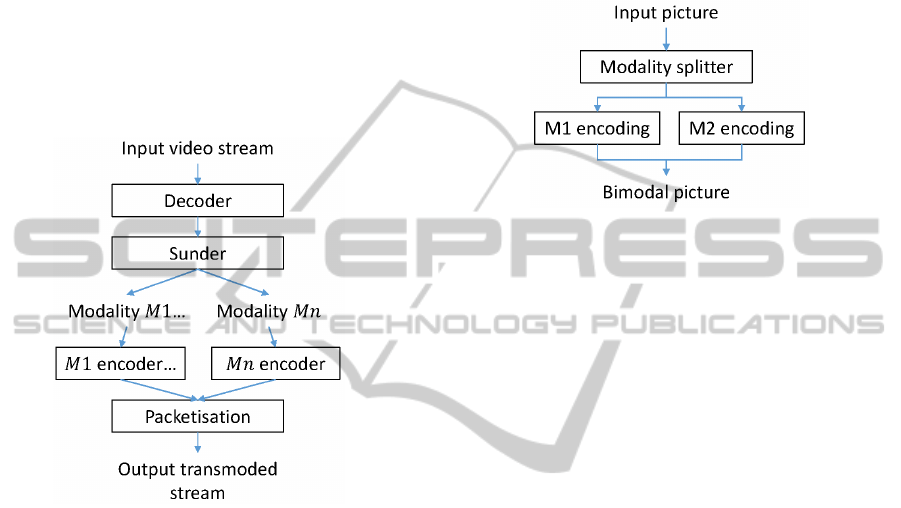
4 TRANSMODER PROCESS
Our transmoder is built on three separated parts: a
decoder, an encoder and a sunder. The whole archi-
tecture is presented in Figure 4. The decoder decodes
frames from a video file or stream. The sunder part
is in charge of the partitioning of each frame into n
modalities. As depicted in Figure 4, the sunder out-
put is a combination of n modalities denoted M1 to
Mn. Finally, the encoder uses the processed results
of sunder as its input and encodes the whole video in
a transmoded stream. The remaining systems blocks
are explained in the following sections.
Figure 4: Synoptical scheme of the transmoding process.
4.1 Decoding
Like every transcoder, our transmoder has a decoding
step. Decoding stage can be used or not either input
data is in a compressed form or not. If the user wants
to process a video file or stream, the decoding process
provides a raw picture to the sunder using an appro-
priate decoder. An other solution is to catch a raw
picture from a video game engine buffer for example
and directly input it in the sunder.
4.2 The Sunder
The aim of Sunder is to take the decision of splitting
(or not) the frame in several modalities. All the re-
quired step for such functionality as depicted in Fig-
ure 5 are explained later. But at this point we con-
sider that the input of this whole process is an un-
compressed picture, typically in an Red Green Blue
(RGB) raw format. Some image processing treat-
ments is first applied, then the picture is splitted into
modalities (4.2.1). Once both modalities are splitted,
respective encoding is conducted and some optimiza-
tions are applied on the pixel encoding part (4.2.2).
The ouput of this process is a so-called bimodal pic-
ture. While all necessary informations are available,
the video stream can be recorded. This is done by us-
ing packets, which are usually containing one frame.
Packetisation process is described in (4.3.3).
Figure 5: Synoptical scheme of the splitting process.
4.2.1 Modality Splitting
Modality splitting involves with splitting operation by
utilizing well known image processing filters. Previ-
ously, we explained our choice to split a picture into
two modalities. To operate efficiently, an image pro-
cessing filter appears to be the best choice. Our ap-
proach splits an image, based on the level of details
which can be performed using an edge detector filter.
There are various filters available for such require-
ments including Canny, Laplace an Sobel. For scali-
bility reasons, we require an algorithm that exhibits a
good trade-off between performance an computation
time. Under these conditions, (Heath et al., 1996) and
more recenlty (Maini Raman, 2009) concludes that
the Canny filter is the filter of choice. Furthermore,
this choice of filter is affirmed by (Zhang et al., 2009)
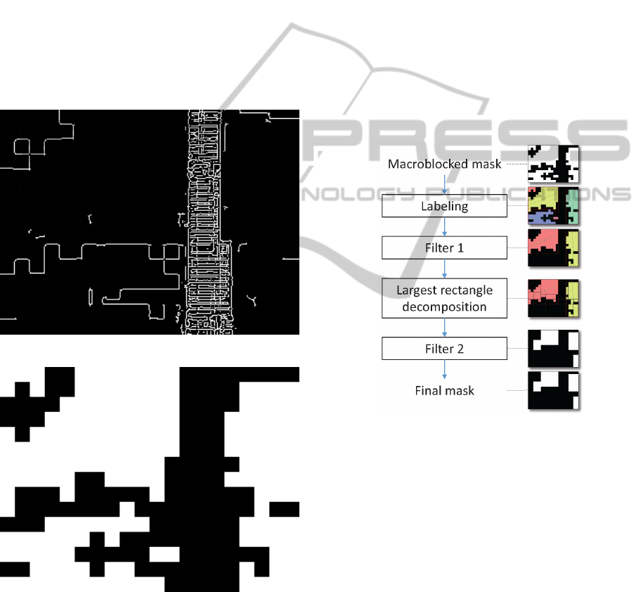
in which the authors processed videos. As an exem-
ple, lets take the picture presented in Figure 2 as an
input picture. After the edge detector process, we
obtain a binary picture as displayed in Figure 6. As
the reader can see, details in the picture are spotted
in white, and more uniform areas are in black. Some
morphological operations are now necessary to clean
this mask (remove single points, close holes. . . ).
At this point, we need to make a choice regarding
modality encoding. We choose to use one encoder
from the pixel world and another one from the vector
one. Chosen pixel encoder is the well-known MPEG-
4 AVC, the state-of-the-art reference. As literature
does not provide any efficient library for a raster to
vector convertion, thus we employ our own vectoriza-
tion module. It is designed to suit our specific needs
and is further described in 4.3.1. As we previously
said, in the binary mask black parts represents a high
ICEIS2014-16thInternationalConferenceonEnterpriseInformationSystems
32
amount of details while white parts depicts more uni-
form areas. Based on the characteristics of selected
encoders, Black parts may be pixel coded whereas
white parts may be vector coded. At this point, white
areas are candidates to be vector coded, but further
analysis (as described in 4.2.2) may downgrade them
in the pixel world to ensure a good compacity in the
output video stream. Because we choose to compress
a modality using a MPEG-4 AVC encoder, the binary
mask needs to be adapted since this kind of encoder
is based on a macroblock definition (a 16 × 16 pix-
els size). This is simply done in checking each pic-
ture macroblocks: if all pixels are black, then the
macroblock is black otherwise it is white. The cor-
responding new macroblock mask is depicted in Fig-
ure 7.
Figure 6: Canny filtered input picture representation.
Figure 7: Macroblocked representation of vector areas (in
white).
4.2.2 Analysis
This concludes as the most important step of trans-
moding. All decisions made here are based on param-
eters set by the user at startup time. Currently a mac-
roblock mask is present, the aim is now to process this
mask and take appropriate decisions. Important steps
of this analysis are presented in Figure 8.
Labeling: The first operation involves a V4 neigh-
bourhood labelling of white areas. This will ensure
that each vector area is separated from the others, and
provides an internal data structure easy to manipulate.
First Filter: Filter 1 as described in Figure 8 is re-
sponsible of the deletion of some area based on sur-
face size criteria as according to the threshold set by
the user. Consequently, some little areas which were
planned to be vector encoded is in place pixel en-
coded, because in this case a pixel encoder offers bet-
ter results. As an exemple, Figure 8 shows a possible
output result.
Figure 8: Logic analysis process in the sunder.
Largest Rectangle Decomposition: According to
Figure 8, we can now consider two areas. These ar-
eas can have any shape, including holes. To make the
decoding stage possible, we will need to know two
things: where are the vector areas and what are their
respective definitions. We need now to consider how
to store efficiently the binary mask. We can consider
a lot of different solutions but in all cases, we need
to keep a very good compacity. In order to fulfill this
need, we choose to decompose any vector area into
a set of largest rectangles. This kind of operation is
known as a rectangle decomposition of binary ma-
trix, henceforth DBMR problem. More information
on this subject can be found in (Ferrari et al., 1984).
Most of the time, taking into account the first two or
three biggest rectangles is enough to keep a good ap-
proximation of the intial shape.
VideoStreamTransmodality
33

Second Filter: Our second filter aims at deleting
little areas (user set thresold) that are moved in the
pixel modality. At the end of this analysis, only
important large rectangle areas are candidate for a
parametrized representation. This process is detailed
in Section 4.3.1.
This is the last step of sunder process. A binary
mask specifies if each area has to be compressed us-
ing the first or the second modality. Thus encoding
operations, related optimizations, and stream genera-
tion can be conducted.
4.3 Stream Encoding
The modality splitting step is now finished. All pixel
and vector areas are known and respective encoding
operations can be conducted. The first paragraph de-
scribes our vectorization process while the second one
is devoted to optimizations. Bimodal video stream is
then packetized and dumped in an output video file.
4.3.1 Vectorization
As described earlier, vectorization is not a trivial task,
especially when the user wants to process a natural
picture and expect good quality results. The main
problem of such encoding scheme includes complex-
ity of such a project, necessary time to process pic-
tures and output obtained sizes. All these parameters
are intimately related to the picture content. The de-
sirable objectives at this point is the implementation
of specific software that meets our need along with a
fast processing and a good quality (in term of PSNR).
Because as the previous operations provides only a
specific texture type and in order to achieve a uniform
one, we can utilize a simple vectorization approach.
As a first implementation we choose to simply use
a polynomial based approach, inspired by what has
been done in (Zhang et al., 2009). In order to vector-
ize an area, a 3D polynomial mean square based re-
gression is computed using a matrix approach. Each
polynomial expression is based on a static template of
the form: Z = a + bx + cy + dx
2
+ exy + f y
2
. Where
corresponding correlation coefficients are computed
for each area. This determines the quality of the vec-
torization per area. If the result is too poor in qual-
ity, the corresponding area will fallback in the pixel
mode.
4.3.2 Encoding Optimizations
Encoding a single video using a per area optimized
compression is not such a tedious task. The most dif-
ficult part is to use them correctly while avoiding re-
dundancy in the data stream and trying to limit the
impact on the encoding time. However, the only fact
of adding some new lines of code will inevitably in-
crease the necessary computing power.
Starting from this fact, we tried to minimize the
impact of the sunder in optimizing the way encoder
works. Both vector and pixel parts have been opti-
mized. After all areas are vectorized, a process checks
if some of them can be modeled using a same poly-
nomial definition. Special treatment is reserved for
writing vector data: for example, the number of digits
is limited and all the data is compressed. The sunder
process gives us some useful informations, which can
be directly sent to the encoder. We can denote two
optimizations: the first one (O1) directly indicates to
the encoder macroblock to skip, and the second (O2)
manipulates the Qp parameter. Each of these two op-
timization is macroblock based. The aim of O1 is to
directly provide a list of macroblock to encoder that
have to be skipped. Thus the analysis cost is reduced
(minimize the encoding time) and the stream is more
compact, regardless the chosen encoding preset. This
optimization is only applied on P frames. O2 opti-
mization is related to I and P frames. Per macroblock
Qp is modified to force the encoder to skip some mac-
roblocks (thus which are not used by the pixel modal-
ity). These two optimizations can be used separately
but also at the same time. They do not impact the
quality of the output stream.
4.3.3 Packetisation
For being able to add our vectorization data part, we
modify the way packetisation is done. Each vector
data is just positionned after the picture data, hence a
frame is a combination of pixel and vector data. Fig-
ure 9 presents a schematic representation of an H.264
stream on the left, and our modified one on the right.
As the splitting is done live in an automatic manner,
some packets may have only a pixel part, some oth-
ers only a vector part. This stream is written in such
a way that any compliant MPEG-4 AVC decoder will
be able to read it, however only the pixel modality will
be correctly displayed on the screen. In order to ren-
der and display the whole transmoded video stream,
i.e. both pixel and vector modalities, a suitable de-
coder is necessary.
Figure 9: Usual H264 bitstream at left, our customized at
right.
ICEIS2014-16thInternationalConferenceonEnterpriseInformationSystems
34

5 PERFORMANCE EVALUATION
We evaluate our solution using videos from the real
life. For such requirement, we download four dif-
ferent kinds of video from Youtube. We choose a
documentary
4
, a music video clip
5
, a basketball
movie
6
and a video game screen record
7
. Con-
tent of such videos is made of slow and fast scenes,
with any kind of areas: details, smooth parts. . . We
see our transmoder as a standalone application. As
a lot of parameters can be tuned and will inevitably
lead to differents results, we choose to use static pa-
rameters for testing. Both modalities coding param-
eters are fixed to make comparisons possible. Fur-
thermore the pixel video encoding strategy uses a
constant quantization parameter, which is set by de-
fault to Qp = 20. All testing movies have been re-
sized to a 480p resolution, frame number varies from
300 to 500 pictures. Optimzations presented in 4.3.2
are used. Our transmoder implementation outputs
XML files with all necessary informations, like frame
sizes, made decisions. . . Results between a classical
approach (transcoder) and our approach are then anal-
ysed.
5.1 Implementation
Video encoding is a quite heavy task even on most re-
cent computers. The choice of a native programming
language is then obvious. Because of code source
portability but also external available libraries, the
preferred choice for our implementation is C/C++. In
order to accelerate the developping time and reduce
the source code size to maintain, some well known
multimedia libraries were used, such as FFmpeg and
libx264 for decoding, encoding and manipulate the
different kind of codec and containers. Image pro-
cessing related operations are done by OpenCV, and
our basic vectorization software uses the GNU Scien-
tific library (GSL). The whole program is available
as a standalone executable capable of transmoding
any kind of videos, or as a library for direct split-
ting and encoding. Obviously the transmoder is also
capable of simple transcoding operations. Although
our model is designed for any number of modalities,
our current implementation is limited to two: a pixel
modality and a vector one.
4
http://www.youtube.com/watch?v=jqxENMKaeCU,
our shot start at 00:35:40 s
5
http://www.youtube.com/watch?v=AgFeZr5ptV8
&list=TLQurwwErDm7o
6
http://www.youtube.com/watch?v=7lvvoqEMHn4
&list=TLnMx7QuIzwoM
7
http://www.youtube.com/watch?v=NC39Ww9ZLgs
Table 1: Obtained sizes in bytes after transcoding (TC) and
transmoding (TM).
Video name TC size TM size % diff
Documentary 32774899 30796069 6.04
Music clip 2766735 2736886 1.08
Basketball 4465946 4481855 −0.35
Game screen rec. 3105475 2838761 8.6
All videos (Original, transcoded and transmoded
versions) from the tests carried out in the results sec-
tion are available
8
. Furthermore, necessary binary
files are also available, thereby experiments can be
reproduced by everyone.
5.2 Results
For our first experiment, we choose to compare the
transcoded and transmoded size according the origi-
nal file size. Both filters 1 and 2 were set to 1, which
means only one rectangle area is candidate for vec-
torization. Table 1 contains the result for all tested
videos.
We can see that our transmoder provides better results
in some cases, like with the documentary 6.04% bet-
ter or with the game record 8.6% better. In some
other cases, improvement is not significant (music
clip video, 1.08% increase in efficiency), for some
videos it may lead to a larger size. These observations
can be explained as our model is searching for smooth
areas in order to provide a more compact representa-
tion. Ability of finding such areas is directly related
to the video content, but also according video quality.
If the video quality is poor, the macroblocking effect
will provoke an over segmentation, resulting in less
interesting results. Using a multiscale edge detector
could solve this issue and will be investigated in fur-
ther research.
5.3 Quality Assessement
Quality assessment is not a trivial job and many well
known metrics including PSNR or MSSIM are used
to complete surveys. Our early tests use a PSNR met-
ric for quality assessment, with some particularities.
Indeed, we choose to compute a per modality and a
per frame PSNR value, aiming to preserve the maxi-
mum amount of information for later analysis.
Results on the quality assessement are presented
in Table 2. We denote three different tests. The
original video (O in the table) compared to the
transcoded version (TC) and original video compared
to the transmoded version (TM). Three times out of
8
http://datasets-satin.telecom-st-etienne.fr/porocher/
videos/2013/
VideoStreamTransmodality
35

Table 2: Quality assessement, using PSNR.
Video name O vs. TC O vs. TM TC vs. TM
Documentary 33.3664 33.7969 32.5094
Music clip 40.0416 37.1115 36.2243
Basketball 34.0789 35.9083 32.5832
Game screen rec. 42.0799 43.0613 43.4582
four, our transmoder gives better result compared to
the transcoded version of the original video (Docu-
mentary, Basketball and Game screen record). For
the documentary video, the PSNR increases, which
means that the video quality is better, while necessary
bitrate was reduced of about 6.04%. For the game
screen record: our transmoder saves 8.6% in bitrate
while increasing the PSNR from 42.0799 to 43.0613.
As a short conclusion, we can say that our trans-
moder can provide better results both in bitrate and
PSNR terms for most of the test videos.
5.4 Real Time Processing
Our first tests, presented in Table 3 reveal that real
time processing is possible with videos assuming
quite little spatial resolutions (240p). Using this spa-
tial resolution, a 29 framerate is possible for the mu-
sic clip. This framerate isn’t reachable for all tested
videos, as an example the documentary framerate is
only about 7 pictures per second. In order to over-
come this limitation, we first optimize the whole
architecture of the software, especially by adding
threading support in appropriate source code parts.
Another way of increasing performance, especially
in the image processing world is to use the GPU.
This aspect has been brought to our program using
OpenCV GPU related functions.
Table 3: Transmoding time (second) vs. spatial resolution.
Video name 240p 480p 720p
Documentary 65.52 142.28 295.73
Music clip 14.50 54.27 111.84
Basketball 56.11 128.45 281.19
Game screen record 18.03 113.08 261.17
6 CONCLUSION AND FUTURE
WORKS
In this paper, we presented a new kind of video en-
coding system called transmoder. The video stream
is splitted into regions that are encoded using sev-
eral modalities depending on the regions character-
istics. We propose an overall system architecture for
transmoding by employing two modalities, pixel and
vector encoding. We first split each frame into re-
gion using an edge detector and then determine the
more relevant encoder for each region. Where the
resulted output of biomodal video stream is a com-
bination of vector and pixel frames. We tested our
approach against several real life videos and perfor-
mance analysis shows that our approach significantly
outperforms state-of-the-art encoder for a large ma-
jority of testbed videos. These tests present a reduc-
tion of the necessary bitrate up to 8%. Future research
will allow us to optimize even more our system, us-
ing for example GPU optimized algorithms. In the
frame of our research on cloud gaming systems, we
aim to integrate this multimodal coding scheme in the
realtime rendering chain. We therefore adapt our ap-
proach for distributed processing in a cloud architec-
ture.
REFERENCES
Chaudhury, S., Mathur, M., Khandelia, A., Tripathi, S.,
Lall, B., Roy, S. D., and Gorecha, S. (2011). Sys-
tem and method for object based parametric video
coding. U.S. Classification: 375/240.16; 375/240.25;
375/E07.027; 375/E07.076.
Felzenszwalb, P. F. and Huttenlocher, D. P. (2004). Effi-
cient graph-based image segmentation. International
Journal of Computer Vision, 59(2):167–181.
Ferrari, L., Sankar, P., and Sklansky, J. (1984). Minimal
rectangular partitions of digitized blobs. Computer Vi-
sion, Graphics, and Image Processing, 28(1):58–71.
Heath, M., Sarkar, S., Sanocki, T., and Bowyer, K. (1996).
Comparison of edge detectors: a methodology and ini-
tial study. In Proceedings CVPR ’96, 1996 IEEE Com-
puter Society Conference on Computer Vision and
Pattern Recognition, 1996, pages 143–148.
Khandelia, A., Gorecha, S., Lall, B., Chaudhury, S., and
Mathur, M. (2008). Parametric video compression
scheme using AR based texture synthesis. In Sixth
Indian Conference on Computer Vision, Graphics Im-
age Processing, 2008. ICVGIP ’08, pages 219 –225.
Lai, Y.-K., Hu, S.-M., and Martin, R. R. (2009). Auto-
matic and topology-preserving gradient mesh gener-
ation for image vectorization. ACM Trans. Graph.,
28(3):85:185:8.
Maini Raman, D. H. A. (2009). Study and comparison
of various image edge detection techniques. Interna-
tional Journal of Image Processing.
Orzan, A., Bousseau, A., Winnemller, H., Barla, P., Thollot,
J., and Salesin, D. (2008). Diffusion curves: a vec-
tor representation for smooth-shaded images. ACM
Trans. Graph., 27(3):92:192:8.
Sun, J., Liang, L., Wen, F., and Shum, H.-Y. (2007). Im-
age vectorization using optimized gradient meshes. In
ACM SIGGRAPH 2007 papers, SIGGRAPH ’07, New
York, NY, USA. ACM.
ICEIS2014-16thInternationalConferenceonEnterpriseInformationSystems
36

Tizon, N., Moreno, C., Cernea, M., and Preda, M. (2011a).
MPEG-4-based adaptive remote rendering for video
games. In Proceedings of the 16th International Con-
ference on 3D Web Technology, Web3D ’11, pages
45–50, New York, NY, USA. ACM.
Tizon, N., Moreno, C., and Preda, M. (2011b). ROI
based video streaming for 3D remote rendering. In
2011 IEEE 13th International Workshop on Multime-
dia Signal Processing (MMSP), pages 1–6.
Tripathi, S., Mathur, M., Dutta Roy, S., and Chaudhury,
S. (2012). Region-of interest based parametric video
compression scheme. Communicated to the IEEE
Transactions on Circuits and Systems for Video Tech-
nology.
Zhang, S.-H., Chen, T., Zhang, Y.-F., Hu, S.-m., and Mar-
tin, R. (2009). Vectorizing cartoon animations. IEEE
Transactions on Visualization and Computer Graph-
ics, 15(4):618 –629.
Zhu, C., Sun, X., Wu, F., and Li, H. (2007). Video cod-
ing with spatio-temporal texture synthesis. In ICME,
pages 112–115.
VideoStreamTransmodality
37
