
A Framework for Concurrent Design of Metamodels and Diagrams
Towards an Agile Method for the Synthesis of
Domain Specific Graphical Modeling Languages
François Pfister
1
, Marianne Huchard
2
and Clémentine Nebut
2
1
LGI2P, Ecole des Mines d’Alès, site de Nîmes, Parc Scientifique G. Besse, 30000 Nîmes, France
2
LIRMM, CNRS, Université Montpellier 2, 161 rue Ada, 34095 Montpellier Cedex 5, France
Keywords:
Model Driven Architectures and Engineering, Modeling Formalisms and Notations, Domain Specific
Languages, Graphical Syntax, Concrete Syntax.
Abstract:
DSML (Domain Specific Modeling Languages) are an alternative to general purpose modeling languages
(e.g. UML or SysML) for describing models with concepts and relations specific to a domain. DSML design
is often based on Ecore metamodels, which follow the class-relation paradigm and also require defining a
concrete syntax which can be either graphical or textual. In this paper, we focus on graphical concrete syntax,
and we introduce an approach and a tool (Diagraph) to assist the design of a graphical DSML. The main
principles are: non-intrusive annotations of the metamodel to identify nodes, edges, nesting structures and
other graphical information; immediate validation of metamodels by immediate generation of an EMF-GMF
instance editor supporting multi-diagramming. We report a comparison experience between Diagraph and
Obeo Designer (a commercial proprietary tool), which was conducted as part of a Model Driven Engineering
Course.
1 INTRODUCTION
Practitioners who model technical or sociotechnical
systems master usual notations such as those pro-
posed by UML (Omg, 2006). This language pro-
vides a finite number of concepts and notations for
expressing structural and behavioral views of the sys-
tems under study. In some cases, the UML notations
are too generic, and practitioners have to define ex ni-
hilo a language which is able to handle their specific
concepts. In this case, they often start with a class-
relation formalism, either extending UML, or using
MOF (Omg, 2006), a class based language, to define
the concepts which were previously unavailable, so as
to obtain a new language tailored to their field. Defin-
ing such a language thus includes two major phases:
first, the abstract syntax is defined with the use of a
class diagram, and second, a concrete syntax is pro-
posed, to specify the form of (textual or graphical)
statements that conform to the abstract syntax. In
this paper we are interested in graphical concrete syn-
taxes. These have been somewhat neglected by lan-
guage theorists: there is no consensus, as this exists
with MOF for abstract syntaxes or EBNF (Garshol,
2003) for textual concrete syntaxes, about a descrip-
tion language for graphical concrete syntaxes. Indeed,
designing and implementing a graphical notation is a
complex activity requiring significant expertise, both
in its semiotic and cognitive concerns, and in its tech-
nical and operational aspects.
Several solutions for developing graphical syn-
taxes exist, but none of them satisfies all our needs.
In particular, we are interested in a framework that of-
fers at the same time: an easy to use solution, a native
support of the multi-view paradigm, a native or easy
support of nested nodes, an integration in the Eclipse-
OSGI ecosystem, which is a de facto standard in the
Model Based Engineering field, an open technology,
with a published metamodel, MOF compliant, and a
released tool (regularly updated).
In this paper, we propose a method and a tool
(Diagraph) for agile development of graphical model-
ing languages on top of Ecore (Budinsky et al., 2003).
The objective of Diagraph is to design Domain Spe-
cific Modeling Languages (DSML). These languages
are closely tailored to elicit models representing com-
plex systems in general, even beyond software engi-
neering. Such models, even if they belong to a spe-
cific domain, must describe in general, structural con-
cepts (composite things), operational concepts (work-
298
Pfister F., Huchard M. and Nebut C..
A Framework for Concurrent Design of Metamodels and Diagrams - Towards an Agile Method for the Synthesis of Domain Specific Graphical Modeling
Languages.
DOI: 10.5220/0004895202980306
In Proceedings of the 16th International Conference on Enterprise Information Systems (ICEIS-2014), pages 298-306
ISBN: 978-989-758-028-4
Copyright
c
2014 SCITEPRESS (Science and Technology Publications, Lda.)

flows, processes) that convert composite things or be-
haviors that define the states of the systems. The
Diagraph framework provides a set of tools and pro-
cesses that supports the design of these languages, by
defining simultaneously their abstract syntax (meta-
model) and their concrete syntax (notation and dia-
grams). The Diagraph description language allows us
defining a new graphical modeling language by an-
notating the metamodel (abstract syntax). Diagraph
includes the multiple view paradigm.
We also aim to integrate Diagraph into the Eclipse
ecosystem, and to comply with the current standards
of Model Based Engineering (MBE). Thus, we de-
signed Diagraph as a technical overlay over GMF
(Gronback, 2009), which is powerful but overly com-
plex for the end user. In addition, we propose a pro-
cess, which lacks in most of the existing propositions.
In our context of academic research, we wish to pro-
pose an open tool and its related concepts at the dis-
posal of the MBE community. At the end of this paper
we relate an experiment, where we compare Diagraph
and Obeo Designer (Juliot and Benois, 2009), a pro-
prietary framework.
In Section 2, we study the existing state of the
art. In Section 3 and 4 we present our contribution:
A process in two phases, some key features of our
tool, the Diagraph language, and its underlying meta-
model. In Section 5 we give a use-case that typifies
the problem of designing a graphical concrete syntax
while designing the metamodel. In Section 6, we re-
late the experiment we did to compare Diagraph and
Obeo Designer. We conclude in Section 7 and discuss
future research directions.
2 STATE OF THE ART
In this section, we study frameworks which are able
to generate graphic editors from which we can cre-
ate models, that are instances of a given metamodel.
Main inputs of the tools that generate such editors
are the given metamodel and parameters provided by
the modeling expert. The degree of automation of
the generation process remains a challenge (Baetens,
2011). We list below some existing solutions.
GMF (Gronback, 2009) is a framework based on a
mapping between Ecore, and Gef, a Graph Drawing
engine which is a part of Eclipse (Eclipse, 2001). This
framework is powerful, but poorly documented, and
therefore requires a huge technical expertise, this re-
sults in a steep learning curve.
ModX (Renaux et al., 2005) is a graphic tool
used to create both models and metamodels based
on Ecore. It supports XMI format (import/export)
in order to be interoperable with other MDA tools.
The framework integrates the following functionali-
ties: edition of metamodels, graphical notations (view
types), and instance models. Several view types can
be defined for a metamodel, and view types allow
nested structures. ModX has an outstanding main
feature: it is possible to change the underlying meta-
model or one of its graphical notation while editing a
related model. Even if ModX is Ecore compliant, the
framework is a standalone tool, and thus not able to be
integrated in contemporary tool chains based on plug-
in architectures such as the Eclipse (Eclipse, 2001)
ecosystem.
MetaEdit+ (Kelly and Tolvanen, 2008) is not
based on the Emf-Ecore stack, but on a specific meta-
metamodel named GOPRR (Graph, Object, Property,
Role and Relationship).
GME (Ledeczi et al., 2001) whose class graphi-
cal notation is, in addition, atypical is based on MS
Component Object Model technology. Microsoft Dsl
Tools has a proprietary meta-metamodel, while XMF
Mosaic’s is based on an infrastructure named XCore.
Obeo Designer (Juliot and Benois, 2009) is a mod-
eling environment based on the notion of points of
view as promoted by the IEEE1471 standard (IEEE,
2000). It can be integrated as a component of the
Eclipse platform (Eclipse, 2001). The Obeo technol-
ogy is based on EMF and GMF-Runtime. In addition
to the diagrammatic notation, Obeo also represents
models with tables and tree views. Obeo process be-
gins by defining the vocabulary of the domain (con-
cepts and their relationships, through a metamodel).
During the second phase, the concrete syntax is built
by creating diagram elements by means of a form
based editor, and by associating these graphical ele-
ments with the metamodel elements. Styles are also
associated with the graphical elements. Constraints
on the model can be expressed in an OCL-like lan-
guage. The user experience of Obeo Designer goes
through capturing the concrete syntax by the mean
of property editors, through a process, which is de-
scribed in a user guide. That process is as complex
as it needs a primary help given by Obeo’s experts
team. The underlying metamodel of Obeo Designer
is not published nor documented. Obeo Designer and
MetaEdit+ are commercial tools that are split in two
different parts: a workbench, a tool for designing
modeling languages and a modeler, a tool for using
modeling languages.
While Diagraph is tightly integrated in the
Eclipse platform, its principle is inspired by Eugenia
(Kolovos et al., 2010), which consists to annotate the
metamodel with concrete syntax statements, by the
mean of EAnnotation objects. However, Eugenia is a
AFrameworkforConcurrentDesignofMetamodelsandDiagrams-TowardsanAgileMethodfortheSynthesisof
DomainSpecificGraphicalModelingLanguages
299
Table 1: Features of available solutions.
Id Concern Description GMF Eugenia Obeo ModX GME MetaEdit+
1 open-source Published under a free and open-source license yes yes no yes yes no
2 legacy integration Integrated in the Emf/Ecore ecosystem yes yes yes no no no
3 user interaction Extended class diagram editor allowing to capture
the graphical roles of the metamodel entities.
no no no no no no
4 platform indepen-
dance
The targetted diagram is abstract and independant
of a given platform.
no no no no no no
5 diagrammatic
abstraction
The graphical concrete syntax targets a diagram
which is defined by a metamodel.
yes yes
(through
GMF)
yes
(through
GMF)
no no opaque
6 grammatical arte-
fact
The graphical concrete syntax and the abstract syn-
tax are defined together in a unique artifact (a gram-
mar)
no yes no no no no
7 language composi-
tion
Domain Specific Languages can be composed by a
merging mechanism.
no no no no yes no
8 navigation between
views
A multiview mechanism, including the navigation
between views is a part of the graphical concrete
syntax.
no no yes yes yes yes
9 support of hierar-
chies
A native support of recursive hierarchies is pro-
vided.
no partial no yes yes yes
10 positional grammar The positional grammar is separated from the
stylistic grammar.
no no no no no no
11 rule based static se-
mantic
The static semantic is supported by OCL like rules yes yes yes no yes no
12 visual inheritance Visual inheritance is implemented (automatic prop-
agation of graphical compositions)
no no no no no no
13 inference of con-
structs
Inference of graphical constructs, based on pattern
recognition.
no no no no no no
very thin layer over GMF, which hides the complex-
ity of the latter, but, it does not provide large scale
metamodel handling as does Obeo Designer.
As it results from the above survey, several limitations
of the existing work lead us to design a new language
and framework. The Table 1 summarizes some fea-
tures available in the candidate frameworks. None
of the latter reaches completely our requirements: an
ideal tool would combine the ability to work simulta-
neously on the abstract syntax and the concrete syntax
as does Eugenia (but not Obeo Designer), and manage
multiple views as does the latter. As we will explain
in the remainder of the paper, these 13 features are
offered by Diagraph, our tooled method for designing
Domain Specific Graphical Modeling Languages.
3 METHODOLOGY
In this section, we describe first the general process
that we propose to DSML designers, and then the
relations of Diagraph with several diagram renderers
and graph drawing platforms.
3.1 The Process
In practice, designers are focusing on the DSML
metamodel that defines the core concepts of the lan-
guage. This phase is generally well controlled by
practitioners, but is often separated from the de-
sign of graphical concrete syntax. DSMLs are bet-
ter built in an incremental way, so an iterative ap-
proach is adopted, that allows many stake-holders and
end-users to validate and verify the welformness of
the language under study. Such an iterative and in-
cremental process would be possible only with an
adapted tool support. A defined workflow shows how
to process temporally in parallel and with the same
interest, the two aspects of the modeling process. In-
deed, an impossibility or difficulty of graphically elic-
itating a concept coming from the metamodel may de-
note the transgression of a well-formedness rule, and
even a conceptual error.
The process we propose organizes the design pro-
cess of the DSML by maintaining consistency in its
abstract syntax and concrete syntax graphs. The re-
lationship between the abstract and concrete syntax
graphs is a third graph of correspondences between
the elements of both graphs. As we have seen, this
correspondence graph is noted on the abstract syn-
tax graph by annotating the latter with a very simple
language, like a layer that would provide additional
information to a map, by transparency. In addition,
the process prescribes to compose a language with
fragments located in a repository based on the con-
cept of mega-model (Favre, 2006): each metamodel
is stored with several sample models that are its in-
stances, these models figure typical use cases, and
that also are witnesses of their ability to be instan-
ciated, and are a kind of factual proofs of their well-
formedness.
ICEIS2014-16thInternationalConferenceonEnterpriseInformationSystems
300

3.2 The Framework
The modeling framework, named Diagraph, supports
the described process, the annotation language, and
includes the mega-model manager. Diagraph con-
tributes to the Eclipse platform (Budinsky et al., 2003)
as a plugin, in a non-intrusive way, on the top of
legacy tools.
The Diagraph Framework is a component con-
forming to the OSGI (Castro Alves, 2011) industry-
wide standard, plugged within the Eclipse Platform,
contributing to already existing services (e.g. it uses
the layout service of the Ecore Tools, through the
OSGI protocol). The principle of the user interface
is not that of a wizard, but of a grammar that de-
fines the graphical concrete syntax upon the abstract
syntax. The user is guided by the reference man-
ual that describes the Diagraph language syntax, at
one hand, and the messages (and in the future a code
completion feature) generated by the Diagraph inter-
nal parser in case of syntax errors, while writing the
Diagraph annotations in a compartment beneath the
EClass compartments in the class diagram editor. As
we explained, the idea is to define the concrete syntax
declaratively by the mean of a grammatical notation.
3.3 A Two-phases Process
The first phase of the design process of a graphi-
cal notation is the positional phase: which are the
nested nodes (included in a compartment)? What is
the nesting depth? Which are the nodes associated
with a graphical link? Which are the labels used for
the elements of the notation? How many views will
compose the language? Which semantic classes will
compose each view? Which is the navigation path
between the different views? The positional phase
is critical in sense of the design art, and also in an
architectural sense: Good architectures that simplify
usage are complex to design. The second phase of
the process, which has significant cognitive conse-
quences, but that is technically more trivial, is the
stylistic phase; it corresponds to the choice of sym-
bols associated with elements of the representation:
icon, shape, color. The chosen symbols have to de-
note the semantics of the model. The method we pro-
pose clearly separates these two phases. This sepa-
ration is underpinned by the metamodel structure of
Diagraph. Diagraph’s semiotic language is based on
the paradigm of cascaded styles.
3.4 Key Feature
The key feature of Diagraph is the management of the
graphical complexity. The paradigm of composition
by graphically nesting model elements (when they are
semantically and structurally nested), is a key factor
in the quality level of cognitive effectiveness. Many
well known notations use actively such constructs:
statecharts (Harel, 1987), package representation in
UML, hierarchical functional models (Ross, 1977).
Defining a compartment rather than an external re-
lated node is done by changing one keyword of the
Diagraph description language (ref becomes kref ).
The graph structure of the concrete syntax (consid-
ered as an abstract graph) is preserved when switching
from nested nodes to associated nodes: further tooling
that would handle pattern recognitions or similarity
scoring between different models deals with the same
computable graph structure (Falleri et al., 2008).
When the nesting becomes too deep, the positive
effect of the nesting paradigm declines and disap-
pears. It is then necessary to hide the nested details
included and adopt the paradigm of additional view
equivalent to a zoom on the hidden details. The view
definition is a native part of the Diagraph Language.
As with compartments, the abstract graph structure of
the concrete notation is preserved.
The separation of the model into different views
represents a System Architecture, conforming to the
IEEE 1471 information model (Muller, 2009)).
4 IMPLEMENTATION
As does Eugenia (Kolovos et al., 2010), Diagraph
annotates the metamodel with concrete syntax state-
ments, by the mean of EAnnotation objects. How-
ever Diagraph is an entirely original development.
Eugenia has some conceptual and usability limita-
tions that have been addressed by Diagraph, where
we have: visible key-value pairs acting as a visual
stereotype mechanism, user interface integrated in the
Ecore Tools editor, multi-view concept, separation of
positional definition and stylistic definition.
The core difference is that Diagraph is based on
a proper metamodel which describes the domain of
diagramming, while Eugenia uses the metamodel of
GMF. Therefore Diagraph is platform independent,
and able to address other diagramming platforms (e.g.
Graphviz).
4.1 The Diagraph Metamodel
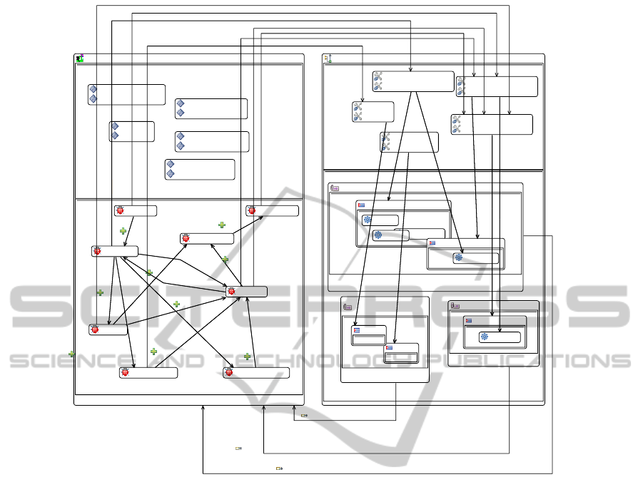
The abstract syntax of the Diagraph language is a
straightforward metamodel which conforms to a spe-
cialized graph. The Figure 1 shows a simplified ver-
sion of the positional part of the Diagraph metamodel
AFrameworkforConcurrentDesignofMetamodelsandDiagrams-TowardsanAgileMethodfortheSynthesisof
DomainSpecificGraphicalModelingLanguages
301
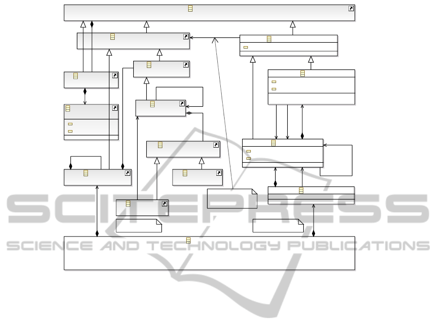
DEdge
compartment : EBoolean
compartmentName : EString
DGraphElement
name : EString
DNode
pointOfView : EBoolean
pointOfViewName : EString
DGraph
EModelElement
(from ecore)
EClass
(from ecore)
EAttribute
(from ecore)
EReference
(from ecore)
EClassifier
(from ecore)
EPackage
(from ecore)
ENamedElement
(from ecore)
EStructuralFeature
(from ecore)
DDSMLGrammar
EAnnotation
(from ecore)
EStringToString...
(from ecore)
key : EString
value : EString
Concrete Syntax
Mapping
Ecore excerpt
Diagraph excerpt
edges
1..*
target
1
source
1
nodes
0..*
eSuperTypes
0..*
eReferenceType
1
eClassifiers
0..*
eSubpackages
0..*
eStructuralFeatures
0..*
rootPointOfView
1
parentPointOfView
0..1
eAnnotations
0..*
details
0..*
abstractSyntax
1
concreteGraphicalSyntax
0..1
csMappingEdge
0..1
Figure 1: The positional part of Diagraph, related to Ecore (simplified excerpts).
(at the right) associated to the Ecore metamodel (at
the left). The stylistic part is based on another inde-
pendent metamodel that is here out of the scope, for
the sake of clarity. The metamodel of Diagraph rep-
resents an abstract diagram which has a graph struc-
ture. Nodes can be graphically integrated into each
other (if the attribute compartment is true). Elements
of the concrete syntax (DGraphElement) belonging
to the diagram are mapped by the csMappingEdge
reference to elements belonging to the Ecore meta-
model (ENamedElement). That principle of map-
ping a concrete syntax onto an abstract syntax is
also described by (Brambilla et al., 2012) in their
section 7.4.1, and our metamodel is close to a pat-
tern called "generic gcs metamodel" by these authors.
The latter distinguishes Mapping-centric Graphical
Concrete Syntaxes from Annotation-centric Graphi-
cal Concrete Syntaxes. However, our approach starts
from an annotation-centric syntax, to generate an in-
stance of the Diagraph metamodel, mapped onto the
metamodel of the target domain. That Diagraph in-
stance is a graphical notation, that is to say a concrete
syntax, which is at this stage independent of a graph-
ical renderer. The renderer can be, on one hand, the
GMF Runtime, invoked by a diagram editor resulting
from a transformation taking a Diagraph instance as
an input and producing the GMF tools artefacts, or
on the other hand, the Graphviz Runtime, activated
by a DOT model resulting from a transformation tak-
ing a Diagraph instance as an input. Our proposition
is annotation-centric in the sense of (Brambilla et al.,
2012), and also wraps an internal mapping-centric ap-
proach.
The diagram itself will be generated by a DGraph
instance, while nodes (either top nodes, or child nodes
nested in other nodes) will result of DNode instances.
A DNode may be the root of a point of view, so a new
diagram is opened starting from this DNode if the at-
tribute pointOfView is true. A DNode is always un-
derpinned by an EClass, in this case (csMappingEdge
relates to an EClass).
A DEdge object will give an edge on the diagram.
Three different kinds of edges may be created:
• The DEdge is underpinned by an EClass, thus
it carries labels taken from the EClass at-
tributes, when the csMappingEdge relates to an
ENamedElement which is an EClass.
• The DEdge is underpinned by an EReference,
when the csMappingEdge relates to an
ENamedElement which is an EReference.
This leads to two cases:
– The DEdge is a nesting edge (the compartment
attribute is true), so the target DNode is graph-
ically nested within the source DNode (and the
ICEIS2014-16thInternationalConferenceonEnterpriseInformationSystems
302
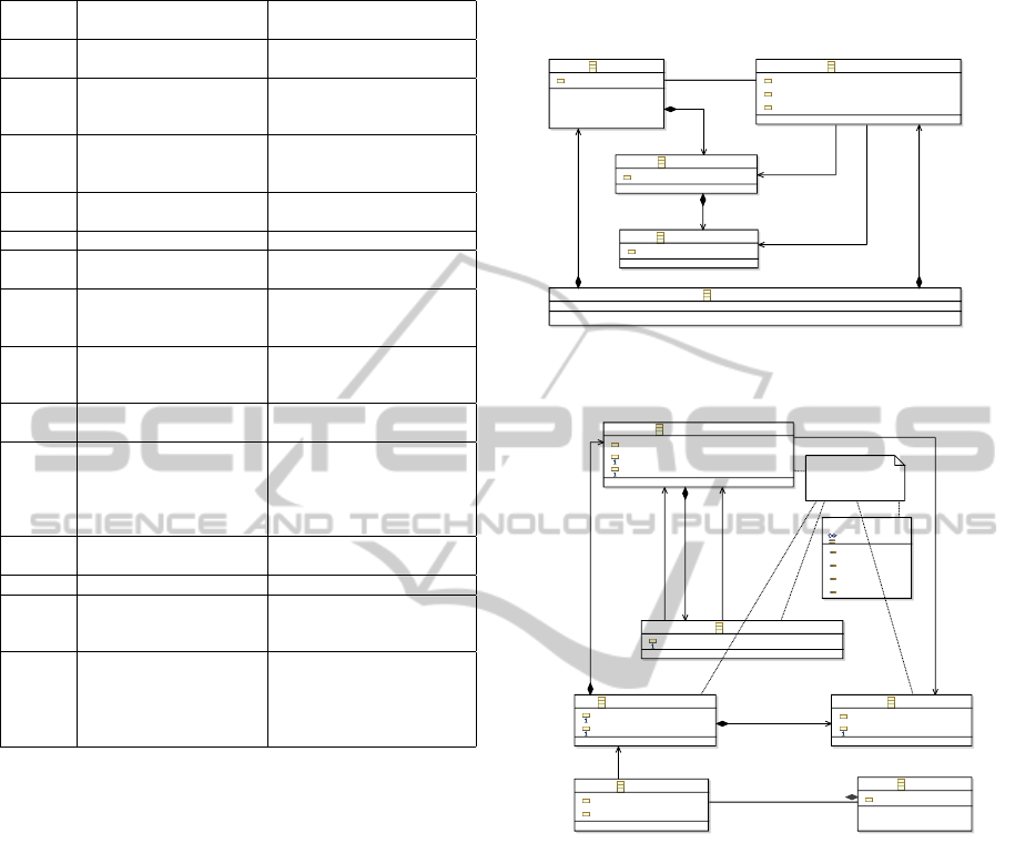
Table 2: The Diagraph vocabulary.
Keyword Semantics Abstract Syntax correspon-
dence
node A graphical shape plays
the role of the related class
DNode
link A graphical line plays the
role of the related class
(noted on the class)
DEdge
lnk Idem, but acts as a short-
cut noted on the source
class
DEdge
lsrc Defines the source for a
link
DEdge.source
ltrg Defines a target for a link DEdge.target
cont Defines a container for a
link
DNode.edges
cref A graphical nested com-
partment holds the target
node
DEdge.source (opposite of)
kref Idem, but several compart-
ments are created, one per
type
DEdge.source (opposite of)
afx A graphical affixed port is
the target node
DEdge.source (opposite of)
ref A graphical line plays the
role of the related refer-
ence (no underlying class,
thus no label can decorate
the line)
DEdge.source (opposite of)
pov A new diagram plays the
role of the node
DNode.pointOfView
view Identifies the diagram DNode.pointOfViewName
nav A graphical hyperlink
leads to a new Diagram
opened as a view
DEdge.target
label A graphical label deco-
rates the node or the link,
the label plays the role of
the related attribute refer-
enced by the argument
DGraphElement.labelAttributes
DEdge is graphically hidden).
– The DEdge is a simple relation, so the target
DNode will be shown as a sibling node on the
diagram, and a visible line generated by the
DEdge will be shown, without carrying any la-
bel (there is no EClass providing any attribute).
4.2 Stylistic Part
The stylistic part has a tree structure and can be in-
stantiated as a cascadable styles model. It is not
shown in this paper (the stylistic concern is more triv-
ial than the positional one, even if our proposition of a
cascadable mechanism similar to the principle of cas-
cading style sheets seems, as far we know, original
when applied to the field of diagramming).
5 CASE STUDY
To illustrate the paper, we propose a toy case which
is that of a publication process whose concepts are
captured in a metamodel shown in Figure 2 and 3. An
instance model is shown in Figure 5.
Researcher
name : EString
forName : EString
position : EString
Paper
name : EString
Paragraph
content : EString
ReviewNote
content : EString
PublicationStructure
researchers
0..*
paragraphs
0..*
reviews
0..*
authors
0..*
writes
0..*
reviews
0..*
papers
0..*
papers
0..*
Figure 2: Abstract Syntax of the Publication Domain (struc-
tural part).
<<enumeration>>
SequenceType
startToStart
finishToStart
startToFinish
finishToFinish
PDL Pattern
PublicationProcess
minTime : EInt
maxTime : EInt
PublicationPhase
name : EString
minTime : EInt
maxTime : EInt
Sequence
sequenceType : SequenceType
Rule
key : EString
text : EString
Paper
name : EString
Progress
percent : EInt
time : EInt
phases
0..*
linksToSuccessors
0..*
successor
1
publicationRules
0..*
rules
0..*
predecessor
1
progress
0..*
process
0..1
paper
0..1
Figure 3: Abstract Syntax of the Publication Domain (pro-
cess part).
5.1 A Language for Publications
The elements of the domain are as follows:
PublicationProcess initiated by a research team,
PublicationStructure composed by several Re-
searcher, shown Figure 2. The metamodel is
split in two parts corresponding, in the resulting
concrete syntax, to two different views, a static
(structural) view, and a dynamic (process) view. The
PublicationStructure holds many papers (Paper),
each composed of paragraphs (Paragraph), and each
paragraph of reviews (ReviewNote). One Researcher
writes many papers and one Paper has several
authors. One Researcher writes many paragraphs
and reviews them with ReviewNote. The Publication-
Process (Figure 3) is the root of the process view, that
part of the metamodel implements the PDL pattern
AFrameworkforConcurrentDesignofMetamodelsandDiagrams-TowardsanAgileMethodfortheSynthesisof
DomainSpecificGraphicalModelingLanguages
303
diagraph
(from Researcher)
node
lnk=writes
lnk=reviews
label=name
label=position
diagraph
(from Paper)
node
kref=paragraphs
diagraph
(from Paragraph)
node
kref=reviews
cont=Paper.paragraphs
label=name
diagraph
(from ReviewNote)
node
diagraph
(from Progress)
link
cont=Paper.progress
ltrg=process
diagraph
(from PublicationStru...
node
kref=researchers
kref=papers
nav:structure
Researcher
name : EString
forName : EString
position : EString
Paper
Paragraph
content : EString
ReviewNote
content : EString
Progress
percent : EInt
time : EInt
PublicationStructure
Graphic Concrete
Syntax metadata
researchers
0..*
paragraphs
0..*
reviews
0..*
progress
0..*
paper
0..1
authors
0..*
papers
0..*
papers
0..*
Figure 4: The concrete syntax annotated onto the abstract
syntax (fragment).
proposed by (Combemale et al., 2007). The two parts
of the metamodel are related by two EReferences:
neededPerson, and process. So to obtain the best
expressiveness for our graphical language, we need
to design it according to the criteria proposed by
Moody. (Moody, 2009). These criteria consider,
first, the relative position of the graphic symbols that
make up the graphical language, and then, stylistic
criteria about shapes, icons, colors and line styles.
We are interested, in this case, only on the positional
criterion. One possible notation is that shown in
Figure 5.
To specify graphical positional roles for the ele-
ments composing a metamodel, we define in Table
2 the Diagraph vocabulary, and the associated se-
mantics. The third column, Abstract Syntax corre-
spondence, refers to the Diagraph metamodel shown
Figure 1.
We use this language to annotate our metamodel
as shown in Figure 4. For example, Paper will be rep-
resented as a node, while Progress will be represented
by a link. The annotation area uses the EAnnotation
from Ecore. The EAnnotation cartridge is automati-
cally laid out exactly beneath the EClass rectangles,
figuring an extension of the class diagram (Diagraph
contributes to the layout service within the Eclipse
platform by providing its specific layout constraints).
The vocabulary of the concrete syntax definition is
directly derived from the metamodel in Figure 1 as
shown in the third column of Table 2.
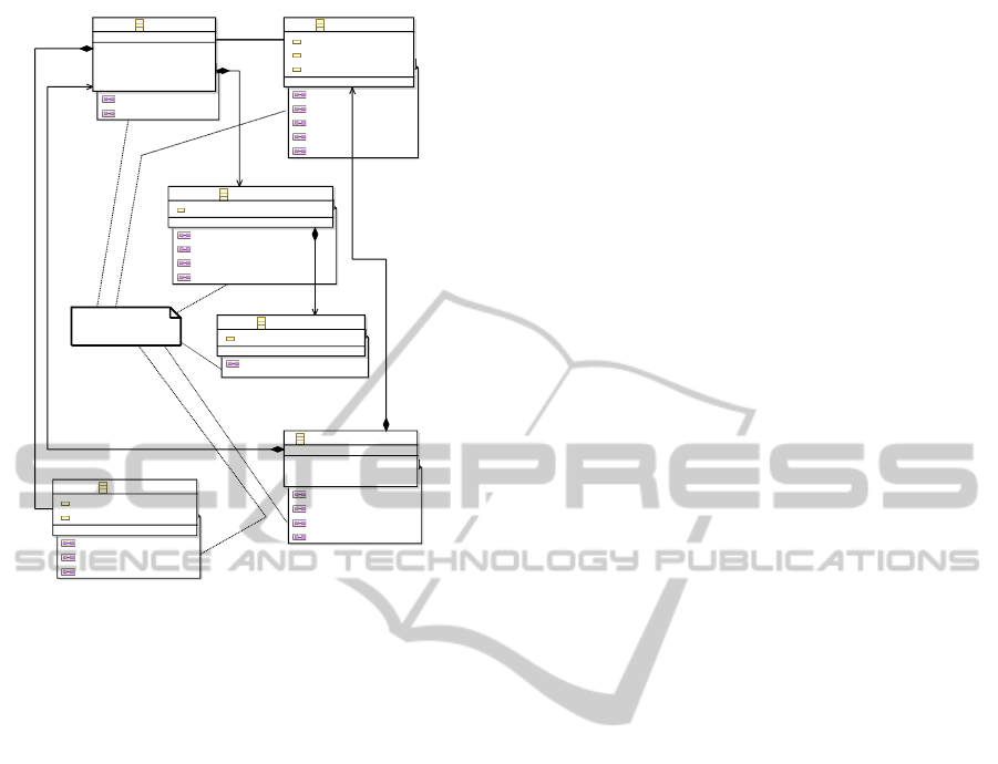
The notation, when embodied in a model instance
of the Publication metamodel augmented by the
Diagraph model named publication.diagraph, looks
like Figure 5. At this point, the style has not yet
been applied. The positional criterion is a key point
that guarantees the cognitive fit of a notation, and the
semiotic (stylistic) concern will further improve the
result. The stylistic part is not shown in this paper, for
the sake of clarity, but it follows the same principle of
an annotation based language.
6 EXPERIMENT
We evaluated the usability of Diagraph through a
Master modeling course given at the University of
Montpellier II. We asked students to implement sev-
eral simple graphical languages (see metamodels
at http://aigle-2012.googlecode.com/svn/experiment)
with each tool. We evaluated the performance of each
tool. This process was based on an agility scheme.
After an introduction to the overall implementation
of the Eclipse EMF and GMF Tooling, two work-
shops were proposed to build Graphical Domain Spe-
cific Modeling Languages based on simple metamod-
els, each consisting of 6 classes, representing a toy
modeling situation, with at least one compartmental-
ized node, several un-typed relations without any la-
bel, and also several typed links carrying labels. The
multi-view feature was not processed due to the lim-
ited time available. The metamodels are different for
each tool compared, and for each mode (supervised
and autonomous). However, they are of comparable
complexity in terms of the metamodel structure. The
profile of the subjects is a mix of research profile and
professional profile. For each experiment, each stu-
dent restitutes:
• A free report outlining the taken steps, including
text and screenshots of the experiment in progress.
• An assessment questionnaire for the process.
At the end of the experiment, an interview was con-
ducted. The students consider that the fact of being
based on a annotation language is finally more a dis-
advantage for Diagraph. They think that using anno-
tations, which are informal metadata, are not adapted
to write a formal language. The unavailability of a
wizard, a property editor, a code completion mecha-
nism also was a disadvantage for Diagraph. On the
other hand, they consider that the cognitive compre-
hension is in favor of Diagraph which is intuitive, due
to the proximity of the abstract syntax which is close
to the graphical concrete syntax, in a unique artifact.
ICEIS2014-16thInternationalConferenceonEnterpriseInformationSystems
304
process: rules + phases
manuscript
latex doublespace
style
no passive voice
template
LNCS
syntax
american english
abstract
100 words max
redaction
decision
submission
figures
state of the art
revision
publication
bibliography
Structure: researchers + papers
Lo, M
Student
Daclin, N
Assistant Professor
Derosiere, G
Student
Dray, G
Assistant Professor
Urtado, C
Assistant professor
Improving Usability in Human Computer ...
Intro
note 1
translation
note 2
Related Work
contrib 2
Some contribution
for the ...
part 1
part 2
Opinion Ext
conclusion
modif 1
FINISH_TO_START
FINISH_TO_START
START_TO_START
FINISH_TO_START
FINISH_TO_START
START_TO_START
FINISH_TO_START
FINISH_TO_START
START_TO_START
FINISH_TO_START
START_TO_START
FINISH_TO_START
FINISH_TO_START
FINISH_TO_START
START_TO_START
START_TO_START
FINISH_TO_START
FINISH_TO_START
progress = 25 %
progress = 50%
progress = 100 %
Figure 5: A Publication model created with the generated diagram editor.
Similarly, they believe that the syntax of Diagraph is
very flexible, e.g. it is easy to convert an indepen-
dent node into a nested node, by changing a keyword,
while they must undo a complex construct to do the
same operation with Obeo. Despite the difficulty of
editing Diagraph expressions by the mean of non syn-
tactically controlled annotations, they feel that the de-
sign process is faster with Diagraph.
In the case of Obeo Designer, they are close to
the concrete syntax, but far from the abstract syntax
which resides in a different instance of Eclipse. In
the participant’s mind, Diagraph is, for the moment,
an experimental tool, close to the research area, while
Obeo is adapted to industrial contexts. This fact is
coherent with the nature of the license, which is ex-
pensive in the case of Obeo while Diagraph will have
a free open-source license. We notice that Obeo pro-
cures academic free licenses; however, the users com-
plain that Obeo is a black box.
7 CONCLUSION
We have proposed Diagraph, a modeling framework
that helps the design of graphical Domain Specific
Modeling Languages – DSML, on the top of Eclipse
EMF-GMF. It includes, on the one hand a process,
and the other hand a set of annotations to enrich a sim-
ple Ecore conformant metamodel with concrete syn-
tax graphical roles, playing in one single model the
role of a grammar for graphical languages as EBNF
does for textual languages. Taking this grammar as
an input, Diagraph automatically generates all EMF-
GMF artifacts (intermediate models, diagram editors,
skeletons of unit tests). Multi-diagramming is na-
tively supported. Diagraph is non-intrusive: no de-
pendency is left in the target models; the framework
is structured in a platform independent layer based
on a clean metamodel, defining an abstraction for
graphical concrete syntax, and a transformation layer
targeting the GMF platform, but also other graph-
drawing or diagramming systems: Dot-Graphviz (yet
implemented), Graphiti, GraphML (non limitative
AFrameworkforConcurrentDesignofMetamodelsandDiagrams-TowardsanAgileMethodfortheSynthesisof
DomainSpecificGraphicalModelingLanguages
305

list, and not yet implemented). The tool includes a
"zoo" (Favre, 2006) of numerous example cases. The
Diagraph is released under an open-source license at
http://code.google.com/p/diagraph/.
Our current work is to design functional models
such as eFFBD (Pfister et al., 2012), which are hierar-
chical decompositions in the sense of IDEF0 (Ross,
1977), and also are executable models (timed Petri
nets), even if the operational semantics is not a part
of our research.
Abstract syntax and concrete syntax coevolution
is realized de facto by Diagraph. As a future work,
we would like to master the coevolution of a language
(abstract and concrete syntax) and existing instances
of that language.
We also would like to (semi) automatize the gen-
eration of a Diagraph grammar, by analyzing patterns
in the abstract syntax. Such patterns would drive the
concrete syntax: in fact they are concrete-syntax in-
tentions. We think about integrating the annotation
mechanism in the refactoring process of Eclipse, and
to improve the editor with code completion. A long-
term objective is building concrete syntaxes by ab-
stract syntax patterns recognition, but also, at a dif-
ferent (lower) meta-level, building model by imitat-
ing model patterns taken from a thematic repository.
Another objective is to improve the megamodel man-
agement by splitting the abstract syntax in several
metamodels. At last, we would like promoting the
Diagraph metamodel at the M3 level.
REFERENCES
Baetens, N. (2011). Comparing graphical DSL editors:
AToM3 , GMF, MetaEdit+. Technical report, Univer-
sity of Antwerp, Antwerp, Belgium.
Brambilla, M., Cabot, J., and Wimmer, M. (2012). Model-
Driven Software Engineering in Practice. Morgan
Claypool.
Budinsky, F., Steinberg, D., Merks, E., Ellersick, R., and
Grose, T. J. (2003). Eclipse Modeling Framework
(The Eclipse Series).
Castro Alves, A. (2011). OSGi in Depth. Manning.
Combemale, B., Garoche, P.-L., Crégut, X., and Thirioux,
X. (2007). Towards a Formal Verification of Pro-
cess Model’s Properties – SimplePDL and TOCL case
study. In 9th International Conference on Enterprise
Information Systems ICEIS, pages 80–89. INSTICC
press.
Eclipse (2001). About the Eclipse Foundation.
Falleri, J.-R., Huchard, M., Lafourcade, M., and Nebut, C.
(2008). Meta-model Matching for Automatic Model
Transformation Generation. In MODELS’08: 11th
International Conference on Model Driven Engineer-
ing Languages and Systems, volume 5301, pages 326–
340.
Favre, J.-M. (2006). Megamodelling and Etymology. In
Transformation Techniques in Software Engineering.
Schloss Dagstuhl - Leibniz-Zentrum für Informatik.
Garshol, L. M. (2003). BNF and EBNF: What are they and
how do they work?
Gronback, R. (2009). Eclipse Modeling Project: A Domain-
Specific Language (DSL) Toolkit. Addison-Wesley
Professional.
Harel, D. (1987). Statecharts: A visual formalism for com-
plex systems. Sci. Comput. Program., 8(3):231—-
274.
IEEE (2000). IEEE SA - 1471-2000 - IEEE Recommended
Practice for Architectural Description for Software-
Intensive Systems.
Juliot, E. and Benois, J. (2009). Viewpoints creation using
Obeo Designer or how to build Eclipse DSM without
being an expert developer?
Kelly, S. and Tolvanen, J.-P. (2008). Domain-Specific Mod-
eling. Wiley-IEEE Computer Society Press.
Kolovos, D., Rose, L., Abid, S., Paige, R., Polack, F., and
Botterweck, G. (2010). Taming EMF and GMF Us-
ing Model Transformation. In Petriu, D., Rouquette,
N., and Haugen, O., editors, Model Driven Engineer-
ing Languages and Systems, chapter 15, pages 211—-
225. Springer, Berlin / Heidelberg, lecture no edition.
Ledeczi, A., Maroti, M., Bakay, A., Karsai, G., Garrett, J.,
Thomason, C., Nordstrom, G., Sprinkle, J., and Vol-
gyesi, P. (2001). The generic modeling environment.
In Workshop on Intelligent Signal Processing.
Moody, D. (2009). The “Physics” of Notations: Toward
a Scientific Basis for Constructing Visual Notations
in Software Engineering. IEEE Transactions on Soft-
ware Engineering, 35(6):756–779.
Muller, G. (2009). How to create an architecture overview.
Omg (2006). Meta Object Facility (MOF) Core Specifica-
tion. Technical report.
Pfister, F., Chapurlat, V., Huchard, M., Nebut, C., and Wip-
pler, J.-L. (2012). A proposed meta-model for formal-
izing systems engineering knowledge, based on func-
tional architectural patterns. Systems Engineering.
Renaux, E., Le Pallec, X., and Moura, C. (2005). ModX -
a graphical tool for MOF metamodels. In European
Conference on Model Driven Architecture - Founda-
tions and Applications.
Ross, D. T. (1977). Structured Analysis (SA): A Language
for Communicating Ideas. IEEE Transactions on Soft-
ware Engineering, 3(1):16–34.
ICEIS2014-16thInternationalConferenceonEnterpriseInformationSystems
306
